

Page 1
TRANSPORT
®
200 ESF CSU
Configuration Guide
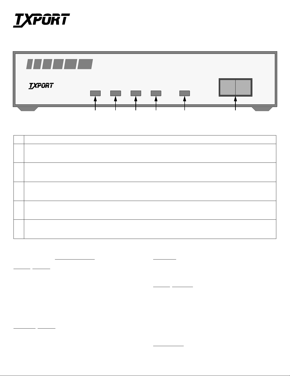
TxPORT 200 Front Panel
PRODUCTIVITY SERIES 200
Part Number 45-00041
Rev 1.00
®
TRANSPORT
PWR DTE NET LOOPFAR
LOOP NORM
CSU
654321
Front Panel Description
1 POWER: This green LED lights when power is applied to the unit.
2 DTE T1 Status: This red LED lights a minimum of 0.1 sec o nd if the internal alarm circuitry detec ts any one of the following cond itions from the
DTE: one or more BPVs, FBEs, CRCs, low ones density , or a loss of signal/loss of sync condition for Š 175 bit times from th e n etwork. The LED
stays lit until the unit detects Š 4 pulses in 32 bit times.
3 Network T1 Status: This red LED lights a minimum of 0.1 second if the internal alarm circ u itry d etec ts an y of the foll owing conditions from the
incoming T1 signal: one or more BPVs, FBEs, CRCs, or a loss of signal /loss of sync condition for Š 175 bit times from the network. T he LED
stays lit until the unit detects Š 4 pulses in 32 bit times.
4 Far end T1 status: This red LED lights a minimum of 0.1 second if the internal alarm circuitry detects a yellow alarm signal from the far end ter-
minal equipment. This condition occurs if the far end terminal is out of sync with the T1 signal from the network. The format for a yellow alarm is
bit 2 set to 0 in each DS0 (D4 mode) or 8 ones/8 zeros in the facility data link (ESF mode).
5 Loop: This amber LED lights under the following conditions: the manual loop switch is placed in the ‘LOOP’ position, the unit receives an
inband loop code for > 5 seconds, or the unit receives an FDL loop message (PLB or LL B). The LED does not light if the test switch is placed in
the ‘NORM’ position or if an inband or FDL unloop code is received for >5 seconds.
6 Test Switch : This 2-position switch is used for local testing. When placed in the local loop mode (LOOP), the unit loops the signal from the cus-
tomer equipment (DTE IN) back to the customer equip ment (DTE OUT). It also loops the recei v ed signal fro m the T1 fac ility (NET IN) back to t he
T1 facility (NET OUT). When moved back to ‘NORM’, the local loopback is removed.
SPECIFICATIONS
Network Interface
Line Rate: 1.544 Mb/s (± 50 bps)
Line Framing: D4 or ESF
Line Code: AMI or B8ZS
Line Impedance: balanced 100 Ω (± 5%)
Input Signal: DS1, +1 to -30 dB (ALBO)
Output Signal: 3.0 V, ±15%, base-peak into 100 ¾
Line Build Out: 0, -7.5, -15, and -22.5 dB attenuati on
Line Protection: 1000 V lightning, fused input/output
Jitter Control: per TR62411 and T1.403
Pulse Density: per TR62411
Equipment Interface
Line Rate: 1.544 Mb/s (± 50 bps)
Line Framing: D4 or ESF
Line Code: AMI or B8ZS
Line Impedance: balanced 100 Ω (± 5%)
Input Signal: DSX1 to 655 feet
Output Signal: Selectab le DSX 1 signal level from 0 to 655 feet
Line Protection: 1000 V lightning, input/outpu t
Mechanical
Mounting: desktop or wall
Dimensions: 1.75" H, 6.8" W, 10.5" D
Weight: 2 lbs.
Industry Standards
FCC Compliance: Part 15 Subpart B, Class A
FCC Part 68 Reg: FXKUSA- 75742-DE-N
NRTL UL 1459
CSA Certified: LR62298
DOC/CSO3: 1653 5663 A
TR 54016 September 1989
TR62411
ANSI T1.403
Environmental
Operating Temp: 0° to 50° C (32° to 122°F)
Storage Temp: -20° to 85° C (-4° to 185°F)
Humidity: 9 5% m a x (non-condensing)
Page 2
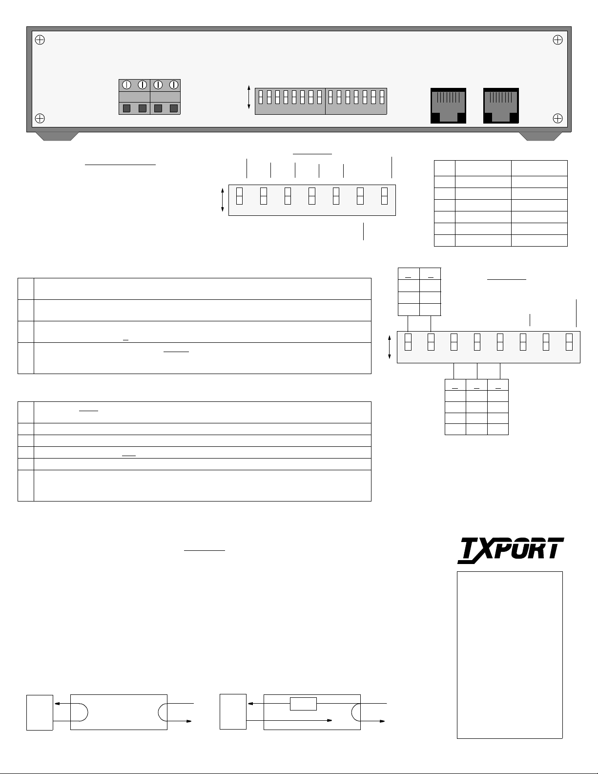
-20to-56VDC
MAX CURRENT, 100 MA
TxPORT 200 Rear Panel
PWR
(+) GND
PWR
(-) GND
A
B
S1 S2
Switch S2
Power Connectio n
200 CSU connecti ons are m ade on
the following terminals using 20-
AMI
NET
Mode
54016
A
DTE
AMI
NET
ESF
gauge stranded (or similar) wire:
GND (Ground)
PWR- (-48 VDC, ± 6 V, 45 mA)
PWR+ (Return)
B
NET
Mode
T1.403
B8ZS
DTE
B8ZS
NET
D4
Switch S1 Description
Network LBO:
1-2
the T1 facility. Refer to the diagram of Switch S1 for setting s .
DTE LBO:
3-5
ment. Refer to the diagram of Switch S1 for settings.
AIS Enable:
6
DTE during a remote loop (A
Ones Density:
8
zeros from the D TE. The ‘Disabled’ mode ignores density control and allows up to 175 ze ros to pass
towards the network before a loss of signal is declared.
These 2 positions set t he network line build ou t signal level of data tra nsmitted towards
These 3 positions set the DTE line build out transmit signal value towards the customer equip-
Options the unit to ei ther ‘generate ’ unframed all on es (an Alarm Indica tion Signal) to th e
) or to ‘pass’ the received network signal to the DTE on a remote loop (B).
Per AT& T 62 411, the ‘Enabled
’ mode allows ones density insertion after 15 successive
Switch S2 Description
ESF Mode:
1
ANSI loop/unloop commands and generates a PRM every second, but will not respond to 54016 messages.
Network Code:
2
DTE Code:
3
Network Framing:
4
DTE Framing:
5
PRM
7
sync from the DTE, an unfram ed all ones signal is gene rated to th e T1 facility. If Switch S2-1 i s set for
T1.403 operation, the unit interrupts the AIS signal with a PRM once a second.
54016 mode - unit responds onl y to 54016 CSU messages. T1.40 3 mode - unit respond s to
Sets the network line codin g, including conversion.
Sets the DTE line coding, inc lu ding conv er sion.
In the ESF
Sets the CSU to the framing of the DTE line.
: Enables /disa bles sending a perf ormance report m essage during a n AIS. If the unit de tects loss of
mode, the unit responds to T1 .403 or 54016 messages.
ESF
DTE
Spare
54321 6 7
D4
DTE
Spare
-22.5
NET
81
76543218654321 7
DTE
81
RJ48C Interfaces
PRM
Enable
Pin NET DTE
1 Data In (R1) Data Out (R)
2 Data In (T1) Data Out (T)
3/6 Not Used Not Used
4 Data Out (R) Data In (R1)
PRM
Disable
0
-7.5
-15
A
B
0 - 133 FT.
134 - 266 FT.
267 - 399 FT.
400 - 533 FT.
534 - 655 FT.
A
A
B
B B
5 Data Out (T) Data In (T1)
7/8 Chassis Gnd Chassis Gnd
A
B
A
Network
LBO
DTE LBO
A
B
A
B
A
Switch S1
54321 6 8
A
A
B
B
B
B
A
B
A
B
Loop
Loop
AIS
Network Data
7
NOTE: The ‘A’ position is the factory default for
all switch settings. If a particular user configuration requires that a switch be placed in the ‘B’
direction, then mark this sheet for future reference.
15 Zeros
Not used
Ones Density
Not used
175 Zeros
Ones Density
Loopbacks
The unit can be looped remotely by generating towards it a standard CSU line loopback code (00001
repeating for Š 5 seconds, framed or unframed). Once looped, the received signal from the T1 facility
(NET IN) is regenerated and transmitted back to the T1 facility (NET OUT). The unit is unlooped
remotely by generating towards it a standard CSU line unloop code (001 repeating for Š 5 seconds,
framed or unframed).
DIP switch S1-6 configures the unit to either generate an u nframed all o nes (AIS) sign al to t he DTE or
to pass the received da ta from the netw ork to the DTE. Th e unit respond s to the fac ility da ta link (FDL)
loop (PLB, 0000111011111111) and unloop command messages (0011100011111111).
Local Loopback
Remote Loopback
AIS
DTE
NET
DTE
NET
®
TRANSPORT
TxPORT Customer Service
127 Jetplex Circle
Madison, Alabama 35758
Customer Service Returns:
800-926-0085, ext. 227
Product Technical Support
(8 a.m. to 5 p.m.)
800-285-2755 or
205-772-3770, ext. 255
After Hours Hot Line:
205-551-7538
Page 3

TRANSPORT
®
TRANSPORT
T
O
®
200 ESF CSU
Part Number 45-00043
Rev 1.00
with TEST JACKS
Configuration Guide
TxPORT 200 Front Panel
PRODUCTIVITY SERIES
T
O
MODEL þ200 þESF / CSU
D
T
E
N
E
PWR DTE NET LOOPFAR
LOOP NORM
T
NETMONDTE
1
765432
Front Panel Description
1 Test Access Jacks: These bantam jacks provide access to the T1 line on the DTE side as follows - the left 2 ports break connection to the uni t and
make connection to the DT E, th e mid dle 2 port s are used for moni toring the signa ls pa ssing t hrough t he un it (b etween the DTE and t he netw ork),
and the right 2 ports break connection to the DTE and make connection to the unit in the direction of the network.
2 Power: This green LED lights when power is applied to the unit.
3 DTE T1 Status: This red LED lights a minimum of 0.1 sec o nd if the internal alarm circuitry detec ts any one of the following cond itions from the
DTE: one or more BPVs, FBEs, CRCs, low ones density , or a loss of signal/loss of sync condition for Š 175 bit times from th e n etwork. The LED
stays lit until the unit detects Š 4 pulses in 32 bit times.
4 Network T1 Status: This red LED lights a minimum of 0.1 second if the internal alarm circ u itry d etec ts an y of the foll owing conditions from the
incoming T1 signal: one or more BPVs, FBEs, CRCs, or a loss of signal /lo ss of sync condition for Š 175 bit times from the network. The LED
stays lit until the unit detects Š 4 pulses in 32 bit times.
5 Far end T1 status: This red LED lights a minimum of 0.1 second if the internal alarm circuitry detects a yellow alarm signal from the far end ter-
minal equipment. This condition occurs if the far end terminal is out of sync with the T1 signal from the network. The format for a yellow alarm is
bit 2 set to 0 in each DS0 (D4 mode) or 8 ones/8 zeros in the facility data link (ESF mode).
6 Loop: This amber LED lights under the following conditions: the manual loop switch is placed in the ‘LOOP’ position, the unit receives an
inband loop code for > 5 seconds, or the unit receives an FDL loop message (PLB or LL B). The LED does not light if t he test switch is placed in
the ‘NORM’ position or if an inband or FDL unloop code is received for >5 seconds.
7 Test Switch: This 2-position switch is used for local testing. When placed in the local loop mode (LOOP), the unit loops the signal from the cus-
tomer equipment (DTE IN) back to the customer equip ment (DTE OUT). It also loops the recei v ed signal fro m the T1 fac ility (NET IN) back to t he
T1 facility (NET OUT). When moved back to ‘NORM’, the local loopback is removed.
SPECIFICATIONS
Network Interface
Line Rate: 1.544 Mb/s (±50 bps)
Line Framing: D4 or ESF
Line Code: AMI or B8ZS
Line Impedance: balanced 100 Ω (±5%)
Input Signal: DS1, +1 to -30 dB (ALBO)
Output Signal: 3.0 V, ±15%, base-peak into 100 ¾
Line Build Out: 0, -7.5, -15, &-22.5 dB attenuati on
Line Protection: 1000 V lightning, fused input/output
Jitter Control: per TR62411 &T1.403
Pulse Density: per TR62411
Equipment Interface
Line Rate: 1.544 Mb/s (± 50 bps)
Line Framing: D4 or ESF
Line Code: AMI or B8ZS
Line Impedance: balanced 100 Ω (± 5%)
Input Signal: DSX1 to 655 feet
Output Signal: Selectab le DSX 1 signal level from 0 to 655 feet
Line Protection: 1000 V lightning, input/outpu t
Mechanical
Mounting: desktop or wall
Dimensions: 1.75" H, 6.8" W, 10.5" D
Weight: 2 lbs.
Industry Standards
FCC Compliance: Part 15 Subpart B, Class A
FCC Part 68 Reg: FXKUSA- 75742-DE-N
NRTL UL 1459
CSA Certified: LR62298
DOC/CSO3: 1653 5663 A
TR 54016 September 1989
TR62411
ANSI T1.403
Environmental
Operating Temp: 0° to 50°C (32° to 122°F)
Storage Temp: - 20° to 85°C (-4° to 185°F)
Humidity: 95% m a x (non-condensing)
Page 4

-20to-56VDC
MAX CURRENT, 100 MA
TxPORT 200 Rear Panel
PWR
(+) GND
PWR
(-) GND
A
B
S1 S2
Switch S2
Power Connection
200 CSU connecti ons are m ade on
the following terminals using 20-
AMI
NET
Mode
54016
A
DTE
AMI
NET
ESF
gauge stranded (or similar) wire:
GND (Ground)
PWR- (-48 VDC, ± 6 V, 45 mA)
PWR+ (Return)
B
NET
Mode
T1.403
B8ZS
DTE
B8ZS
NET
D4
Switch S1 Description
Network LBO:
1-2
the T1 facility. Refer to the diagram of Switch S1 for setting s .
DTE LBO:
3-5
ment. Refer to the diagram of Switch S1 for settings.
AIS Enable:
6
DTE during a remote loop (A
Ones Density:
8
zeros from the D TE. The ‘Disabled’ mode ignores density control and allows up to 175 ze ros to pass
towards the network before a loss of signal is declared.
These 2 positions set t he network line build ou t signal level of data tra nsmitted towards
These 3 positions set the DTE line build out transmit signal value towards the customer equip-
Options the unit to ei ther ‘generate ’ unframed all on es (an Alarm Indica tion Signal) to th e
) or to ‘pass’ the received network signal to the DTE on a remote loop (B).
Per AT& T 62 411, the ‘Enabled
’ mode allows ones density insertion after 15 successive
Switch S2 Description
ESF Mode:
1
ANSI loop/unloop commands and generates a PRM every second, but will not respond to 54016 messages.
Network Code:
2
DTE Code:
3
Network Framing:
4
DTE Framing:
5
PRM
7
sync from the DTE, an unfram ed all ones signal is gene rated to th e T1 facility. If Switch S2-1 i s set for
T1.403 operation, the unit interrupts the AIS signal with a PRM once a second.
54016 mode - unit responds onl y to 54016 CSU messages. T1.40 3 mode - unit respond s to
Sets the network line codin g, including conversion.
Sets the DTE line coding, inc lu ding conv er sion.
In the ESF
Sets the CSU to the framing of the DTE line.
: Enables /disa bles sending a perf ormance report m essage during a n AIS. If the unit de tects loss of
mode, the unit responds to T1 .403 or 54016 messages.
ESF
DTE
Spare
54321 6 7
D4
DTE
Spare
-22.5
NET
81
76543218654321 7
DTE
81
RJ48C Interfaces
PRM
Enable
Pin NET DTE
1 Data In (R1) Data Out (R)
2 Data In (T1) Data Out (T)
3/6 Not Used Not Used
4 Data Out (R) Data In (R1)
PRM
Disable
0
-7.5
-15
A
B
0 - 133 FT.
134 - 266 FT.
267 - 399 FT.
400 - 533 FT.
534 - 655 FT.
A
A
B
B B
5 Data Out (T) Data In (T1)
7/8 Chassis Gnd Chassis Gnd
A
B
A
Network
LBO
DTE LBO
A
B
A
B
A
Switch S1
54321 6 8
A
A
B
B
B
B
A
B
A
B
Loop
Loop
AIS
Network Data
7
NOTE: The ‘A’ position is the factory default for
all switch settings. If a particular user configuration requires that a switch be placed in the ‘B’
direction, then mark this sheet for future reference.
15 Zeros
Not used
Ones Density
Not used
175 Zeros
Ones Density
Loopbacks
The unit can be looped remotely by generating towards it a standard CSU line loopback code (00001
repeating for Š 5 seconds, framed or unframed). Once looped, the received signal from the T1 facility
(NET IN) is regenerated and transmitted back to the T1 facility (NET OUT). The unit is unlooped
remotely by generating towards it a standard CSU line unloop code (001 repeating for Š 5 seconds,
framed or unframed).
DIP switch S1-6 configures the unit to either generate an u nframed all o nes (AIS) sign al to t he DTE or
to pass the received da ta from the netw ork to the DTE. Th e unit respond s to the fac ility da ta link (FDL)
loop (PLB, 0000111011111111) and unloop command messages (0011100011111111).
Local Loopback
Remote Loopback
AIS
DTE
NET
DTE
NET
®
TRANSPORT
TxPORT Customer Service
127 Jetplex Circle
Madison, Alabama 35758
Customer Service Returns:
800-926-0085, ext. 227
Product Technical Support
(8 a.m. to 5 p.m.)
800-285-2755 or
205-772-3770, ext. 255
After Hours Hot Line:
205-551-7538
 Loading...