

Page 1

Introduction
1558A
APS
®
TRANSPORT
Reference Manual
34-00228
2nd Edition
Page 2

Table of Contents
General
Introduction ................................................................ 1-1
Design Highlights ....................................................... 1-1
Specifications ............................................................. 1-1
FCC Requirements....................................................... 1-2
Canadian Emissions Requirements ............................. 1-3
Warranty ..................................................................... 1-3
Ordering Numbers ...................................................... 1-4
TxPORT Customer Service ........................................ 1-4
Installation
Introduction ................................................................ 2-1
Site Preparation .......................................................... 2-1
Unpacking and Inspection .......................................... 2-1
Mounting ................................................................... 2-1
Wiring and Connections .............................................. 2-2
Chassis Ground Connection ................................. 2-2
DC Power Connection ......................................... 2 -2
Alarm Connection ................................................ 2-2
T1 Connection ..................................................... 2- 2
COM Bus Connection .......................................... 2-3
Configuration Modes ................................................... 2-3
Switch Configuration ........................................... 2-3
ROM Configuration ............................................. 2- 4
RAM Configuration ............................................. 2- 5
Manager Configuration ........................................ 2 - 5
Preservice Testing .................................................. ..... 2-5
Path A Preservice Testing .................................... 2-5
Path B Preservice Testing .................................... 2-6
Results .................................................................. 2- 7
End-to-End Pre-Service Testing .......................... 2-7
Bypass Test ................................................................. 2-8
Operation
Introduction ................................................................. 3- 1
Applications ................................................................ 3-1
General Operation ....................................................... 3-1
Revertive and Non-Revertive Switching ............. 3-1
Default Power-Up Path ........................................ 3 -1
Loss of Signal / Loss of Frame ............................ 3-1
Bipolar Violations ................................................ 3-1
CSU Loopbacks ................................................... 3- 2
Forced/Locked Capability ................................... 3-2
APS Switching Time ........................................... 3-3
APS Switching Parameters .................................. 3-3
Line Availability Timer ....................................... 3-4
Status and Performance Information .................... 3-4
Configuration Modes ........................................... 3-4
Front Panel Controls and Indicators ........................... 3-4
Supervisory Port .................................................. 3-4
Power Indicators .................................................. 3-5
Bypass Indicator .................................................. 3-5
Locked Indicator .......................... ...... ..... ............. 3-5
Status Indicators .................................................. 3-5
Manual Path Selector Switch ............................... 3-6
Path Status Alarm Indicators ............................... 3-6
Path Status LOS Indicators .................................. 3-6
Path Status Loop Indicators ................................. 3-6
Bantam Test Access Jacks ................................... 3-6
DTE Loop Indicator ............................................ 3-6
DTE Loss of Signal Indicator .............................. 3-6
Rear Panel Connections .............................................. 3-7
COM Bus Connections ........................................ 3-7
Network T1 Connections ..................................... 3-7
DTE T1 Connection ............................................ 3 - 7
Screw Terminal Connections ............................... 3-7
Option Switch Functions ............................................ 3-8
LAPS Operation
Introduction ................................................................. 4 -1
LAPS Installation ....................................................... 4 - 1
Screens and Menus ..................................................... 4-1
Common Screen Elements ................................... 4-1
Cursor Controls .................................................... 4-2
User Log On ........................................................ 4-2
Main Menu Screen ...................................................... 4-2
Circuit List Screens ..................................................... 4-3
Circuits in Alarm Screen ..................................... 4-3
Circuits in Test Screen ......................................... 4-3
Circuit List Screen ............................................... 4-3
Screen Manipulation ............................................ 4-3
Performance Screen ............................................. 4-4
Maintenance Screen .................................................... 4-6
Configuration Screen .................................................. 4-7
Utilities Screens .......................................................... 4-9
Loopback Operations .................................................. 4-10
Near CO Payload Loop ........................................ 4-10
CO Line Loop ...................................................... 4-10
CO Facility Loop ................................................. 4-11
CO Equipment Loop ............................................ 4-12
CPE Payload ....................................................... . 4-12
CPE Line ............................................ ..... ............. 4-12
CSU Loop ............................................................ 4-13
NET Loop ............................................................ 4-13
NPC Payload Loop .............................................. 4-13
BERT Testing ............................................................. 4- 14
Page 3

Copyright/Liability
Copyright
1996 TxPORT, All rights reserved. No part of this publication may be reproduced, transmitted, transcribed, stored
in a retrieval system, or translated into any language in any form by any means without the written permission of TxPORT.
Reorder # 34-00228
2nd Edition, February 1996
TxPORT shall not be liable for errors contained herein or for incidental or consequential damages in connection with
the furnishing, performance, or use of this material. TxPORT reserves the right to revise this publication from time to
time and make changes in content without obligation to notify any person of such revision changes.
Contents of this publication may be preliminary and/or may be changed at any time without notice and shall not be
regarded as a warranty.
Documentation Disclaimer
TxPOR T mak es no representation or w arranties of an y kind whatsoe v er with respect to the contents her eof and specifically disclaims any implied warranties of merchantability or fitness for any particular purpose.
Acknowledgment
The software used in the SNMP function of this product contains material derived from the following source:
Copyright 1989 by the Regents of the University of California. All rights reserved.
Redistributions in binary form must reproduce the above copyright not ice, this list of conditions, and the fol lowing
disclaimer in the documentation and/or other materials provided with the distribution. All advertising materials
mentioning features or use of this software must display the following acknowledgment:
This product includes software developed by the University of California, Berkeley and its contributors.
Neither the name of the University nor the names of its contributors may be used to endorse or promote products
derived from this software without specific prior written permission.
This software is provided by the regents and contributors ‘as is’ and any express or implied warranties, including, but
not limited to, the implied warranties of merchantability and fitness for a particular purpose are disclaimed. In no
event shall th e re gents or contribut ors be liable for any dir ect, indir ect, incidental, s pecial, exempla ry , or consequential
damages (including, but not limited to, procurement of substitute goods or services; loss of use, data, or profits; or
business interruption) however caused a nd on any theor y of liability, whether in contract, strict liability, or tort (including negligence or otherwise) arising in any way out of the use of this software, ev en if advised of the possibility of
such damage.
Page 4

General
1.0 Introduction
The TxPORT 1558A APS (Automatic Protection Switch)
unit provides automatic T1 service restoration from a
degraded or failed T1 facility to a stand by T1 facility. See
the ‘Operation’ chapter for a typical APS application.
Switching from the failed line (Path A or Path B) to the
standby (Path A or Path B) is based upon user definable
switching alarm thresholds (errored seconds, consecutively
severely errored seconds, loss of signal, loss of frame). The
1558A APS is fully compatible with all industry standard
APS equipment that complies with PUB 54017, 1991.
• Redundant Power Configurations (AC or DC)
• Bantam Test Access Jacks
• Complies with AT&T 54017 Automatic Protection
Switching, 1991
• FCC, DOC, UL, and CSA Compliant
1.2 Specifications
T1 Network Interface
Line Rate: 1.544 Mbps
Framing: ESF
Line Code: AMI or B8ZS
1.1 Design Highlights
The APS unit is designed so that it can be configured to support a wide variety of user applications. The key features
and functions are:
• Mission-Critical Automatic Protection Switching from a
Fail or Impaired T1 Facility to a Standby T1 Facility
• D4 or ESF Framing,
• AMI or B8ZS Line Coding
• Integral ESF CSUs (TR 54016 compliant)
• 24 Hour Performance History
• Revertive and Non-revertive Operation
• User -Definable Alarm Switching Thresholds
• Proactive Call-on-Alarm Reporting (requires manager)
• Desk Top or Rack Mount
1558A Automatic Protection Switch for customer premise
DS1 Interface: +1 to -27 dB ALBO, 100 Ω (± 5%)
Connector: RJ48 jack
Overvoltage Primary and Secondary lightning
Protection: fusing for line cross
ESF Mode: Pass/Block Facility Data Link
to/from Network
CPE (Equipment Interface)
Line Rate: 1.544 Mbps
Framing: D4 or ESF
Line Code: AMI or B8ZS
DSX Interface: DSX -1 to -6 dB (ALBO), RJ48
jack, 100 Ω (± 5%), 0 to 655 ft.
Connector: RJ48 jack
SUPV PWR
A
B
STATUS
ABYPASS LOCKED B
SELECT
A
PATH
AUTO
PATH
STATUS
B
ALM LOS LP
A
B
N
E
T
A
RX BRDG
TX BRDG
N
E
T
B
RX BRDG
TX BRDG
DTE
LP
LOS
RX BRDG
TX BRDG
General 1-11558A APS
TxPORT
D
T
1558A
E
Page 5

ESF Mode: Pass/Block Facility Data Link
!
to/from DTE
TR 62411: T1 interface and CSU specifications
PUB 54016: ESF requirements
Diagnostics
Line Loop: Signal regeneration only (bidirectional)
Payload Loop: Signal regenerated with new frame
synchronization, CRC6, and data.
Loop Activation Industry standard formats
and De-activation: (54016, 62411, T1-403)
Jack Access
Network Side: Bantam jacks Tx, Rx, & Bridging
for Transmit and Receive paths
DTE Side: Bantam jacks Tx, Rx, & Bridging
for Transmit and Receive paths
Alarms
Contacts: Normally Opened (NO) and
Normally Closed (NC)
Rating: 0.6A @ 125 VAC
2.0A @ 30 VDC
UL 1549, Part 2: Electrical
Industry Listings
FCC Registration: FXK USA-22709-XB-N
UL/CSA File Number: LR 62298
1.3 FCC Requirements
This equipment has been tested and found to comply with
the limits for a Class A digital device, pursuant to Part 15 of
FCC Rules. These limits are designed to provide reasonable
protection against harmful interference when the equipment
is operated in a commercial environment. This equipment
generates, uses, and can radiate radio frequency energy and
if not installed and used in accordance with the instruction
manual, may cause harmful interference to radio communications. Operation of this equipment in a residential area is
likely to cause harmful interference in which case the user is
required to correct the interference at his own expense.
Power
Unit: Dual Inputs (Power A and Power B bus)
Range: -20 to -56 VDC, ≤150 mA, 10 W,
35 BTUs
Mechanical
Mounting: Desk, wall, or rack installation (comes
with 19” rack mount hardware)
Dimensions: 17.25" W, 1.75" H, 12" D
Weight: 5 lbs.
Environmental
Operating Temp: 0° to 50° C(32° to 122°F)
Storage Temp: -20° to 85° C(-4° to 185°F)
Humidity: 95% maximum (non- condensing)
Compatibility
Shielded cables must be used to ensure compliance with the
Class A FCC li mits.
WARNING: Changes or modifications to this
unit not expressly approved by the party responsible for
compliance could void the user’s authority to operate the
equipment.
This device complies with Part 15 of the FCC rules. Operation is subject to the following two conditi ons:
1) This device may not cause harmful interference.
2) This device must accept any interference received,
including interference that may cause undesired operation.
Notice to Users of 1.544 Mb/s Service: The following
instructions are provided to ensure compliance with FCC
Rules, Part 68:
1) All direct connections to T1 lines must be made using
standard plugs and jacks.
PUB 54017: Automatic Protection Switching
Equipment, 1991
2) The following information may be required by the local
telephone company when applying for leased line facilities:
1558A APS1-2 General
Page 6

Port ID REN / SOC FIC USOC
P/N/12 - 00635 6.0 N 04DU9-BN
04DU9-DN
04DU9-IKN
04DU9-ISN
RJ48C
1.5 Warra nty
TxPORT warrants each unit against defects in material and
workmanship for a period of five years from the date the
unit was shipped to the customer. If the unit malfunctions at
any time during the warranty period, TxPORT will repair, or
at TxPORT’s option, replace the unit free of charge.
3) If the unit appears to be malfunctioning, it should be
disconnected from the telephone lines until you learn
whether the source of trouble is your equipment or the telephone line. If your equipment needs repair, it should not be
reconnected until it is repaired.
4) The unit has been designed to prevent harm to the T1
network. If the telephone company finds that the equipment
is exceeding tolerable parameters, they can temporarily disconnect service. In this case, the telephone company will
give you advance notice, if possible.
5) Under FCC rules, no customer is authorized to repair
this equipment. This restriction applies regardless of
whether the equipment is in or out of warranty.
6) If the telephone company alters their equipment in a
manner that will affect the use of this device, they must give
you advance warning so that you can have the opportunity
for uninterrupted service. You will be advised of your right
to file a complaint with the FCC.
7) The attached affidavit must be completed by the
installer.
8) In the event of equipment malfunction, all repairs
should be performed by our company or an authorized
agent. It is the responsibility of users requiring service to
report the need for service to our company or to one of our
authorized agents.
1.4 Canadian Emissions Requirements
This digital apparatus does not exceed the Class A limits for
radio noise emissions from digital apparatus set out in the
Radio Interference Regulations of the Canadian Department
of Communications.
The remedies listed herein are the users sole and exclusive
remedies. TxPORT shall not be liable for any indirect,
direct, incidental or consequential damages. The owner must
return the unit to the factory, shipping prepaid and packaged
to the best commercial standard for electronic equipment.
TxPORT will pay shipping charges for delivery on return.
The customer is responsible for mode and cost of shipment
to TxPORT. This warranty does not apply if the unit has
been damaged by accident, misuse or as a result of service
or modification by othe r than TxPORT personnel.
When returning the unit for warranty work, a Return Material Authorization (RMA) number must be obtained from
customer service at the address/ phone number given at the
end of this chapter. When calling TxPORT to obtain a
Return Material Authorization number or to arrange service,
please have the following information available:
• Model number(s) and serial number(s) for the unit(s).
• Reason for return and symptoms of problem.
• Warranty status (if known).
• Purchase order number to cover charges for out-of-war-
ranty items.
• Name and phone number of person we can contact if we
have questions about the unit(s).
• Mode of shipment required (second day air is the normal
mode of shipment for all returned material unless otherwise specified).
As soon as TxPORT has the above information, the RMA
that must accompany the item(s) returned can be issued.
NOTE: End users should use existing 48 VDC battery
sources or a CSA certified power supply.
Le present appareil numerique n’emet pas de bruits
radioelectriques depassant les limites applicables aux
appareils numeriques (de la class A) prescrites dans le
Reglement sur le brouillage radioelectrique edicte par le
ministere des Communication s du Canada .
General 1-31558A APS
Page 7

1.6 Ordering Numbers
1.7 TxPORT Customer Service
The 1558A is shipped from the factory with the following
standard items:
• The 1558A unit (the part number is F-1558-001A-1111)
• The 1558A reference manual
• 19" rack mount hardware
• Local Access PC software
• One PC to 1558A data interface cable
• AC to DC wall power transformer
• Three 10' RJ48 modular T1 cables
The following is a list of the standard and optional equip-
ment which may also be needed.
Part Number Equipment
F-1558-001A-1111 1558A unit with Dual Integral ESF CSU’s,
-20 to -56 VDC operation or
110 VAC operation.
6-3030-035-1 19" Rack Mount Hardware for 1558A.
Standard with 15 58A unit.
6-3030-036-1 23" Rack Mount Hardware for 1558A.
Ordered as an option to the 1558A.
9-1558A-003-1 PC DOS Local Access software on 3.5”
Disk. Allows the user to access unit performance, status, and configuration in formation and to perform local loop testing.
9-1001-029-2 PC to 1558A data cable, 10 ' DB9 to 6-pin
modular. Standard with 1558A unit.
30-00087 110 VAC to -48 VDC ( 200 mA max.) wall
transformer uni t, 10' po wer c able. Stand ard
with 1558A unit.
9-1001-004- 010 RJ48 8-pin modular 10' cable. Three
cables come standard with the 1558A unit.
Contact the factory for additiona l cable
lengths and types.
F-1559-000-XXXX 1559 APSM Manager. Used for central site
management of one or more co-located
1558A units. Can be ordered as AC or DC
power, one or two inte rna l mo de m s , 19’ or
23’ rack hardware. Contact the factory for
additional information.
Address: TxPORT
127 Jetplex Circle
Madison, Alabama 35758
Telephone: 800-926-0085 or
205-772-3770
Sales /Administration FAX: 205 -772-3388
Manufacturing FAX: 205 -772 - 8280
Customer Service Returns: 800-926-0085, ext. 227
Product Technical Support
Normal Hours - 8 a.m. to 5 p.m. Central, Monday – Friday
Telephone: 800-285-2755 or
205-772-3770
Emergency - Nights / Weekends / Holidays:
Telephone: 800-285-2755
E-Mail (Internet address): support@txport.com
1558A APS1-4 General
Page 8

Installation
2.0 General
Proper installation of the 1558A unit involves the following
key steps:
• Site Survey and Preparation
• Unpacking and Inspecting Equipment
• Equipment M ounting
• T1, Alarm, and Power Connections
• Setting Equipment Options
• Preservice Testing
The following paragraphs contain information and instruc-
tions to assist the user in preparing the 1558A for operation.
It is recommended that the user sequen tially follow the site
preparation and unit installation steps described.
2.1 Site Preparations
The following site preparations should be performed before
starting installation of the 1558A APS unit. First, determine
the location of 1558A unit and perform the following:
A) Determine the distance from the APS unit to the AC
outlet, or if connecting to a DC external power source, the
distance to this source. The 1558A is shipped from the factory with a 110 VAC to -48 VDC wall transformer (10 ft.
cord). If external DC is being used, insure that 26 gauge
wire is on hand to wire the external DC power source to the
1558A unit. The maximum current draw of the 1558A is
≤80 milliamps at -48 VDC.
B) Determine the distance from the T1 facility demark and
the actual location of the 1558A. After determining distance, verify that the proper cable lengths and types have
been ordered to connect from the T1 demark to the 1558A
unit. The 1558A is shipped with three RJ48 modular T1
cable, 10 feet in length.
1558A DTE DSX receive will operate is 1,400 feet (using
ABAM cable, 26 gauge, shielded wiring).
E) Verify that the T1 line is operating properly before you
attempt to install the 1558A unit. Both of the T1 lines
should be checked for error free operation for at least 1 hour
to insure that they are performing error free.
F) If the unit is going to installed in a 19’ equipment be
rack, verify that there is enough rack space available in the
rack (requires 1.75 inches per 1558A unit). Four pan head
(type 12-24 x 1/2 inch) screws are provided for mounting
the unit. An optional 23” rack mount kit is available for
applications using this size rack.
G) Verify that no external CSUs (channel service units) are
installed at the location where the 1558A is being installed.
NOTE: The 1558A unit provides intern al ESF CSU functions and cannot operate properly if another CSU is also
co-located with the 1558A.
2.2 Unpacking and Inspection
This unit is carefully packaged to prevent damage in shipment. Upon receipt, inspect the shipping container for damage. If the shipping container or cushioning material is
damaged, notify the carrier immediately and make a notation on the delivery receipt that the container was damaged
(if possible, obtain the signature and name of the person
making delivery). Retain the packaging material until the
contents of the shipment have been checked for completeness and the instrument has been checked both mechanically
and electrically.
If the contents of the shipment are incomplete or, if there is
mechanical damage or defect, notify TxPORT. If the shipping container is also damaged, or the cushioning material
shows signs of stress, notify the carrier of the damage as
well as TxPORT. Keep the shipping materials for carrier’s
inspection. TxPORT will arrange for repair or replacement
without waiting for claim settlement.
C) Normally, the provider of the T1 facility will provide
the required LBO setting (trans mit signal level) required for
connection to the T1 facilities. This value should be used
when setting the 1558A LBO transmit values (0, 7.5, 15, or
22 db) in the 1558A unit. If the value cannot be obtained
from the provider, the LBO transmit values for Path A and
Path B should be set to 0 db.
D) Determine the distance between the 1558A unit and the
terminating DTE equipment. This distance will be used
when you set the DSX transmit LBO value for the DTE T1
port on the 1558A unit. The maximum distance that the
2.3 Mounting
If the 1558A is to be installed in an equipment rack, simply
mount the 1558A in the equipment rack using the provided
mounting screws and rack mount adaptors (the 1558A can
be ordered with either 19” or 23” rack mount adaptors). If
the equipment is to be desk top installed, the user may
remove the provided rack mount adaptors and set the unit on
any flat surface. Once the equipment has been physically
located, the following rear panel wiring connections should
be performed.
Installation 2-11558A APS
Page 9

2.4 Wiring & Connections
There are several wiring connections that must be performed
to install the APS unit. The following paragraphs describe
how to attach the APS unit to the associated T1 lines, power
connections, alarm connections, and COM BUS connections. Figure 2- 1 should be used as a reference for the fol-
lowing paragraphs concerning installation of the 1558A
APS unit.
2.4.1 Chassis Ground Connection
The 1558A unit should be connected to a good earth ground.
To connect ground to the unit, attach a 26 gauge or larger
wire from the rear panel screw terminal labeled ‘GND’ to a
good earth ground.
!
Caution: Voltages in excess of 100 VDC may
be present on the T1 telecommunications lines. Before
connecting the APS unit to telecommunication lines,
insure that the rear panel screw terminal labeled ‘GND’
has been connected to a good earth ground.
2.4.2 DC Power Connections
The rear panel screw terminal labeled ‘-DC’ and ‘RTN’ are
used to connect -20 to -56 VDC to the 1558A. The 1558A
may be wired with redundant power inputs by wiring an
external source to both the PWR A and PWR B -DC/RTN
terminals. To connect power to the APS unit, perform the
following.
PWR A Wiring: Connect an external power source (-20 to
56 VDC) to the rear panel screw terminal labeled PWR A
‘DC’ and ‘RTN’. If using the provided AC to DC wall
power transformer, connect the RED
minal, the BLACK
GREEN
wire to the ‘GND’ terminal.
wire to the ‘-DC’ terminal and the
PWR B Wiring: Connect an external power source (-20 to
56 VDC) to the rear panel s crew terminal labeled PWR B
wire to the ‘RTN’ ter-
‘DC’ and ‘RTN’. If using the provided AC to DC wall
power transformer, connect the RED
minal, the BLACK
GREEN
wire to the ‘GND’ terminal.
wire to the ‘-DC’ terminal and the
wire to the ‘RTN’ ter-
2.4.3 Alarm Connections
The 1558A has alarm contacts provided at the rear panel
screw terminals labeled ‘COMMON’, ‘NC’, and ‘NO’. The
alarm relay is operated when power is present to the 1558A.
To connect the APS alarm relay to an external customer
alarm surveillance system, perform the following:
• Connect a 26gauge wire to the rear panel screw terminal
labeled ‘COMMON’ to the external alarm system.
• Connect a 26gauge wire to the rear panel screw terminal
labeled ‘ALARM NO’ (normally open) or to ‘ALARM
NC (normally closed) to the external alarm system. Note
that the alarm relay is normally operated when power is
connected to the unit.
2.4.4 T1 Connections
All T1 lines are connected to the APS unit using modular 8pin RJ48 cables (three 10' cables come with the unit). Insert
the RJ 48 connectors into the rear panel receptacles labeled
NET A, NET B, and DTE. Connect the other ends of the
cable to the appropriate T1 A and B facility equipment and
to the DTE equipment. The DTE port is not designed for
direct connection to a TELCO T1 facility. The modular pin
outs and their functions are shown in the following table.
Pin NET A & B, RJ48 DTE RJ48
1 Data In, Tip Data Out, Tip
2 Data In, Ring Data Out, Ring
3 Not Used Not Used
4 Data Out, Tip Data In, Tip
5 Data Out, Ring Data In, Ring
6 Not Used Not Used
7 Not Used Not Used
Figure 2-1 1558A Rear View
DTE COM BUSNET BNET A
S1
IN OUT
S2 S3 S4
GND
–VDC (A)
RTN (A)
–VDC (B)
RTN (B)
Alarm NO
Common
-20 to -56 VDC, 200 MA
1558A APS2-2 Installation
Alarm NC
Page 10

Pin NET A & B, RJ48 DTE RJ48
8 Not Used Not Used
2.4.5 COM Bus Connections
The rear panel COM BUS connectors (IN/OUT) are used to
communicate to/from the optional APS 1559 site m anager.
These connections are only used when a 1559 Network
manager is co-located with the 1558A(s). Bus connections
from the manager to one or more 1558A units is done in a
daisy chain fashion. That is, the COM BUS Out from the
1559 is connected to the COM BUS IN of the 1558A and
the COM BUS OUT of the 1558A is connected to the COM
BUS IN of the 1559. Physically, the connections to the
COM Bus IN/OUT are RJ11, 6-pin miniature modular
jacks. The function of the six pins associated with the jacks
are shown below.
PIN COM BUS IN COM BUS OUT
1 Not Used Not Used
2 Signal Ground Signal Ground
3 Data, output Data, Output
4 Data, input Not Used
5 Signal Ground Signal Ground
6 Not Used Not Used
2.5.1 Switch Configuration
After the equipment has been unpacked and inspected and
mounted, the next step is to configure the unit. All unit
options are set by the switch positions on four 8- position
DIP switches (S1, S2, S3 and S4) on the rear of the 1558A
unit. The 1558A is shipped from the factory with all option
switches in the OFF (factory defaul t) position. The following paragraphs briefly describe the 1558A option switches.
NOTE: After all of the option switches have been set to
the desired mode of operation, recycle the power to the
unit. At power up, the CPU will read and implement the
switch settings selected by the user.
Option Switch S1
This 8-position DIP switch is used to set the following unit
options:
• Block/Pass ESF data link configurations
• Regeneration or Pass CRC
• Master or Slave Card Operation
• Boot alarm parameters from ROM or RAM
• Boot general parameters from Switches, ROM, RAM, or
Manager
The following table describes the DIP switch settings co ntrolled by Switch S1.
2.5 Configuration Modes
Any time that the 1558A unit is initi alized (power removed,
then reapplied), all key configuration data is read by the
1558A CPU and implemented based upon the particular
configuration boot mode options selected by the user. There
are four possible configuration boot modes:
• Configure/Boot from Switches
• Configure/Boot from ROM (refer to Section 2.5.2).
• Configure/Boot from RAM (refer to Section 2.5.3).
• Configure/Boot from Manager. This requires the optional
1559 manager (refer to Section 2.5.4).
The following sections describe how to set up the 1558A to
boot using one of the above modes as well as other general
operating parameters.
NOTE: All factory default settings in this manual are
shown underlined.
(refer to Section 2.5.1).
Position Switch S1 Description
1OFF
2OFF= NET/DTE, Block Data Link
3OFF
4OFF
5OFF
6OFF
7,8 OFF
= DTE/NET, Block Data Link
ON= DTE/NET, Pass Data Link
ON= NET/DTE, Pass Data Link
= DTE/NET, Reg en. CRC
ON= DTE/NET, Pass CRC
= NET/DTE, Regen. CRC
ON= NET/DTE, Pass CRC
= Card Function, Slave
ON= Card Function, Master
= ARM from ROM
ON= ARM from RAM
,OFF = Boot from Switches
OFF,ON = Boot from Manager
ON,OFF = Boot from RAM
ON,ON = Boot from ROM
Option Switch S2
This 8-position DIP switch is used to set the following unit
options:
• Alarm on Framing Errors
Installation 2-31558A APS
Page 11

• Alarm on Loss of Signal
• AMI/B8ZS Line Coding for DTE and NET
• CSU Functions Enabled/Disabled
• Path Revert, Enabled/Disabled
• DTE Framing ESF/D4 (NET framing is fixed as ESF)
The following table describes the DIP switch settings con-
trolled by Switch S2.
Position Switch S2 Description
1OFF
2OFF
3OFF
4OFF
5OFF
6OFF
7OFF
8OFF
= Framing Errors, Enabled
ON = Framing Errors, Disabled
= LOS, Enabled
ON= LOS, Disabled
= NET/B, B8ZS
ON = NET /B, AMI
= NET/A, B8ZS
ON = NET /A, AMI
= DTE/B8ZS
ON = DTE /AMI
= CSU Mode, Enabled
ON = CSU Mode, Disabled
= Revert, Disabled
ON = Revert, Enabled
= DTE, ESF
ON = DTE, D4
Option Switch S3
This is an 8-position DIP swi tch. It is used to s et the 1558A
unit address ID for the NET A hardware and the NET B
hardware. Unique addresses must be optioned for each
1558A unit when multiple units are co-located and a 1559
Site Manager is being used. If no manager is being used, the
user should leave the DIP switches in the factory default
positions (all in the OFF or DOWN position). This configures the unit for NET A address 1 and NET B address 2.
The following table indicates how to configure the address
settings for the first six 1558A units.
NOTE: When connecting to the SUPV port using the APS
local access software, the 1558A NET A/B address es are
viewed as a single unit address and are displayed as 1.01
for addresses 1 and 2, 1.02 for addresses 3 and 4, etc.
Option Switch S4
This is an 8 -position DIP switch. The following tables indicate how to set the DIP switches for the various LBO and
DSX level settings. Note that S4-8 is not used (spare).
Positions 1 - 4 are used to set the LBO transmit level for the
NET A and NET B T1 signals. The factory default is 0 db
for the LBO settings.
LBO
0.0 DB OFF
7.5 DB OFF ON OFF ON
15.0 DB ON OFF ON OFF
22.5 DB ON ON ON ON
NET A NET B
S1 S2 S3 S4
OFF OFF OFF
Positions 5 - 7 are used to set the DSX signal level (in feet)
for the DTE port. The factory default is 0 to 133 feet for the
DTE DSX setting.
DTE DSX V alue S5 S6 S7
1 to 133 ft.* OFF O FF OFF
134 to 266 ft. OFF OFF ON
267 to 533 ft. OFF ON OFF
534 to 655 ft. ON OFF OFF
2.5.2 ROM Configuration
The 1558A may be configured to boot operational parameters from the internal ROM (read only memory). To configure the 1558A to boot from ROM, set S1 -7 and S1 -8 to the
ON position and S1 - 6 to the OFF position. With these settings, the 1558A will always boot (at power up) the unit
configuration parameters from the internal ROM settings.
The ROM unit parameters are listed below:
*APS Mgr.
Unit Pos.
1.01 1 /2 ON OFF OFF OFF OFF
1.02 3 /4 ON ON OFF OFF O FF
1.03 5 /6 ON OFF ON OFF O FF
1.04 7 /8 ON ON ON OFF OFF
1.05 9/10 ON OFF OFF ON OFF
1.06 11/12 ON ON OFF ON OFF
NET A/B
Address
Pos1Pos2Pos3Pos4Pos
5 - 8
• Block ESF data link, both directions
• Regenerate CRC6, both directions
• Slave Operation
• B8ZS line coding, both directions
• ESF framing, both directions
• Revert mode, disabled
• Availability timer set to 60 seconds
• Errored seconds set to 20
• Consecutively errored seconds set to 2
1558A APS2-4 Installation
Page 12

• Loss of frame set to Enabled
• Loss of signal set to Enab led
illustrates the testing describe d in the following preservice
steps. Testing will verify:
In addition to setting the ROM configuration options, the
user must also manually configure the following options:
• LBO transmit level setting for both NET A and NET B
• DSX transmit level/distance setting for the DTE T1 port
• 1558A unit address ( if optional 1559 manager is install ed)
2.5.3 RAM Configuration
The 1558A can be optioned to boot all alarm and operating
parameters from the battery backed RAM at power up. To
configure the 1558A for this mode of operation simply set
S1 - 7 to ON, and S1-8 to OFF. Note that the following unit
options must still be manually configured by the user:
• LBO transmit level setting for both NET A and NET B
• DSX transmit level/distance setting for the DTE T1 port
• 1558A unit address ( if optional 1559 manager is install ed)
2.5.4 Manager Configuration
The 1558A may be configured and controlled using the
optional 1559 APS M site m anag er. The manager, co-located
with one or more 1558A units (up to 56), provides both
local and remote access and control/ alarm reporting to one
or more remote locations. When the 1558A has been configured to ‘Boot from Manager’, the 1559 can access and
change all options except the following:
• 1558A Address
• 1558A LBO and DSX Levels
• Boot Mode (Switches, RAM, ROM, Manager)
To configure the 1558A to ‘Boot from Manager’, set S1- 7
to OFF and S1-8 to ON. For additional information concerning the use and operation of the 1559 manager, refer to
the TxPORT 1559 APSM reference manual.
• Path Integrity for Path A and Path B (local)
• Path Integrity for Path A and Path B (end-to-end)
The following T1 test equipment and miscellaneous cables
will be required to perform the preservice tests:
• Two T1 test sets (one required at each APS location)
• Two cables to go from t he T1 test sets to the unit RJ 48
DTE connectors at both ends.
Before proceeding, the user should read and understand the
background information presented in the following paragraphs concerning the basic operation theory of an APS service (also refer to Figure 3-1 on page 3-2).
APS service is different from “normal” point- to- point T1
service. The 1558A APS unit accepts a single source signal
from the attached DTE equipment, verifies signal density,
duplicates the signal, and then transmits it on two T1 lines
(Path A, Transmit and Path B, Transmit). This duplication
and dual transmission is also done at the far end APS equipment (if applicable).
In addition to the u nique transmitti ng functi on p erform ed by
the APS, the unit also performs a unique receiving function.
There are two identical signals being received from two T1
lines by the APS equipment (Path A, Receive and Path B,
Receive). The 1558A constantly monitors both of these lines
for satisfactory signal performance. In the event that the
present active receive line exceeds an alarm value, the APS
will automatically switch the service from the failed receive
path to the standby receive path. The active receive signal is
the path connected to the DTE equipment.
Once a path has declared an alarm condition from Errored
Seconds, Consecutively Severely Errored Seconds, Loss of
Frame, or Loss Of Signal, it will not be available for service
until a 2- minute interval has been detected that was completely error free. At that time, the path alarm circuitry will
be reset and then the path will be ready to accept service.
Unit configuration of the 1558A APS is now complete. The
final steps to complete installation is to perform the 1558 A
pre service testing steps describe in the following sections.
2.6 Preservice Testing
The preservice test checks the operational integrity of the
1558A unit. The local pre-service testing is made independently of any DTE or T1 connections. The end-to-end testing requires that the T1 facilities be connected to the unit
and that the user has a T1 test set. Figure 2- 2 on page 2 -6
2.6.1 Path A Preservice Testing
Perform the following test steps to verify that the 1558A can
run error free data from the DTE port to the NET A port and
back (local loop test). The test setup for performing this test
is depicted in Figure 2-2 on page 2-6.
1) Connect a T1 test set to the DTE RJ 48 jack at the rear
of the 1558A unit. The test set should be configured to generate a T1 signal that matches the options previously set in
the 1558A unit (D4 or ESF, AMI or B8ZS) and configured
to supply clock to the 1558A.
Installation 2-51558A APS
Page 13

NOTE: If the 1558A DTE is configured for AMI operation, the test sets must be set up to generate either a 511,
2047, or 1:7 pattern. If the 1558A is configured for B8ZS
on the DTE and NET sides, any pattern may be used (511,
2047, 1:7, QRSS, 3:24, etc.). When sending a 1:7 pattern,
though, some T1 test sets inherently cause generation of a
yellow alarm condition.
2) Verify that there is no connection at the NET A jack.
3) Manually operate the front panel Path Select Switch to
the (A) position. This forces and locks the unit to Path A.
The following unit status LEDs associated with Path A testing should be illuminated on th e unit:
• Power A or B LED ON (green)
• Status ‘Locked’ LED ON (yellow)
• Status Path Active ‘A’ ON (green)
• The Path Status, Alarm A (red) LED may be ON or OFF
depending on the alarm timer setting (0 to 900 seconds)
configured in the 1558A.
4) The 1558A unit is now looped back to the DTE port
and the T1 test set should be running in sync and error free.
If not, verify that the T1 test set framing and line coding setting match the settings configured in the 15 58A.
The 1558A unit is now looped back to the DTE port and the
T1 test set should be indicating that it is detecting pattern
sync and running error free. If “yes” proceed to Path B,
Preservice Testing. If “no”, verify that Steps 1 - 4 have been
completed properly. If there is still a problem, perform the
following:
• Loop the T1 test set to itself and verify that test set runs
error free.
• Verify that the T1 test set is properly configured to operate
with the options set in the 1558A (D4 or ESF, AMI or
B8ZS).
• Also verify that the T1 test set is configured to supply
clock (internal).
T1 Test Set Configured for:
Framing - D4 or ESF
Line Code - AMI or B8ZS
Clocking - I nternal
Pattern - QRSS, 1:8, 3:24, etc.
Figure 2-2 Local 1558A Test Diagram, Path A and Path B
Bantam Patch Cord
Path NET A
RX BRDG
N
E
T
A
TX BRDG
DTE COM BUSNET BNET A
S1
IN OUT
S2 S3 S4
N
E
T
B
RX BRDG
TX BRDG
RX BRDG
D
T
E
TX BRDG
Bantam Patch Cord
Path NET B
N
E
T
A
RX BRDG
TX BRDG
N
E
T
B
RX BRDG
TX BRDG
RX BRDG
TX BRDG
D
T
E
1558A APS2-6 Installation
Page 14

2.6.2 Path B Prese rvice Testing
2.6.3 Results
Perform the following test steps to verify that the 1558A can
run error free data from the DTE port to the NET B Port and
back (local loop test). The test setup for performing th is test
is depicted in Figure 2-2.
1) Connect a T1 test set to the DTE RJ 48 jack at the rear
of the 1558A unit. The test set should be configured to generate a T1 signal that matches the options previously set in
the 1558A unit (D4 or ESF, AMI or B8ZS) and configured
to supply clock to the 1558A (internal).
NOTE: If the 1558A DTE is configured for AMI operation, the test sets must be set up to generate either a 511,
2047, or 1:7 pattern. If the 1558A is configured for B8ZS
on the DTE and NET sides, any pattern may be used (511,
2047, 1:7, QRSS, 3:24, etc.). When sending a 1:7 pattern,
though, some T1 test sets inherently cause generation of a
yellow alarm condition.
2) Verify that there is no connection at the NET B jack.
3) Manually operate the front panel Path Select Switch to
the (B) position. This forces and locks the unit to Path B.
The following status LEDs associated with Path A testing
should be illuminated on the uni t:
• Power A or B LED ON (green)
• Status ‘Locked’ LED ON (yellow)
• Status Path Active ‘B’ ON (green)
• The Path Status, Alarm B (red) LED may be ON or OFF
depending on the alarm timer setting (0 to 900 seconds)
configured in the 1558A)
4) The 1558A unit is now looped back to the DTE port
and the T1 test set should be running in sync and error free.
If not, verify that the T1 test set framing and line coding setting match the settings configured in the 15 58A.
The 1558A unit is now looped back to the DTE port and the
T1 test set should be indicating that it is detecting pattern
sync and running error free. If so, the preservice local t esting is complete. If not, verify that Steps 1 - 3 have been
completed properly. If there is still a problem, perform the
following:
• Loop the T1 test set to itself and verify that test set runs
error free.
• Verify that the T1 test set is properly configured to operate
with the options set in the 1558A (D4 or ESF, AMI or
B8ZS).
• Also verify that the T1 test set is configured to supply
clock (internal).
The stand-alone preservice testing verifies the operational
integrity of the 1558A. If either Path A or Path B failed, but
not both, and the options have been verified, the user should
contact the factory for additional assistance (refer to the
‘General’ chapter).
2.6.4 End-to-End Pre-Service Testing
The following paragraphs describe preservice APS testing
of the 1558A when it is initially connected to the T1 facilities (Path A and Path B) and is configured with another
1558A APS at the far end.
After completing the stand-alone preservice test procedures,
the 1558A is ready to be connected to the Path A and Path B
T1 facilities for verification of end -to- end operation. These
test procedures will verify the following:
• End-to-End Error Performance of Path A
• End-to-End Error Performance of Path B
The following steps assume that there is a near end unit and
a far end unit and a technician with a T1 test set located at
both the near and the far end of the APS service.
1) Attach the Path A and Path B T1 facilities to the
respective NET A and NET B modular jacks at the rear of
the unit (both near and far locations).
2) There are four basic methods of configuring the 1558A
which directly impact the settings used in the test sets . Configure both T1 test sets per one of the following scenarios:
• 1558A DTE side configured for D4 framin g and T1 NET
sides configured for ESF.
• 1558A DTE side configured for ESF framing, and NET
sides configured for ESF.
• 1558A DTE side configured for AMI line coding and NET
sides configured for B8ZS line coding.
• 1558A DTE side configured for B8ZS line coding and
NET sides configured for B8ZS line coding.
NOTE: If the 1558A DTE is configured for AMI operation, the test sets must be set to generate either a 511,
2047, or 1:7 pattern. If the 1558A is configured for B8ZS
operation, any pattern may be used (511, 2047, 1:7,
QRSS, 3:24, etc.). When sending a 1:7 pattern, though,
some T1 test sets inherently cause generation of a yellow
alarm condition.
Make sure that one of the test sets is set for internal and that
the other is set for recovered clock.
3) Once the test sets have been configured similar to the
1558A units, connect the near and the far test set to the
DTE RJ48 jack located at the rear of the 1558A units.
Installation 2-71558A APS
Page 15

4) Operate the Service Select switch on the 1558A to the
Path A position at both the near and far 1558A units. This
forces both units to use Path A as the receive signal source.
Once this is done, both test sets shou ld indicate patt ern sync
at both the near and far locations. Run test for 15 minutes.
Test should be error free
repeat test for another 15 minutes. If errors are still detected,
a problem exists in the T1 facility. Refer problem to appropriate channels for resolution.
5) Operate the Service Select switch on the 1558A unit to
the Path B position at both the near and far 1558A units.
This forces both units to use Path B as the receive signal
source. Run test for 15 minutes. Test should be error free
both ends. If errors are detected, repeat test for another 15
minutes. If errors are still detected, a problem exists in the
T1 facility. Refer problem to appropriate channels for resolution.
6) After completing the end-to-end testing of both Path A
and Path B, connect the DTE equipment.
This completes the end-to-end operational check for the
1558A. The unit is now ready to support automatic protection switching.
at both ends. If errors are detected,
at
2) Remove the external power from the 1558A unit. Note
that all front panel LED indicators go off. The 1558A will
automatically implement the BYPASS mode which connects
the NET A T1 facility directly to the DTE port.
3) With the power still off, verify that the DTE equipment
is operating. If so, this ap plication wi ll su ppo rt the BY PASS
mode. If the DTE is not operating, this means that the signal
levels either to the DTE or from the DTE are to low for
proper operation without signal regeneration. If this is the
case, then BYPASS mode will not be viable fo r this partic ular application.
NOTE: The bypass mode requires that the DTE port and
the DTE equipment must be set for the same framing a nd
line coding as the T1 facility (ESF and AMI or B8ZS).
2.7 Bypass Test
The 1558A supports a “bypass” mode of operation which
allows the NET A path to be physically connected directly
to the DTE port. In this mode, all active electronics are
removed. The only components in the transmission paths
while the BYPASS mode is active are line protection components and test access jacks. The BYPASS mode of operation is automatically implemented when either of the
following occurs:
• Power is removed from the unit (external power failure)
• CPU detects an internal operational fault. If this occurs,
the front panel ‘BYPASS’ LED (red) will be on to indicate
that the 1558A has detected a unit fault and that it is now
operating in the BYPASS mode.
During BYPASS, their is no signal regeneration. Typically,
the transmit and receive levels to/from the T1 demark and
the terminating DTE will perform satisfactorily. However,
there is the potential that the signal levels will be unusable
by either the DTE equipment or by the T1 facility equipment.
To verify that the BYPASS mode will work in your particular application, perform the following steps:
1) First, end-to-end testing must be complete. If so, pro-
ceed to step 2.
1558A APS2-8 Installation
Page 16

Operation
3.0 Introduction
The 1558A provides the capability to automatically switch
from a “defective” T1 service to a standby facility. This
capability minimizes any actual service outage to the customer. Typically, switching from the active to the standby
path is transparent to the user (voice “hitless” with minimal
impact on data services). The 1558A Automatic Protection
Switch (APS) equipment is compatible with AT&T TR
54017, Addendum, February, 1991. When the 1558A is configured for internal ESF CSU operation, it is fully compatible with AT&T TR 54016 ESF CSU requirements.
thresholds, service will be maintained on the currently
active access path.
The switch from the active to the standby pat h is comple tely
independent of any external equipment. Switching from an
active path to a standby path only involves the receive paths
(Path A and Path B), not the transmit paths.
3.2.1 Revertive and Non-Revertive Switching
The default configuration of the 1558A APS provides nonrevertive protection. Specifically, this means that service,
when transferred to the standby path, remains on the new
path until its performance degrades past the threshold settings. This is in contrast to the optional revertive mode
which returns service to the default path when it has
returned to a minimal level of error free performance.
3.1 Applications
APS T1 protection service (per TR 54017) is either provided
by a Common Carrier (AT&T or MCI, etc.) or by the customer. When a Common Carrier provides the service, APS
equipment is installed in the central office and at the customer premise location(s). In the case of customer provided
APS, the customer installs a 1558A at both ends of the mission-critical service. Figure 3- 1 on page 3- 2 depicts some
of the more common APS applications.
TxPORT APS equipment must be installed in pairs (one
TxPORT unit at one end of the service and another unit at
the other end of the service). One unit of the pair must be
configured for ‘Master’ mode and the other as Slave mode.
3.2 General Oper ation
The 1558A constantly moni tors the status and q uality of the
path signal (A and B) received on both the active access
path and standby access path. In general, the status and quality of the signal is based on the ESF parameters described in
Section 3.1 of TR 54016 and additional parameters
described in this document and in TR 54017, 1991. If the
performance of the active path is determined to be impaired,
the protection switching equip ment will au tomatically s elect
the standby access path if that path is ready for service (not
in an alarm or a maintenance state). The level of impairment
at which a transfer is accomplished is dependent upon the
alarm threshold values set in the equipment.
Following a switch, the former standby access path becomes
the active path. The 1558A continues to monitor both of the
incoming data streams after a switch has occurred. If both
active and standby access paths exceed their specified
3.2.2 Default Power-Up Path
The desire for geographically diverse routing may also
result in diversity in the medium of transmission (copper,
fiber, microwave, etc.). Certain media have higher intrinsic
performance criteria and are therefore the service of preference. To accommodate this preference, on power up, the
1558A APS unit forces the Path A as the active path.
3.2.3 Loss of Signal / Loss of Frame
When a loss of signal is detected from the DTE side, the
1558A units generates an A IS signal towards the facility
paths (Paths A and B).
When a LOS (Loss Of Signal) is detected on the active path
from the facility side of the APS, the 1558A will immediately switch the service to the standby facility (assuming
that the standby path is not in an alarm or a maintenance
state and the LOS alarm is enabled). If the standby path is in
an alarm state, the service will remain on the failed path
until the alarm condition clears on the standby path.
Optionally, in the event that there is a signal present but it is
so impaired that it results in a LOF (Loss Of Frame), the
1558A shall immediately switch after detecting 32 consecutive framing errors (approximately 93 milliseconds) to the
standby path (assuming that it is not in an alarm or a maintenance state and the LOF alarm is enabled).
3.2.4 Bipolar Violations
The 1558A APS units will not allow BPV
(Bipolar Violations) in the DS-1 data stream unless they are
used for B8ZS (Bipolar 8 Zero Substitution) encoding for
clear channel capability. Where used, the B8ZS code will be
employed to prevent the generation of an all zero octet.
Operation 3-11558A APS
Page 17

3.2.5 CSU Loopbacks
Two ESF CSU loopbacks are provided in the 1558A unit
(CSU Line Loop and CSU Payload Loop). These loops can
be activated and deactivated by TR 54016 ESF messages, or
Inband per TR 62411. To insure maximum service availability, the following special conditions shall be applied to CSU
loopback actuation via the ESF data link messages:
• A CSU Line Loop or Payload can’t be activated on the
active path.
• If the CSU Line Loop or Payload Loop activate signal is
received by both paths simultaneously, no change of LB
state shall occur, regardless of their current states.
The “one-way” protection characteristic of the APS can
result in split-service operation. That is, service from the
1558A near APS to the 1558A far APS via one access path
Figure 3-1 Typical APS Applications
while the 1558A far APS to the 1558A near APS service i s
on the other access path. This is desirable to minimize service disruptions. However, normal maintenance and fault
isolation techniques can’t be carried out while service is
being delivered in the split mode. Service to and from the
APS must be forced to a common access, either manually or
via maintenance message, before the standby path LB can
be activated.
3.2.6 Forced/Locked Capability
A manual path select control is provided o n the APS which
selectively forces service to either Path A or Path B and
effectively inhibits the other path from accepting service.
The manual service select control supersedes all automatic
DTE
T1, A
1
5
5
8
T1, B
Slave Slave
1
5
5
7
Master
IXC Network
CO #1 CO #2
1
5
5
7
Master
T1, A
T1, B
IXC Local Loop APS application, both ends
T1, A
T1 ACCESS
1
5
5
7
Master
IXC Network
T1, B
1
5
5
7
Slave
T1 ACCESS
CO #2CO #1
IXC Network APS application
T1, A
T1, A
1
5
5
Telco and/or IXC Network
8
1
5
5
DTE
8
DTEDTE
1
5
5
DTEDTE
8
Master
T1, B
Customer Provided end-t o -end APS Applicat i on
T1, B
Slave
1558A APS3-2 Operation
Page 18

transfers and forces the path not inhibited to carry the service, regardless of its status or condition.
3.2.7 APS Switching Time
Two times are of significance in specification of the APS
protection switching function. Th e first is the latency period
between the point when the switching criteria is satisfied on
the active access path and the point at which restoration
occurs on the standby access path. This time is less than 50
milliseconds.
The second is the duration of the switching transient event
associated with physically moving service from the active to
the standby access path. The 1558A APS can complete the
transition from active to standby path within 1 bit time.
The decision to transfer service from the active path to the
standby path, and vice-versa, is based on a priority system,
where the highest priority condition that satisfies a transfer
controls, regardless of the conditions in lower priorities.
• Priority 1 – LB Status:
If the standby path’s LB is activated, then service shall
remain on the active path.
• Priority 2 – Failed Status:
If the standby path is in a failed state then service shall
remain on the active path. A failed state could be a result
of excess ES, CSES, LOS, or LOF.
• Priori t y 3 – Error Event Threshold Crite ria:
This level of transfer is based on the occurrence of 1 second events within the current 15 minute interval as
described in the TR 54017 Addendum.
Each error event requires storage for the following values:
threshold setting, current count, and a service transfer flag.
The threshold setting for the events (ES and CSES) may
range from 1 to 900 seconds. Transfer of service is based
only on these events.
If the threshold of an event is 0, that event is inactive and is
not a criterion for transfer of service. The current count tallies the total number of error event seconds within the current 15 minute interval. This count is reset at the beginning
of a new 15 minute interval.
The service transfer flag is set for the event that causes a
transfer of service. It allows the cause of the service transfer
to be determined even after the current count has been reset
at the beginning of a new interval. This flag is reset when a
service transfer acknowledgment message is received, which
is described in the next section.
3.2.8 APS Switching Parameters
The 1558A unit switches from the active line to the standby
line based upon user definable alarm parameters. The alarm
performance parameters that can configured by the user are
Errored Seconds, Consecutively Severely Seconds, Loss of
Signal, and Loss of Framing. These alarm parameters and
their definition are described below.
Errored Seconds (ES) - The user can define that the 1558A
switches from the active line to the standby lin e when a certain number of errored seconds have been detected during
the current 15 minute performance interval (900 seconds).
The ES threshold can be set from 0 (setting this parameter to
a zero value disables ES switching) to 900 seconds. The
1558A is configured at the factory with 20 errored seconds
as the default errored second value. The definition of an ES
is a second containing one or more CRC errors.
Consecutive Severely Errored Seconds (CSES) - The user
can define that the 1558A switches from the active line to
the standby line when a certain number of Consecutive
Severely Errored Seconds have been detected during the
current 15 minute performance interval (900 seconds). The
CSES threshold can be set from 0 (setting this parameter to
a zero value disables CSES switching) to 900 seconds. The
1558A is configured at the factory with 2 consecutive
severely errored seconds as the default CSES value. The
definition of a CSES is when two or more consecutive SES
have been detected (note that CSES are transparent to the
boundary between 15 minute intervals). A severely errored
second is defined as a second containing 320 or more ESF
errors.
Loss of Signal (LOS) - The user can define that the 1558A
switches from the active line to the s tandby line wh en a los s
of signal state has been detected. The 1558A is shipped
from the factory with loss of signal parameter enabled. The
definition of a loss of signal is when the receive signal from
the network contains ≥175 consecutive bit intervals containing all zeros (no pulses). The condition will be cleared when
one or more intervals contain a one.
Loss of Frame (LOF) - The user can define that the 1558A
switches from the active line to the s tandby line wh en a los s
of frame error state has been detected. The 1558A is shipped
from the factory with the loss of frame parameter enabled.
An LOF alarm condition occurs when 32 or more consecutive ESF frames contain frame bit errors.
When the current count of either ES or CSES is greater than
or equal to the threshold setting or when a LOS or LOF (if
enabled) is detected, the service shall be transferred from
the active path to the standby path as long as the standby
path is available (not in an alarm state or in a looped state).
A requirement f or th e sta ndby p ath to b e available is that the
timer circuitry, described below, is not active and a LOS or
LOF condition does not exist.
Operation 3-31558A APS
Page 19

3.2.9 Line Availability Timer
The line availability timer is used to quantify when a path is
eligible to accept service.Line availability is determined by
the APS by observing a defined wi ndow of tim e in wh ich no
active error events have occurred. The APS line availability
timer can be set to any value from 0-900 seconds. This
value represents the minimum amount of time, free of active
error events, that must expire before this path is declared as
ready to accept service. The factory default setting for the
line availability timer is 60 seconds.
The line availability timer requires storage for the timer setting and the active timer count. If the timer setting is 0, the
timer circuitry is disabled and the path is always available
for service, assuming that there are no active alarm conditions present. If the timer setting is set to a value ranging
from 1 to 900 seconds and a service transfer takes place, the
standby unit initializes the active timer count to the timer
setting. When the timer expires, thi s standby path becomes
available for a service transfer. This timed period must be
free of errors for all active events. If an error occurs, the
active timer count is reset.
When operated in the optional revertive mode, the path
availability timer serves to force restoration of service back
to the default access, Path A. That is, when service is
switched from Path A, it will remain on the standby path
(Path B) only until Path A’s availability timer expires. The
factory default is Revert set to OFF.
3.2.10 Status and Performance Information
The current status and performance parameters are stored in
the internal registers of the 1558A. Access to this information is via the 1559 APSM site manager (optional) or the
LAPS (local access protection switch) PC software. The
LAPS software is shipped with each 1558A unit.
The following information can be viewed by the user using
either the 1559 APS Site Manager or the provided APS
Local Access DOS Software.
• This path is currently carrying the service.
• This path is currently in a failed state.
• This path is currently in an inhibit state.
• The LB of this path is currently activated.
• The other path is currently in a failed state.
• The other path is currently in an inhibit state.
• The LB of the other path is activated.
• The manual locked control state.
• Current status
• Current interval Occurrences
• Current interval Duration
• Current Interval Timer
• Occurrences - Intervals, 1 through 96
• Duration - Intervals, 1 throug h 96
• Valid Intervals Total
• Occurrences, 24-hour value
• Duration, 24-hour total
• 30-day switch occurrence history
3.2.11 Configuration Modes
Any time that the 1558A unit is i nitialized (power removed,
then reapplied), all key configuration data is read by the
1558A CPU and implemented based upon the particular
boot mode options selected by the user (see Installation Section for additional information). The four possible BOOT
mode configurations are described below:
1) Boot from Switches - At power up, the 1558A CPU
reads the values set at the rear panel option switches and
configures the unit per those switch settings.
2) Boot from Manager - At power up the CPU sends a
message to the 1559 APS manager for a download of 1558A
unit configuration information. Note that this mod e requires
that a 1559 site manager be installed.
3) Boot from RAM - At power up, the 1558A CPU reads
the unit configuration from the battery backed RAM data.
4) Boot from ROM - At power up, the 1558A CPU reads
the factory firmware default values from ROM. The factory
default ROM configuration option settings are:
• Block data link, both directions
• Regenerate CRC6, both directions
• Slave operation
• B8ZS line coding, both directions
• ESF framing, both directions
• Revert mode, disabled
• Availability timer set to 60 seconds
• Errored seconds set to 20
• Consecutively errored seconds set to 2
• Loss of frame set to enabled
• Loss of signal set to enabled
3.3 Front Panel Controls & Indicators
The front panel of the APS unit contains several LED indicators, a SUPV access port, a path select switch, and s everal
bantam test access jacks. The following paragraphs briefly
describe the operation of these items (refer to Figure 3- 2
and the 1558A Configuration at the end of this manual).
1558A APS3-4 Operation
Page 20

3.3.1 Supervisor Port
3.3.3 Bypass Indicator
The front panel SUPV port allows the user to connect to the
1558A via a PC running the supplied APS LAPS (Local
Access protection software) application. This user interface
software allows the user to gain access to the unit configuration data, unit status, unit performance, and perform local
and remote loopback testing.
Electrically, the SUPV port is RS232 and the data format is
19.2 Kb, asynchronous. The cable used to connect the PC to
the SUPV port is a DB9 (female) to 6-pin modular cable.
This cable is provided with the 1558A unit. The pin functions for the SUPV port are shown in the following table.
Pin SUPV Port Wiring
1 Not Used
2 Ground
3 Data, Out
4 Data, In
5 Ground
6 Not Used
3.3.2 Power Indicators
The 1558A has two green power LED indicators (Power A
and Power B). One or both of the indicators will be ON
when a nominal power source of -20 to -56 VDC is present
on the rear panel PWR A and PWR B screw terminals,
respectively. The indicator(s) will be OFF if the power is not
present at the respective power screw terminals. Only one
power input is required to operate the unit. If power redundancy is crucial, both the Power A and Power B inputs
should be wired to an external -20 to -56 VDC source. The
1558A unit is shipped with a single 110 VAC to -48 VDC
wall power unit.
The red BYPASS LED indicates whether or not the 1558A
is presently in a BYPASS mode of operation. The LED will
be ON if the unit has detected a CPU watchdog operational
fault. The LED will be OFF under normal operation.
When active, the BYPASS mode connects the NET A T1
facility directly to the DTE port. In this mode, all of the
active electronics are bypassed. That is, the only elements in
the path are passive line protection circuitry components for
the NET A port and the DTE port. During BYPASS operation, the 1558A acts only as a passive device and does not
perform any signal regeneration functions.
Activation of the BYPASS mode occurs when either the
CPU watchdog timer circuitry is defective (indicates a CPU
or software problem) or when power is removed from the
unit. The BYPASS mode is terminated when either the CPU
watchdog circuitry is determined to be normal or when
power is restored to the unit.
3.3.4 Locked Indicator
The user can manually force and lock either the A or B T1
path as the active path by moving the PATH SELECT switch
from the AUTO position to either the A or B Path Select
positions. This action will force the 1558A to use the
selected path. Also, the 1558A is now manually locked to
this path and will not switch from it, even if the selected
path is in a failed state or subsequently fails. When the
1558A has been manually forced to either the A or B PATH,
the amber LOCKED LED indicator will be on. Moving the
PATH SELECT switch back to the AUTO position will turn
off the LOCKED LED and restore normal APS operation.
Caution: Placing the 1558A in a manually locked
mode prevents the u nit from perf orming automa tic protection switching.
SUPV PWR
A
B
STATUS
ABYPASS LOCKED B
Figure 3-2 1558A Front View
SELECT
A
PATH
AUTO
B
PATH
STATUS
ALM LOS LP
A
B
N
E
T
A
RX BRDG
TX BRDG
N
E
T
B
RX BRDG
TX BRDG
DTE
LP
LOS
RX BRDG
TX BRDG
Operation 3-51558A APS
TxPORT
D
T
1558A
E
Page 21

3.3.5 Status Indicators
The 1558A front panel STATUS A and B LEDs (amber)
indicate which of the two T1 receive paths (A or B) is presently being utilized to provide service to the CPE equipment.
3.3.6 Manual Path Selector Switch
The front panel manual PATH SELECT switch is used to
force the 1558A to use either the A or B path as the active
line. If the user momentarily moves the switch to either the
A or B position and then returns the s witch to the normal/
center position, the 1558A will force service to the selected
path (A or B). If the user leaves the switch in the manual A
or B position, the 1558A will LOCK the service to this path
and turn on the LOCKED LED.
3.3.7 Path Status Alarm Indicators
Path A/B Jacks Function
Transmit (TX) to T1
facility (upper left
jack)
Receive (RX) from
T1 facility (lower
left jack)
Transmit Bridge
(BRDG) to T1 facility (upper right
jack)
Receive Bridge
(BRDG) from T1
facility (lower right
jack)
Allows the user to ga in access to th e tra n smit T1 path towards the T1 fa c ilit y. Inserting a test cord into this jacks disconnects
the 1558A from the T1 facility
Allows the user to gain access to the
receive T1 path from the T1 facilit y.
Inserting a test cord into this jacks disconnects the 1558A from the T1 facility
Allows the user to bridge/monitor the
transmit T1 signal towards the T1 faci lity.
Note, test set must be set to the bridge termination mode.
Allows the user to bridge/monitor the
receive T1 sign al from the T1 facil ity . Test
set must be set to the bridge termination
mode.
The 1558A alarm circuitry is driven by the alarm parameters
defined by the user at time of installation. The user definable
alarm parameters are ES (errored seconds), CSES (consecutively errored seconds), LOS (loss of signal), LOF (consecutively ESF errored frames). When any of these alarm
thresholds are met or exceeded, the ALARM LED indicator
(red) will be on for the path (A or B) that has “failed”.
3.3.8 Path Status LOS Indicators
The 1558A LOS (loss of signal) Path A and B indicators
(amber) will be ON when no T1 pulses are being detected
on the receive signal paths from the network. The definition
of loss of signal is no pulses for 175 bit times. The loss of
signal state will be cleared when one or more data pulses are
detected on the receive path. After the pulses are detected,
the respective LOS indicator will be turned OFF.
3.3.9 Path Status Loop Indica tors
The 1558A can respond to CSU loop commands (both
inband and FDL) and local or remote APS loop commands.
When a loop has been activated (Path A, B, or DTE) the
respective front panel LP LED indicator (amber) will be
ON. If no loop is active, the LP indicator will be OFF.
3.3.10 Bantam Test Access Jacks
DTE Jacks Function
Transmit (TX) into
the 1558A from the
DTE equipment
(upper left jack)
Receive (RX) from
the 1558A to the
DTE equipment.
(lower left jack)
Transmit Bridge
(BRDG) to T1 facility (upper right
jack)
Receive Bridge
(BRDG) to DTE
equipment.(lower
right jack)
Allows the user to ga in access to th e tra n smit T1 path from the DTE into the 155 8A.
Inserting a test cord into this jacks disconnects the 1558A from the DTE equipment
Allows the user to ga in access to th e tra n smit T1 path from the 1558A to the DTE
equipment. Inserting a test cord into this
jacks disco n n ects the 1558 A fr o m t he
DTE equipment
Allows the user to bridge/monitor the
transmit T1 signal coming from the DTE
equipment.Note, test set must be set to the
bridge termination mode.
Allows the user to bridge/monitor the
receive T1 signal coming from the 1558A
to the DTE equipment.Note, test set must
be set to the bridge termination mode.
3.3.11 DTE Loop Indicator
The 1558A DTE port can be looped either locally or
remotely by receipt of soft commands generated either from
the LAPS software interface or from a far end unit. When a
loop has been activated, the front panel DTE LP indicator
(amber) will be ON. If no loop is active, the DTE LP indicator will be OFF. Note that a DTE loop interrupts service.
Bantam test access jacks and bridge/monitor jacks are provided to gain physical access to the T1 Path A (NET A), T1
Path B (NET B), and the T1 DTE path. The placement of
the jacks is depicted in Figure 4- 2 on page 4-11. The function of these ja cks is describ ed in the follo w ing table.
3.3.12 DTE LOS Indicator
The 1558A LOS (loss of signal) DTE port indicator (amber)
will be ON when no T1 pulses are being detected on the
receive path from the CPE equipment. A loss of signal con-
1558A APS3-6 Operation
Page 22
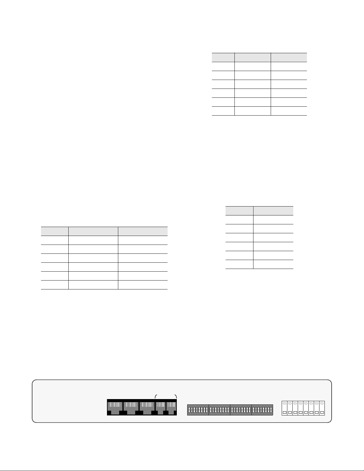
dition occurs if there are no pulses for 175 or more bit times.
The loss of signal state will be cleared when one or more
data pulses are detected on the receive path. After the pulses
are detected, the LOS LED indicator will be turned OFF.
3.4 Rear Panel Connections
All APS unit wiring connections and option switches are
located on the rear panel of the 1558A unit. The function
and description of these items are discussed in the following
paragraphs (refer to Figure 3- 3 and the 1558A Configuration Guide at the end of this manual).
3.4.1 COM Bus Connections
The two 6-pin modular connectors labeled COM BUS IN
and COM BUS OUT on the rear panel may be used to connect to the optional 1559 APSM site manager. These ports
are wired to allow daisy chaining one or more units off of
the APSM (the OUT port is connected to the IN port from
unit to unit). The COM BUS IN and OUT connectors are
physically RJ11, 6 -pin modular jacks. The function of the 6
pins are described in the tab le below. For additional information concerning the site manager, consult the TxPORT
1559 manual.
PIN COM BUS IN COM BUS OUT
1 Not Used Not Used
2 Signal Ground Signal Ground
3 Data, output Data, Output
4 Data, input Not Used
5 Signal Ground Signal Ground
6 Not Used Not Used
3.4.2 Network T1 Connections
The NET A and the NET B T1 modular jacks are used to
connect the 1558A to the T1 facilities u sing RJ48 modular
cables. Physically, the 1558A NET A and NET B connectors are RJ48, 8 - pin modular connector. The usage of each
of the eight pins found in the connector are described in the
table below. The 1558A unit comes with three ten foot RJ48
cables (NET A, NET B, and DTE).
PIN NET A NET B
1 Data In, Tip Data In, Tip
2 Data In, Ring Data In, Ring
3,6 Not Used Not Used
4 Data Out, Tip Data Out, Tip
5 Data Out, Ring Data Out, Ring
7,8 Not Used Not Used
3.4.3 DTE T1 Connection
The DTE T1 modular jack is used to connect the 1558A to
the customer premise equipment using a RJ48 modular
cable. Physically, the DTE connector is RJ48, 8 - pin modular connector. The DTE T1 port is not designed connect
directly to a TELCO T1 facility. The 1558A unit comes with
three ten foot RJ48 cables (NET A, NET B, and DTE).The
usage of each of the eight pins found in the connector are
described in the following table.
PIN DTE
1 Data In, Tip
2 Data In, Ring
3,6 Not Used
4 Data Out, Tip
5 Data Out, Ring
7,8 Not Used
3.4.4 Screw Terminal Connections
Several screw terminals are provided at the rear of the unit
for connecting external power and alarm wiring. All connections to these terminals strip should be made using 26-
gauge wire, or larger. The purpose of these terminals is
briefly described as follows:
Ground: This terminal is used to connect the chassis
ground to an external earth ground.
Figure 3-3 1558A Rear View
DTE COM BUSNET BNET A
S1
IN OUT
S2 S3 S4
GND
–VDC (A)
RTN (A)
–VDC (B)
RTN (B)
Alarm NO
Common
-20 to -56 VDC, 200 MA
Operation 3-71558A APS
Alarm NC
Page 23

Pwr A Terminals (-DC, RTN): These two terminals are
used to connect an external -20 to -56 VDC power source to
the 1558A. The positive side of the external power source
should be connected to RTN and the negative side to -DC.
Pwr B Terminals (-DC, RTN): These two terminals are
used to connect a redundant (second) external -20 to -56
VDC power source to the 1558A. The positive side of the
external power source should be connected to RTN and the
negative side to -DC.
Alarm Terminals (Com, NO, NC) : These three terminals
are used to connect the APS unit alarm relay contacts to
external alarm alert equipment. The APS unit alarm relay
contacts can be wired as Normally Open or Normally
Closed. The contacts are rated at 2 amps @ 30 VDC. When
the APS is powered, the alarm relay is in the operated state
and the NO (normally open) contacts are open and the NC
(normally closed) contacts are closed.
3.5 Option Switch Functions
Switch S2
Framing Errors: The 1558A can be optioned to alarm
based upon receipt of 32 or more consecutive framing
errors. This parameter can also be disabled.
Loss of Signal: The 1558A can be configured to alarm
based upon loss of signal for > 175 bit intervals. The parameter can also be disabled.
AMI/B8ZS: The 1558A can be configured for either AMI
line coding or B8ZS line coding.
CSU Mode: The 1558A can be configured to ignore CSU
loop and performance commands (disable) or to respond to
CSU loop and performance commands (enable).
Path Revert: The 1558A can be configured to revert back
to Path A after a failure (enable) or to remain on Path B
(disable). Revert should be enabled if the user has a preference for the Path A loop facilities.
DTE Framing: The 1558A DTE port can be configured to
operate in the D4 framing mode or in the ESF framing
mode. Note that the NET A and B paths are always operated
in the ESF mode.
The 1558A rear panel has four 8- position DIP switches for
configuration purposes. Refer to Section 2.5. 1 on page 2 - 3
and the 1558A Configuration Guide at the end of this manual for instructions on setting switches. The following paragraphs explain the operational functions of these switches.
Switch S1
Block/Pass FDL: The 1558A can be configured to either
block or pass the 4 kb ESF facilities data link (FDL) from
the NET A/B path to the DTE port and from the DTE port to
the NET A/B ports.
Regenerate/Pass CRC: The 1558A can be configured to
either regenerate or pass CRC from the network to the DTE
port and from the DTE port to the network.
Master/Slave: The 1558A can be configured as either a
master or slave unit. The key difference between a master
and slave 1558A unit is that a master 1558A unit can access
and control a remote slave 1558A but a slave unit cannot
access and control a master.unit.
ARM ROM/ RAM: The 1558A can be configured to boot
the alarm thresholds from either the ROM or from the unit’s
RAM. The ROM defaults are ES = 20, CSES = 2, LOS =
Yes, LOF = Yes, and Line Availability Timer = 60.
Switch S3
If multiple 1558A units are co-located at a site and if the site
is being managed by a 1559 APS site manager, this eight
position DIP switch is used to configure a unique address
for each of the 1558A units being managed by the 1559.
Typically, there will not be a 1559 located with the 1558A
and the factory default address (Address 1/ 2) can be used
(all switches in the OFF position). If multiple units are
located with a 1559, simply set each unit to a unique address
using Switch S3 (see the Installation chapter fo r instructions
on setting addresses).
Switch S4
Option Switch S4 is used to configure the LBO value for the
NET A and NET B ports and the DSX level for the DTE
port The NET A and NET B LBO value that can be set are
0, 7.5, 15.0, and 22.5 db. The DTE DSX values can be set
for 133 feet, 266 feet, 399 feet, 533 feet, and 655 feet.
The next section discusses the general operation and use of
the LAPS (Local Access Protection Switch) software.
Boot Modes: The 1558A unit configuration can be set at
power up by the parameters stored in the ROM, RAM,
option switches, or from the optional 1559 site manager.
1558A APS3-8 Operation
Page 24

LAPS Operation
4.0 Introduction
Access to key 1558A configuration, performance, and testing functions can be locally performed by the user by
installing the provided 1558A LAPS (Local Access Software) on a PC computer and attaching the provided PC to
1558A cable to the front panel SUPV port. The following
sections describe the features and functions of the 1558A
Local Access software and how to install the software on a
PC.
4.1 LAPS Installation
It is recommended that the user copy the LAPS software to
a directory on the PC hard drive and then store the original
disk in a safe place. The following steps will assist the user
in installing the LAPS software.
1) Power up the PC to be used and insert the LAPS soft-
ware into the A floppy drive. From the C drive DOS prompt
enter the following command:
C:\LAPS> copy A:*.*
4) The PC copies all files to the directory called LAPS.
When the prompt indicates that all files have been copied,
remove and store the original disk in a safe place.
5) After removing the disk in drive A, enter the following:
C:\LAPS> laps 1 (or laps 2)
Entering ‘LAPS 1’ or ‘LAPS 2’ directs the program to use
either COM 1 or COM 2. The computer responds by launching the LAPS application. Once the application is running,
the user log on screen will be displayed and the user is
prompted to “Press the Enter key to begin”. Once the
<return> key is pressed, the LAPS main menu is displayed.
6) Attach the provided PC / LAPS data cable from the PC
COM port to the SUPV port on th e 1558A. Installation of
LAPS and the physical connection to the 1558A is now
complete.
The user should read and understand the following LAPS
user interface information before attempting to use the
LAPS software.
C:\> md laps
The PC creates a directory on the C drive named LAPS
2) At the DOS command line, enter the following:
C:\> cd laps
The PC responds by displaying C:\LAPS
3) From this prompt enter the following DOS command:
Figure 4-1 LAPS Menu Tree
MAIN MENU
Circuits
in Alarm
Circuits
in Test
Log On Log Off
Circuit
Listing
4.2 Screens And Menus
4.2.1 Common Screen Elements
The LAPS user interface is a user friendly, menu driven system. The available menus for the LAPS interface are shown
in Figure 4 -1. Each LAPS screen has several components
that are common to all screens and will be discussed in this
section only. The following paragraphs cover each of these
components individually. Refer to the Main Menu screen
ConfigurationUtilitiesMaintenance
Performance
Switch Occurrence History
Date Time Header Auto Logoff
LAPS Operation 4-11558A APS
Page 25

(Screen 4-2 on page 4-3) which depicts these common
screen elements.
Date and Time: The top right corner of the LAPS screen
always displays the current date and time. The date and time
can be set as described in Section 4.7 on page 4 -9.
Revisions: The LAPS software revision level is shown
below the time. Refer to these numbers when contacting the
factory with hardware or software related inquiries.
Location Header: The location name is displayed in the
center of the second display line.The header can be changed
under the Utilities menu.
Menu Title: The menu title (fourth line, center) denotes the
general classification of the user interface that the user presently has accessed.
Messages: The message lines (bottom two) show alerts,
error messages, help messages and to accept typed, user
input. The use of typed input will be expanded upon in sections of this manual where it is directly applicable.
For PC computers which do not have these particular keys
or have only some of them, a set of cursor control commands are supported. Each of these commands is effected
by holding down the <Ctrl> key while pressing a command
key. The available commands are listed in the following
table. These commands may be freely mixed with the use of
the normal cursor command keys at the user’s discretion.
Keyboard Command Alternate Command
< left arrow > < Ctrl - S >
< right arrow > < Ctrl - D >
< up arrow > < Ctrl - E >
< down arrow > < Ctrl - X >
< backspace > < Ctrl - H >
< delete > < Ctrl - Z >
<page up> <Ctrl - R>
<page down> <Ctrl - C>
<update display> <Ctrl - U>
Alarms and Tests Messages: The right hand side of the
message line is used to alert the user that there are active
alarm or test states present in the unit. If their are active
alarms or circuit test states, the message line will display
“Alarms and/or Tests”. If there are no circuits in alarm or in
test, the Alarms/Tests message will not be displayed.
4.2.2 Cursor Controls
The LAPS software utilizes a highlighted cursor to make
selections from menus and to select fields within screens
that are to be operated upon. The cursor can be moved using
the standard terminal cursor control keys, which are <backspace>, <up arrow>, <down arrow>, <left arrow>, <right
arrow>, <page up>, <page down>, and <delete>.
Screen 4-1 Log On Screen
Copyright 1991 TxPORT, All rights reserved
TxPORT APS Manager
Thu Jun 22 09:55:34 1995
4.2.3 User Log On
Once the user has booted the LAPS software and connected
the PC to the SUPV port of the 1558A unit, the Log On
screen will appear on the PC display (see Screen 4 - 1). To
access the LAPS user menus, simply depress the <Return/
Enter> key. The LAPS system responds by displaying the
LAPS Main Menu.
4.3 Main Menu Screen
The Main Menu lists the main functions that the user can
select and access. The primary user interfaces are shown in
the Menu Tree (Figure 4-1 on page 4-1) and the Main
Menu screen (Screen 4 -2 on page 4- 3). Use the terminal
Press Enter to begin
1558A APS4-2 LAPS Operation
Page 26

arrow keys or cursor control commands to highlight the
desired submenu. Once a selection has been made, press
<return> to activate it. Refer to the cursor control commands
detailed in Section 4.2.2.
The Main Menu and any subsequent sub menu may be
exited by pressing <esc>. If the Main Menu is exited, LAPS
returns the user back to the Log On screen. This is a valid
way to end a user session. If any other menu is exited, the
user is returned to the previous screen. The following sections discuss the key user submenus and their uses.
4.4 Circuit List Screens
4.4.1 Circuits in Alarm
The Circuits in Alarm screen (similar to Screen 4- 3) displays a list of all circuits which currently are in an alarm
condition. Not that any 1558A units that have been placed in
an Out of Service or Unused state do not report alarms.
Only 1558A units that are in an In Service state and are in
alarm will be posted to the Circuits in Alarm display.
4.4.2 Circuits in Test
The Circuits in Test screen (similar to Screen 4-3) displays
a list of all circuits which currently are in test mode. A circuit is deemed to be in test m ode if it has any kind of a loop
established. Circuits do not have to be “In Service’ to be in
test mode. Refer to Section 4.2.6 for details concerning
operations within this screen.
4.4.3 Circuit List
The Circuit List Screen (Screen 4-3) li sts all circu its kn own
to the 1559.
4.4.4 Circuit List Screen Manipulation
The three screens involving a circuit list (Circuits in Alarm,
Circuits in Test, and Circuit List) are all displayed and
manipulated in the same manner. Each circuit’s identification and status is displayed using the following fields.
NOTE: Pressing the <esc> key will take the user back to
the previous circuit list screen.
Pos: This field specifies the circuit’s unit address. Stand
alone 1558A units are assigned address starting with shelf 1,
position 1, 2, 3, etc. The factory d efault address setting of a
1558A is shelf 1, position 1 (1.01). Additional info rmation
concerning the unit address is discussed in the Installation
sections of this manual.
State: The current state of the circuit has the following possible definitions:
Unused: The circuit has never been installed or configured.
Out Service: The circuit has been: 1) manually taken out
of active service, 2) installed but never put into service,
or 3) configured but never installed.
In Service: The circuit has been installed and configured
and is currently in use.
Circuit ID: The first line in this field is the circuit name
assigned by the user for the NET A T1 facility. The second
line is the circuit name assigned by the user for the NET B
T1 facility. Circuit names are defined by the user with the
Configuration menu (Screen 4-7 on page 4-8).
Near: This field shows the current status of a protected
span’s two T1 lines as viewed from the 1558A unit. This
status is derived from the number (or absence) of errors in
the received data and from the status of the protection
switch at the CO. The top line in the field depicts the status
of Line A. The second line depicts the status of Line B. This
Screen 4-2 Main Menu
TxPORT 1559 APS Manager Date: MM/DD/YY
<APS LOCAL ACCESS> Time: HH:MM:SS
---------------------------------- Main Menus ----------------------------------
Circuits in Alarm
Circuits in Test
Circuit List
Maintenance
Configuration
Utilities
Log Off
----------------------------------- Messages -----------------------------------
Ver. X.XX
Alarms
Tests
LAPS Operation 4-31558A APS
Page 27

field will show one of the following status indicators for
each line:
(dashed line): No status is available for this circuit.
Active: The CO is actively using the received data from this
line and the line has no alarm conditions.
Standby: The CO is not actively using this line, but it is not
in an alarm condition and may be used if needed by the
APS.
Failed: The line has an alarm condition and is therefore in a
failed state. The APS may not switch to this line.
Soft Inhibit: The CO has inhibited this line via software.
This line may not be used as the active line by the APS.
Man. Inhibit: The CO has inhibited this line via a hardware
switch on the APS. This line may not be used as the active
line by the APS.
Reset: This line is in a reset condition. A momentary s tatus
that may appear at the time the attached APS is reset.
PL LP: This line has a payload loop active.
Line LP: This line has a line loop active.
Fac. LP: This line has a facility loop active.
Eq LP: This line has a equipment loop active.
CSU Loop: This line has a CSU loop active. This status
only appears for far end units.
Far: This field shows the current status of the protected
span’s T1 lines as received at the far end 1558A unit. The
content of this field is the same as that defined above for the
“Near” field. Note that only 1558A units configured as Master will display both Near and Far status. A 1558A configured as a Slave will only display status for the Near, not the
Far.
The circuits are displayed in order by the shelf number and
the position within the shelf (unit address). Each Circuit List
Screen shows a maximum of six circuits at one time. The
next six circuits, if any, can be viewed by pressing <page
down>. To show the six preceding circuits, press <page up>.
An individual circuit can be specified at any time by entering the position designator at the message line prompt,
Shelf/Pos: and pressing <return>. This designator must be
typed as it is displayed. For example, the APS device in
position 3 of shelf 1 would be specified as ‘1.03’ or ‘1.3’.
In any circuit list, a single circuit’s position designator will
always be selected by a highlighted cursor. The cursor control keys may be used to move this cursor from one circuit
to another. If the cursor is moved down from the last position on the screen, the circuit list will scroll up, showing the
next successive selection at the bottom of the screen. If the
cursor is moved up from the top of the screen, the list will
scroll down.
The cursor’s position is used to select a specific circuit for
displaying detailed performance data. Pressing <return>
while a circuit is selected will cause a Performance S creen
to be displayed for that circuit (see next section). This
screen is only accessible from the three types of circuit
screens discussed in this section .
4.4.5 Performance Screen
The Performance screen (Screen 4-4) is only accessible
from the Circuits in Alarm, Circuits in Test, and Circuit List
screens. The Performance screen allows the user to view
detailed performance data for a particular circuit.
In addition to the normal fields in the top section of the
screen, the Performance Screen shows the circuit’s two ID
Screen 4-3 Circuit List
TxPORT 1559 APS Manager Date: MM/DD/YY
<APS LOCAL ACCESS> Time: HH:MM:SS
--------------------------------- All Circuits ---------------------------------
Pos State Circuit ID Near Far
1.01 In Service HICAP 1234 Active Active
HICAP 5678 Standby Standby
1.02 Unused ------------
------------
1.03 Unused ------------
------------
1.04 Unused ------------
------------
1.05 Unused ------------
----------------------------------- Messages -----------------------------------
Shelf/Pos:
Ver. X.XX
1558A APS4-4 LAPS Operation
Page 28

headers along with the circuit’s position designator. All of
these are found in the upper left corner of the display.
allowed to reset performance registers. The performance
interval data is discussed in more detail below.
NOTE: Pressing the <esc> key will take the user back to
the previous circuit list screen.
The Performance screen contains four fields which can be
altered by the user. The function of these three fields is discussed in the following paragraphs:
Target: Signifies which section of the selected circuit is
presently displayed. Pressing <space bar> will change this
field to the next selection. The choices are: ‘Side A, Near’,
‘Side B, Near’, ‘Side A, Far’, and ‘Side B, Far’. Far Targets
can only be accessed if the far unit is a slave 1558A.
‘Near’ refers to the data received by the 1558A that the user
is physically attached. ‘Far’ refers to the data received at the
1558A unit at the remote or far end. Detailed information is
displayed for each selection as described in the following
paragraphs.
Reset ESF Events: This field is both a display field and a
user command field. It shows the running total of ESF error
events for the circuit section selected in the ‘Target’ field.
This count accumulates until it reaches 65535 or is reset by
the user. The count can be reset by moving the highlighted
cursor to this field and pressing <return>. Note that only
1558A units configured as the Master are allowed to reset
the ESF performance registers. Slave units are not allowed
to reset performance registers.
Reset Event Regs: This is a command field. Moving the
cursor to this field and pressing <return> will cause all interval data for the selected circuit section to be cleared. Note
that only 1558A units configured as Master are allowed to
reset the ESF performance registers. Slave units are not
SWO History: This command field is used to access the 30
day Switch Occurrence History screen. To access this information, move the cursor highlight to the SWO History field
and press <return>. The system responds by displaying the
Occurrence History display (see Screen 4- 5). This display
lists the last thirty day completed periods (24 hours) and the
number of switch occurrences for each of those days. The
Far SWO occurrences can be viewed from the master 1558A
by selecting Net End Far. Note that Slave units cannot
access far information.
The remainder of the fields in the Performance Screen are
for display o nly. They are defined as follows:
Status: The status of the currently selected circuit section.
This status is the same as that detailed for “Near” on the
previous page.
24 Hr.% Error Free: This is the percentage of intervals
that were error free in the last 24 hours or since the event
registers were last cleared.
Completed Intervals: The number of 15 - minute intervals
for which performance data has been collected. The maximum number is 96 (there are 96 fifteen minute intervals in a
24 hour period).
Event Free Intervals: The number of intervals that performance data has been collected without ESF error events.
(Interval Data): Per AT&T technical references 54016
and 54017, the interval data consists of Errored Seconds
(ES), Consecutive Severely Errored Seconds (CSES), Loss
of Frame Count (LOFC), Switch Occurrences (SWO), Duration (DUR), Unavailable Seconds (UAS), Severely Errored
Screen 4-4 Performance
ID: HICAP 1234 TxPORT 1559 APS Manager Date: MM/DD/YY
ID: HICAP 5678 <APS LOCAL ACCESS> Time: HH:MM:SS
Shelf/Pos: 1.01 Ver. X.XX/X.XX
--------------------------------- Performance ---------------------------------Target: [Side A, Near] Status: Active 24 Hr. % Error Free:
95%
Reset ESF Events: 128 SWO History: Completed Intervals:
80
Reset Event Regs: Event Free Intervals: 76
Time Interval ES CSES LOFC SWO DUR UAS SES BES
08:01 Current 0 0 0 0 481 0 0 0
----- 24 Hour 9 0 0 8 72001 0 9 0
10:15 [1] 1 0 0 0 899 0 9 0
15:00 [78] 0 0 0 1 476 0 0 0
14:45 [79] 5 0 0 6 435 0 5 0
14:30 [80] 3 0 0 1 888 0 3 0
----------------------------------- Messages -----------------------------------
Alarms
LAPS Operation 4-51558A APS
Page 29

Seconds (SES), and Bursty Errored Seconds (BES). The
value of each of these parameters is displayed for the current
interval for the total of the last 24 hours, and for each valid
interval in the last 24 hours.
NOTE: The parameters shown on the Performance
Screen are updated in one minute intervals. An update
may be forced by pressing <Ctrl - U> on the keyboard.
NOTE: The CSES field is updated once every two seconds. This is done because CSES is a self- clearing field
and CSES events might not be viewed if the CSES field
was updated at a slower rate.
4.5 Maintenance Screen
The Maintenance Screen (Screen 4-6) allows the user to
perform test and maintenance functions on a selected circuit.
Upon entering this screen, the selected circuit will be the
last one chosen on any previous screen. The circuit can be
changed at any time by typing a new circuit shelf /positi on
number. It makes no difference which field is currently
highlighted as long as the ‘Shelf /Pos:’ prompt is showing
on the bottom display line. The selected circuit can also be
decremented or incremented by pressing <page down> or
<page up> respectively.
The Position, State, Circuit ID, and Status of the currently
selected circuit will be displayed near the top of the Maintenance Screen. The format of this data is the same as that
detailed previously in the Circuit List section (refer to Sec-
tion 4.4.3 on pa ge 4-3).
The highlighted cursor marks the currently selected field
within the Maintenance Screen. Selections within any of the
fields may be changed by pressing <space bar>. A new field
may be selected with the terminal arrow keys or cursor control commands. A new selection is activated when <return>
is pressed with the cursor still p ositioned on that field. The
actions initiated by each field are detailed below:
Clear Tests: Resets any active loopbacks and turns off any
applied patterns.
Clear Alarms: Resets alarms at the specified end of the
circuit (Near/Far). Activating this field has the same effect
as the Line Availability Timer expiring, without the user
having to wait. The choices are: Near / Far.
Force: Causes the selected line to become the actively
received line. If the selected line was previously locked, this
command will also serve to unlock it. The choices are: Side
A, Near / Side B, Near / Side A, Far / Side B, Far.
Lock: Causes service to be locked to the selected line. If
the selected line is currently in s tandby, the APS will switch
to the selected line before locking. The choices are: Side A,
Near / Side B, Near / Side A, Far / Side B, Far.
Unlock: Unlocks the selected end of the protected span so
that the APS is allowed to use either line. The choices
are: Near / Far.
Target: Chooses the line on which loop and pattern data
will be transmitted. This selection may not be changed
while a test is in progress. The choices are: Side A / Side B.
Loop: Causes the selected loop to be initiated on the line
selected by ‘Target’. The LAPS software does not check the
validity of the loop command. It is possible for the user to
Screen 4-5 Occurrence History
ID: HICAP 1234 TxPORT 1559 APS Manager Date: MM/DD/YY
ID: HICAP 5678 <APS LOCAL ACCESS> Time: HH:MM:SS
Shelf/Pos: 1.01 Ver. X.XX
------------------------------ Occurrence History -----------------------------Net End [Near]
30 Day Occurrance History
1. 8 11. ----- 21. -----
2. 0 12. ----- 22. -----
3. 0 13. ----- 23. -----
4. 4 14. ----- 24. -----
5. 0 15. ----- 25. -----
6. 1 16. ----- 26. -----
7. 0 17. ----- 27. -----
8. 2 18. ----- 28. -----
9. ----- 19. ----- 29. -----
10. ----- 20. ----- 30. -----
----------------------------------- Messages -----------------------------------
Shelf/Pos:
Alarms
Tests
1558A APS4-6 LAPS Operation
Page 30

specify a loop that is illegal (i.e. looping the active line). No
error message will be generated but the illegal action will
not be executed. The choices are: CO Payload, CO Line,
CO Facility, CO Equipment, CPE Payload, CPE Line,
CSU, and Net. Loop descriptions and operation are discussed in Section 4.3.
NOTE: When ‘Net’ is chosen as the type in the Lo op or
Unloop field, the user has the option of specifying the
5 -bit pat tern to be transmitted. Using the arrow keys or
cursor control commands, the user may move the cursor
to the bit field. A five -bit pattern of 1s and 0s may then be
typed by the user.
Unloop: Takes down the specified loop.
Pattern: Specifies which pattern will be transmitted during
test. When the 3 or 5-bit, user-defined pattern is chosen, the
user may type in any patte rn of 1s and/ or 0s to be tra nsmitted. Pressing <return> with the cursor positioned on this
field will cause the pattern to be transmitted for the period
of time specified in ‘Test Time’. The choices are: QRSS,
1:8, 3:24, all Ones, all Zeros, user definable 3-bit, and
user definable 5- bit.
Te s t T i m e : Defines the run- time o f test pattern generation
and error accumulation and starts the test. Pressing <return>
with the cursor positioned on this field will cause the
selected pattern to be transmitted for the specified period of
time. If the Maintenance menu is exited, pattern testing is
halted. The choices are: 15 Minutes, 30 Minutes, 45 Minutes, 1 Hour, and Continuous.
Runtime: Shows the amount of time elapsed since a timed
Pattern test began. Note that this field only appears on th e
screen when a test is running.
Near CRC Errors: A display-only field for viewing the
number of CRC errors which are received at the Near Target
receive path.
Far CRC Errors: A display-only field for viewing the
number of CRC errors which are received at the Far Target
receive.Far CRC Errors are only reported if the 1558A is
configured as a Master. Slave 1558A units do not report Far
CRC Errors.
Reset Errors: Pressing <return> with the cursor p ositioned
on this field causes both the Near and Far CRC accumulators to be cleared (only if Master 1558A).
4.6 Configuration Screen
The Configuration Screen (Screen 4-7) allows the user to
both view and set the configuration parameters for the
1558A equipment. A circuit may be configured at anytime,
before or after the hardware is installed. To implement
changes in the unit configuration, first place the Service
State to the Out of Service or Unused state. The LAPS software will not allow a user to change the configuration of an
IN SERVICE unit. Once one or more fields have been modified, the user must press <return> or attempt to exit the
screen by pressing <esc>. The user will then see the promp t
“Accept changes?” (Y/N )’. If the user responds by pressing
<Y>, only then will the configuration changes take effect. A
response of <N> will cause LAPS to ignore all requested
changes and to restore the original unit configuration param-
Screen 4-6 Maintenance
<APS LOCAL ACCESS> Time: HH:MM:SS
Ver. X.XX
--------------------------------- Maintenance ---------------------------------Pos State Circuit ID Near Far
1.01 In Service HICAP 1234 Active Active
HICAP 5678 Failed Standby
--------------------------------------- ------------------------------------- Clear Tests Target: [Side A]
Clear Alarms: [Near]
Loop: [CO Payload]
Force: [Side A, Near] Unloop: [CO Payload]
Lock: [Side A, Near]
Unlock: [Near] Pattern: [QRSS]
Test Time: [15 Minutes]
Near CRC Errors: 123 Reset Errors
Far CRC Errors: 65535
----------------------------------- Messages -----------------------------------
Shelf/Pos:
TxPORT 1559 APS Manager Date: MM/DD/YY
Alarms
LAPS Operation 4-71558A APS
Page 31

eters. If the screen is exited with a <N> response, reentering
the Configuration Screen will show that all fields have been
returned to their previous values.
Configuration Screen fields have the following functions:
Shelf/Position: Defines the circuit that is being configured.
This field may be changed by typing a new value or by
incrementing or decremented it with the <page down> and
<page up> keys, respectively.
Net End: Defines which end of the circuit is being configured or viewed. The choices are: Near / Far (Far only available if 1558A is a Master)
Service Status: Indicates the service status of the circuit.
This field also determines if the remainder of the fields in
this screen can be changed or only viewed. The following
selections may be made for this field:
In Service: The circuit is currently in service and all
alarm and Call on Alarm features are functional. No configuration parameters can be altered for a circuit that is in
service.
Out Service: The circuit is not currently in service.
Alarms will function but the LAPS will not show the circuit on the Circuits In Alarm display. Also, if the optional
1559 site manager is installed, the 1 559 will not initiate a
Call on Alarm. All other fields may be altered as
described in the following paragraphs.
Unused: The circuit is no longer defined.
Revision: This field displays the hardware and software
revision for this particular unit.
Circuit A: This field displays the descriptive name of Line
A of the pair of T1 lines connected to the 1558A.
Circuit B: This field displays the descriptive name of Line
B of the pair of T1 lines connected to the APS.
Errored Seconds: This field is used to define the Errored
Seconds threshold for an APS service (as specified in
AT&T TR54017). The value may be set from 0 to 900.
Consecutive SES: This field is used to define the Consecutive Severely Errored Seconds threshold for an APS service
(as specified in AT&T TR54017). The value may be set
from to 0 to 900.
Line Avail. Timer: This field sets the time interval for
which each path’s Line Activity Timer remains active. The
value can be set from 0 to 900 seconds.
LOS State: This field determines if the circuit’s APS will
alarm on Loss of Signal error state. If On is selected, the
1558A will alarm immediately on LOS. The choices are:
Off / On.
LOF State: This field determines if the circuit’s APS will
alarm on Loss of Frame error state. If On is selected, the
1558A will alarm immediately on LOF. The choices are:
Off / On.
Revert: If this field is set to On, the 1558A will always
restore the APS service back to the NET A path when the
NET A path meets the following criteria; (1) no alarm conditions are active on the NET A path, and (2) the Line Availability timer setting has expired (0 to 900 seconds, user
definable). The REVERT field can be set to either ON or
OFF.
Screen 4-7 Configuration
TxPORT 1559 APS Manager Date: MM/DD/YY
<APS LOCAL ACCESS> Time: HH:MM:SS
-------------------------------- Configuration --------------------------------Shelf/Position: [1.01] Circuit A: HICAP 1234
Net End: [NEAR] Circuit B: HICAP 5678
Service Status: [In Service]
Revision: [x.xx/x.xx]
------------------------------------ Actual -----------------------------------Errored Seconds: 20
Consecutive SES: 2 DTE Framing: ESF
Line Avail. Timer: 60 Eq. Side Linecode: AMI
LOS State: ON Fac. Side A Linecode: AMI
LOF State: ON Fac. Side B Linecode: AMI
Revert: OFF
CRC, Fac. to Eq: Pass A: LBO Level (0 db)
CRC, Eq. to Fac: Pass B: LBO Level (0 db)
Data Link, Fac. to Eq: Block Eq: DSX Level (0 - 133)
Data Link, Eq. to Fac: Block Boot from: ROM
----------------------------------- Messages -----------------------------------
Shelf/Pos:
Ver. X.XX
Alarms
Test
1558A APS4-8 LAPS Operation
Page 32

CRC, Fac. to Eq: Determines whether data passed from
the network (facility) side to the equipment side of an APS
will be passed with the CRC that was received or if a new
CRC will be generated. The choices are: Pass / Regen.
CRC, Eq. to Fac: Determines whether data passed from
the equipment side to the network (facility) side of an APS
will be passed with the CRC that was received or if a new
CRC will be generated. The choices are: Pass / Regen.
Data Link, Fac. to Eq: Det ermines if data received on the
Facility Data Link (FDL) from the facility side of the APS
will be passed to the equipment side. If ‘Blocked’, all FDL
traffic to the equipment side of the APS will be originated in
the APS. The choices are: Pass / Block.
may only be manually changed by the user (see Installation
section).
DSX Level, Eq: Displays the setting of the DSX level
select switch for the equipment side of the APS. This field
is a read only field and may only be manually changed by
the user (see Installation section).
Boot from: Displays the current setting of the APS
switches which determine the source of boot- time configuration data. The choices are: Switches / ROM / RAM /
APSM.
4.7 Utilities Screen
Data Link, Eq. to Fac: Determines if data received on the
Facility Data Link (FDL) from the equipment side of the
APS will be passed to the network, or facility side. If
‘Blocked’, all FDL traffic to the network side of the APS
will be originated in the APS. The choices are: Pass /
Block.
DTE Framing: Selects the type of framing for the equipment side of the APS. The choices are: ESF / D4.
Eq. Side Line code: Sets the equipment side line coding.
The choices are: AMI / B8ZS.
Fac. Side A Line code: Sets the facility side line coding
for Line A. The choices are: AMI / B8ZS.
Fac. Side B Line code: Sets the facility side line coding
for Line B. The choices are: AMI / B8ZS.
LBO Level, A: Displays the setting of the LBO level
select switch for network Line A. This field is a read only
field and may only be manually changed by the user (see
Installation section).
LBO Level, B: Displays the setting of the LBO level select
switch for network Line B. This field is a read only field and
The Utilities Screen (Screen 4 - 8) allows the user to set the
Date, Time, Location Header, and the Auto Log Off interval.
The following paragraphs describe these items.
Date: Selecting this field causes ‘Date’ to be prompted on
the bottom display line. The user may enter a new date in
the form MM/DD/YY. Pressing <return> completes the
change.
Time: Selecting this field causes’Time: ’ to be p rompted on
the bottom display line. The user may enter a new time in
the form HH:MM:SS. Pressing <return> completes the
change.
Location Header: The Location Header is a string displayed at the top of each terminal screen. This field may
only contain up to 24 characters.
Auto Log Off: This field sets the time period for the Auto
Log Off feature, which logs the current user off the system
if there are no keys pressed for the period specified in this
field. When Auto Log Off occurs, the effect is the same as
selecting ‘Log Off’ or pressing <esc> while in the main
menu. The choices are: Never / 15 Minutes / 30 Minutes /
45 Minutes / 1 Hour.
Screen 4-8 Utilities
TxPORT 1559 APS Manager Date: MM/DD/YY
<APS LOCAL ACCESS> Time: HH:MM:SS
---------------------------------- Utilities -----------------------------------
Date
Time
Location Header
Auto Log Off: [15 Minutes]
----------------------------------- Messages -----------------------------------
Shelf/Pos:
Ver. X.XX
Alarms
Test
LAPS Operation 4-91558A APS
Page 33

4.8 Loopback Operations
mode can be looped or BERT tested.
The 1558A has several loops that can be initiated by the user
to assist in trouble shooting T1 transmission path problems
(see the Block Diagram in Figure 4- 2). It is important to
note that the types of loops that a 1558A unit can send or
respond too is dependent upon the man ual unit option settings (master/slave). It is also important to note that APS
service must be installed in pairs, one configured as the
master and the other as the slave. In addition, each APS pair
must be configured to operate in either the normal mode or
in the transparent mode. The normal mode allows the slave
unit to respond to CSU loop commands and 54016 commands. The transparent mode disables all CSU functions of
the slave unit.
In most applications, APS service is provided by an IXC. In
these applications, the APS equipment located in the central
office will always be configured for Master/Normal and the
APS equipment located at the customer’s premise will be
configured for Slave/Normal.
The loop types that LAPS can initiate from the front pan el
SUPV port of a unit configured as a Master are:
• CO Payload Loop
• CO Line Loop
• Co Facility Loop
• CO Equipment Loop
• NPC Payload Loop (Transparent mode only)
• CPE Payload
•CPE Line
• CSU Loop
• NET Loop (Telco network interface)
The loop types that LAPS can initiate from the front pan el
SUPV port of a unit configured as a Slave are:
• Local Facility Loop
• Local Equipment Loop
Before performing loops and unloops, it is important to
understand that the user must carefully set up and select the
desired loopback. It is recommended that the user follow the
steps listed below when setting up a loopback.
1) From the Main Menu, select the Maintenance screen
2) From the Maintenance screen, decide which Path is to
be looped (A or B).
3) If necessary, force the 1558A to use the Path (A or B)
that is not to be looped.
4) Lock this Path (A or B). This prevents the 1558A from
switching the active line to the test line during testing.
Caution: The LAPS software and 1558A hardware will
not allow a user to loop an active line or BERT an active
line. Only a line shown in the Standby mode or Inhibited
5) Initiate the desired local/remote loop.
The following sections describe in detail how to perform
loops and unloops of the 1558A equipment. Note that all
loops and unloops are performed at the Maintenance screen.
The location of the various loops is depicted in the 1558A
Block Diagram shown in Figure 4-2 on page 4-11. The
remainder of this chapter discusses these loops. Reference to
this block diagram may provide clarification.
4.8.1 Near CO Payload Loop
Target the path (A or B) that you want to test by moving the
cursor highlight to the Target field and then, using the space
bar, toggle the field until it displays the to side that you want
to loop (Side A or Side B). After you have selected either
the A or B side as the target for testing, move the cursor
highlight to the Loop field and toggle the field, using the
space bar, until the field displays CO Payload. Then
momentarily depress the <return/enter> key. The LAPS will
initiate a payload loop of the selected target. After a few
moments, notice that the NEAR status field has changed
from Soft Inhibit or Standby to PL LP. Also note that the
near 1558A front panel Loop LED indicator is on.
A payload loopback loops the incoming T1 signal back to
the network. The T1 signal is regenerated (both CRC and
signal level). In addition to looping the signal back to the
network, the signal is also passed to the 1558A DTE port.
To unloop the unit, move the cursor highlight to the Unloop
field and toggle the field, using the space bar, until CO Payload is displayed. Then depress the <return/enter> key. The
LAPS will issue a payload unloop command. After a few
moments note that the NEAR status field changes from PL
LB to Soft Inhibit or Standby. Also note that the LP LED
indicator on the 1558A turns off. The CO Payload loop is
now off.
4.8.2 CO Line Loop
Target the path (A or B) that you want to test by moving the
cursor highlight to the Target field and then, using the space
bar, toggle the field until it displays the to side that you want
to loop (Side A or Side B). After you have selected either
the A or B side as the target for testing, move the cursor
highlight to the Loop field and toggle the field, using the
space bar, until the field displays CO Line. Then momentarily depress the <return/enter> key. The LAPS will initiate
a CO Line loop of the selected target. After a few moments,
notice that the NEAR status field has changed from Soft
Inhibit to Line LP. Also note that the 1558A front panel
Loop LED indicator is on.
1558A APS4-10 LAPS Operation
Page 34

A Line loopback loops the incoming T1 signal from the
facility back to the network. Only the T1 signal level is
regenerated, not the CRC. In addition to looping the signal
back to the network, the signal is also passed to the 1558A
DTE port.
To unloop the unit, simply move the cursor highlight t o the
Unloop field and toggle the field, using the space bar, until
CO Line is displayed. Then depress the <return/enter> key.
The LAPS will issue a line unloop command. After a few
moments note that the NEAR status field changes from Ln
Lp to Soft Inhibit or Standby. Also note that the LP LED
indicator on the 1558 A turns off. The CO Line lo op is now
off.
Figure 4-2 1558A Block Diagram
4.8.3 CO Facility Loop
Target the path (A or B) that you want to test by moving the
cursor highlight to the Target: field and then, using the spacebar, toggle the field until it displays the to side that you
want to loop (Side A or Side B). After you have selected
either the A or B side as the target for testing, move the cursor highlight to the Loop field and toggle the field, using the
space bar, until the field displays CO Facility. Then momentarily depress the <return/enter> key. The LAPS will initiate
a CO Facility loop of the selected target. After a few
moments, notice that the NEAR status field has changed
from Soft Inhibit or Standby to Fac LP. Also note that the
1558A front panel Loop LED indicator is on.
CPU
Fault
Power
Fault
Rx
DTE
RJ 48
Tx
Bypass Mode
(Path A to DTE)
Line
Protection
Line
Protection
COM Bus
IN
COM Bus
OUT
Alarm
Contacts
(COM,
NO, NC)
Select
Path A /B
DTE
Bridge
Jack
Bridge
Jack
Receive
Jack
Transmit
Jack
DTE
Loop
Set/Reset
CPU
ROM
RAM
SUPV
Performance History,
Alarms, Unit Address
APS
Port
Eq.
Loop
A
B
Deframer
PLB
Framer
Fac.
Loop
Line
Loop
+5 VDC
Bridge
Jack
Bridge
Jack
Receive
Transmit
NET A
Jack
Jack
Power
NET A
Framer
±
12 VDC
Supply
Line
Protection
Line
Protection
-20 to 56 VDC/RTN
(Power A)
-20 to 56 VDC/RTN
(Power B)
Rx
NET
A
RJ48
Tx
NET A
Deframer
Signal
Split
BERT: QRSS,
1:8, 3:24, etc.
NET B
Deframer
PLB
Framer
Fac.
Loop
Line
Loop
Bridge
Jack
Bridge
Jack
NET B
Receive
Transmit
NET B
Jack
Jack
Line
Protection
Line
Protection
Rx
NET
B
RJ48
Tx
LAPS Operation 4-111558A APS
Page 35

A facility loopback loops the outgoing T1 signal b ack to the
1558A receive. The T1 signal level is regenerated and,
depending on the user option (regenerate CRC yes/no), the
CRC will or will not be regenerated. In addition to loo ping
the signal back to the 1558A receive, the signal is also transmitted to the network (see the block diagram in Figure 4-2).
To unloop the unit, simply move the cursor highlight t o the
Unloop field and toggle the field, using the space bar, until
CO Facility is displayed. Then depress the <return/enter>
key. The LAPS will issue a line unloop command. After a
few moments note that the NEAR status field changes from
Fac Lp to Soft Inhibit or Standby. Also note that the LP
indicator on the unit turns off. The CO Line loop is now off.
4.8.4 CO E quipment Loop
A DTE equipment loopback loops the incoming T1 signal
coming into the DTE (Tx) port back to the DTE port (Rx).
Only the T1 signal level is regenerated, not the CRC. In
addition to looping the si gnal back to the DTE port, the sig nal is also transmitted to the network.
To initiate a CO Equipment Loop, first target the path (A or
B) that you want to test by moving the cursor hi ghlight to
the Target: field and then, using the spacebar, toggle the
field until it displays the side that you want to loop (Side A
or Side B). After you have selected either the A or B side as
the target for testing, move the cursor highlight to the Loop
field and toggle the field, using the space bar, until the field
displays CO Equipment. Then momentarily depress the
<return/enter> key. The LAPS will respond by sending the
following message to the user, “Warning! This loop dis-
rupts active service. Perform Loop? (Y/N).” If the user
enters y (yes), the system will initiate a DTE Equipment
loop. After a few moments, notice that the NEAR status
fields for both the A and B circuits has changed from Soft
Inhibit or Standby to Eq Lp. Also note that the 1558A front
panel DTE Loop LED indicator is on. If the user enters N
(no) when prompted with the warning message, the LAPS
system ignores the CO equipment loop command.
To unloop the unit, simply move the cursor highlight t o the
Unloop field and toggle the field, using the space bar, until
CO Equipment is displayed. Then depress the <return/
enter> key. The LAPS will issue an Equipment unloop command. After a few moments note that the NEAR status field
changes from Eq Lp to Soft Inhibit or Standby. Also note
that the LP LED indicator on the 1558A turns off. The CO
Equipment loop is now off.
4.8.5 CPE Payload
A CPE Payload loopback is used to loop the far slave 1558A
unit from the master unit. At the far slave unit, the CPE Payload loopback loops the incoming T1 signal (RX) coming
from the network (NET A or NET B) port back to the net-
work (TX, NET A or NET B). Both the signal and CRC are
regenerated. In addition to looping the signal back to the
network, the signal is also transmitted to the DTE port.
To initiate a CPE Payload loop, first target the path (A or B)
that you want to test by moving the curs or highlight to the
Target: field and then, using the spacebar, toggle the field
until it displays th e side that you want to loop (Side A or
Side B). After you have selected either the A or B side as
the target for testing, move the cursor highlight to the Loop
field and toggle the field, using the space bar, until the field
displays CPE Payload. Then momentarily depress the
<return/enter> key. The LAPS will respond by sending the
appropriate loop command to the far slave unit. After a few
moments, notice that the FAR status field has changed from
Soft Inhibit or S tandby to PL LP. Also note that the 1558A
far slave 1558A Loop LED indicator is on.
To unloop the unit, simply move the cursor hi ghlight to the
Unloop field and toggle the field, using the space bar, until
CPE Payload is displayed. Then depress the <return/enter>
key. The LAPS will issue an unloop command. After a few
moments note that the FAR status field changes from PL LP
to Soft Inhibit or Standby. Also note that the Loop LED
indicator on the far slave 1558A turns off. The CPE Payload
loop is now off.
4.8.6 CPE Line
A CPE Line loopback is used to loop the far end slave
1558A unit from the master unit. At the far end slave unit,
the CPE Line loopback loops the incoming T1 signal (RX)
coming from the network (NET A or NET B) port back to
the network (TX, NET A or NET B). Only the signal is
regenerated by a CPE Line loop. In addition to looping the
signal back to the network, the signa l is also transmitted to
the DTE port.
To initiate a CPE Line loop, first target the path (A or B)
that you want to test by moving the curs or highlight to the
Target: field and then, using the spacebar, toggle the field
until it displays th e side that you want to loop (Side A or
Side B). After you have selected either the A or B side as
the target for testing, move the cursor highlight to the Loop
field and toggle the field, using the space bar, until the field
displays CPE Line. Then momentarily depress the <return/
enter> key. The LAPS will respond by sending the appropriate loop command to the far end slave unit. After a few
moments, notice that the FAR status field has changed from
Soft Inhibit or Standby to Loop. Also note that the far slave
1558A Loop LED indicator is on.
To unloop the unit, simply move the cursor hi ghlight to the
Unloop field and toggle the field, using the space bar, until
CPE Line is displayed. Then depress the <return/enter> key.
The LAPS will issue an unloop command. After a few
moments note that the FAR status field changes from Loop
1558A APS4-12 LAPS Operation
Page 36

back to Soft Inhibit or Standby. Also note that the Loop
LED indicator on the far slave 1558A turns off. The CPE
Line loop is now off.
4.8.7 CSU Loop
The 1558A, when configured as a Slave unit with the CSU
mode Enabled, will respond to in dustry standard CSU loop
and unloop commands. A CSU loopback loops the incoming
T1 signal (RX) coming from the network (NET A or NET
B) back to the network (TX). Only the signal is regenerated
by a CSU loop. In addition to loopi ng the signal back to the
network, the signal is also transmitted to the DTE port.
To initiate a CSU loop, first target the path (A or B) that you
want to test by moving the cursor highlight to the Target:
field and then, using the spacebar, toggle the field until it
displays the side that you want to loop (Side A or Side B).
After you have selected either the A or B side as the target
for testing, move the cursor highlight to the Loop field and
toggle the field, using the space bar, until the field displays
CSU. Then momentarily depress the <return/enter> key. The
LAPS will respond by sending the appropriate loop command to the far end slave unit. After several seconds, notice
that the FAR status field has changed from Soft Inhibit or
Standby to Loop. Also note that the far end slave 1558A
front panel Loop LED indicator is on.
To unloop the unit, simply move the cursor highlight t o the
Unloop field and toggle the field, using the space bar, until
CSU is displayed. Then depress the <return/enter> key. The
LAPS will issue an unloop command. After several seconds,
note that the FAR status field changes from Loop to Soft
Inhibit or Standby. Also note that the Loop LED indicator
on the far slave 1558A turns off. The CSU loop is now off.
4.8.8 NET Loop
The NET loop command is u sed to generate 5-bit patterns
towards the far end equipment. These patterns may be used
to loop a network interface device or a CSU. To initiate a 5bit NET pattern, first target the path (A or B) that you want
to test by moving the cursor highlight to the Target: field
and then, using the spacebar, toggle the field until it displays
the side that you want to loop (Side A or Side B). After you
have selected either the A or B side as the target for testing,
move the cursor highlight to the Loop field and toggle the
field, using the space bar, until the field displays NET. Note
that when the NET command is selected, a user definable 5bit code field is also displayed [10000]. This 5-bit field can
be set to any combi nation of ones an d zeros by moving th e
cursor highlight to this field and then entering the desired
combination of ones and zeros at the message prompt.
The most common network interface loop up 5-bit pattern is
[11000]. The most common unloop 5-bit pattern for network
interface devices is [11100]. After selecting the 5-bit pat-
tern, move the cursor back to the Loop field and press the
<return> key. The LAPS responds by sending the selected
NET 5-bit code to the far end equipment for 5 seconds or
more.
To unloop the network interface device, simply move the
cursor to the Unloop field and toggle it with the spacebar,
until NET is displayed. Note th at when the NET command
is selected, a user definable 5-bit code is displayed [11100].
This field may be set to any combination of ones and zeros
by entering the desired combination. The most common network interface unloop command is [11100]. After pressing
<return>, the LAPS will issue a NET un loop command for 5
seconds or more, after which, the NET device should be
unlooped.
4.8.9 NPC Payload Loop
The NPC Payload loopback is used to loop a far end slave
unit that is configured to operate in the transparent
this mode the far end slave card will not respond to any ES F
CSU commands. Normally, this application is used only by
an IXC internal network protection application s. Note that a
NPC Payload loop is functi onally the same type as a CPE
Payload loopback.
A NPC Payload loopback is used to loop the slave 1558A
unit from the master unit. At the far end slave unit, the NPC
Payload loopback loops the incoming T1 signal (RX) coming from the network (NET A or NET B) port and loops this
signal back to the network (TX). Both the signal and CRC is
regenerated. In addition to looping the signal back to the
network, the signal is also transmitted to the DTE port.
To initiate a NPC Payload loop, first target the path (A or B)
that you want to test by moving the curs or highlight to the
Target: field and then, using the spacebar, toggle the field
until it displays th e side that you want to loop (Side A or
Side B). After you have selected either the A or B side as
the target for testing, move the cursor highlight to the Loop
field and toggle the field, using the space bar, until the field
displays NPC Payload. Then momentarily depress the
<return/enter> key. The LAPS will respond by sending the
appropriate loop command to the far slave unit. After a few
moments, notice that the FAR status field has changed from
Soft Inhibit or Stan dby to PL LP. Also note that th e far end
1558A front panel Loop LED indicator is on.
To unloop the unit, simply move the cursor hi ghlight to the
Unloop field and toggle the field, using the space bar, until
NPC Payload is displayed. Then depress the <return/enter>
key. The LAPS will issue an unloop command. After a few
moments note that the FAR status field changes from PL LP
to Soft Inhibit or Standby. Also note that the Loop LED
indicator on the far slave 1558A turns off. The NPC Payloa d
loop is now off.
mode. In
LAPS Operation 4-131558A APS
Page 37

4.9 BERT Testing
The user can perform BERT testing by accessing the Maintenance screen. In the lower right hand and left hand portions of the display are the command/toggle/information
fields that are used for BERT testing. These fields and their
use are discussed below.
Pattern: Specifies which pattern will be transmitted during
test. When the 3 or 5-bit, user-defined pattern is chosen, the
user may type in any patte rn of 1s and/ or 0s to be tra nsmitted. Pressing <return> with the cursor positioned on this
field will cause the pattern to be transmitted for the period
of time specified in ‘Test Time’. The choices are: QRSS,
1:8, 3:24, all Ones, all Zeros, user definable 3-bit, and
user definable 5 -bit.
NOTE: If the 1558A DTE is configured for AMI operation, the test sets must be set to generate either a 511,
2047, or 1:7 pattern. If the 1558A is configured for B8ZS
operation, any pattern may be used (511, 2047, 1:7,
QRSS, 3:24, etc.). When sending a 1:7 pattern, though,
some T1 test sets inherently cause generation o f a yellow
alarm condition.
Te s t T i m e : Defines the run- time o f test pattern generation
and error accumulation and starts the test. Pressing <return>
with the cursor positioned on this field will cause the
selected pattern to be transmitted for the specified period of
time. If the Maintenance menu is exited, pattern testing is
halted. The choices are: 15 Minutes, 30 Minutes, 45 Minutes, 1 Hour, and Continuous.
Runtime: Shows the amount of time elapsed since a timed
Pattern test began. Note that this field only appears on the
screen when a test is running.
Near CRC Errors: A display-only field for viewing the
number of CRC errors which are received at the Near Target
receive path.
Far CRC Errors: A display-only field for viewing the
number of CRC errors which are received at the Far Target
receive.Far CRC Errors are only reported if the 1558A is
configured as a Master. Slave 1558A units do not report Far
CRC Errors.
BERT testing can be performed either to loopbacks or
straight away to the far end. To perform a BERT test, the
user should follow the steps discussed below.
1) Select the path to be tested using the TARGET toggle
field .
2) Move the cursor highlight to the Pattern field and then,
using the spacebar, toggle the field until the desired user pattern is display. The available patterns are; QRSS, 1:8, 3:24,
all Ones, all Zeros, user definable 3- bit, and user definable
5 - bit.
3) Next, move the curs or highlight to the Test Time field
and then, using the spacebar, toggle the field to the desired
test time. The choices are 15 minutes, 30 minutes, 1 Hour,
24 Hours, and Continuous.
4) After performing Steps 1 - 3, move the cursor highlight
to either the Test Time or Pattern field and then momentarily
depress the <enter/return> key. The system will immediately
begin to generate the selected pattern on the selected path
for the selected time interval. Observing the Near and Far
end CRC errors counters will assist the user in determining
if the error problem is occurring in the transmit or receive
path.
Note: The LAPS system cannot generate loops while a
BERT test is in process. Also, if the user exits the ‘Maintenance’ screen while a BERT is running, the BERT stops.
While running the test, the user may reset the CRC error
counters by moving the cursor highlight to the Reset Errors
field and momentarily depress the <enter/return> key. This
will reset the Near and Far CRC error counters to zero. Performing an error reset does not stop the BERT test in
progress.
The user may stop the BERT test at any time by simply
moving the cursor highlight to either the Pattern or Test
Time command fields and then depress the <enter/return >
key. The system responds by turning off the Runtime clock
display. To restart the test, simply d epress the <enter/return>
key again. The system responds by applying the selected
BERT pattern and restarting the Runtime clock display.
Reset Errors: Pressing <return> with the cursor positioned
on this field causes both the Near and Far CRC accumulators to be cleared (only if Master 1558A).
It is important to understand that the 1558A does not allow
testing (loop or BERT) on the active path. To perform testing on a given path the user must first configure the path to
the Standby mode, Soft Inhibit mode or Manual Inhibit
mode. Once the path to be tested is in one of these modes,
the LAPS will allow the user to perform testing.
1558A APS4-14 LAPS Operation
Page 38

Index
B
Bipolar Violations 3-1
C
Circuit List Screens 4-3
Circuit ID 4-3
Far 4-4
Near 4-3
Pos 4-3
State 4-3
Circuits in Alarms 4-3
Circuits in Test 4-3
Configuration Screen 4-7
Booting 4-9
Circuit A/B 4-8
Consecutive SES 4-8
CRC 4-9
Data Link 4-9
DSX Level 4-9
DTE Framing 4-9
Errored Seconds 4-8
Line Availability Timer 4-8
Linecode 4-9
LOS/LOF State 4-8
Net End 4-8
Revert 4-8
Revision 4-8
Service Status 4-8
Shelf/Position 4-8
Connections
Alarm 2-2
Chassis Ground 2-2
DTE A 3-7
NET A 3-7
Rear Panel 2-2, 3-7
T - View Bus 2-3
T - View IN and OUT 3-7
T1 2-2
D
Data Link Loop Backs 3-2
F
FCC Requirements 1-2
Front Panel Indicators 3-4
L
Location Header 4-2
Loss of Frame 3-1
Loss of Signal 3-1
M
Main Menu 4-2
Maintenance Screen 4-6
Clear Alarms 4-6
CRC Errors, Far 4-7, 4-14
CRC Errors, Near 4-7, 4-14
Force 4-6
Lock 4-6
Loop 4-6
Pattern 4-7
Reset Errors 4-7, 4-14
Runtime 4-7, 4-14
Target 4-6
Test Time 4-7, 4-14
Unlock 4-6
Unloop 4-7
Mounting 2-1
O
Ordering Numbers 1-4
P
Path Availability Timer 3-4
Performance Screen 4-4
24 Hr. % Error Free 4-5
Completed Intervals 4-5
Event Free Intervals 4-5
Interval Data 4-5
Reset ESF Events 4-5
Reset Event Regs 4-5
Status 4-5
Target 4-5
Preservice Testing
End - to - End 2-7
Path A 2-5
Path B 2-7
R
Revertive, Non - Revertive protection 3-1
Page 39

S
Service Select control 3-2
Site Preparations 2-1
Specifications 1-1
Switching Time 3-3
T
Terminal Strip 3-7
TxPORT Customer Service 1-4
U
User Log On 4-2
W
Warranty 1-3
 Loading...