

Page 1
®
TRANSPORT
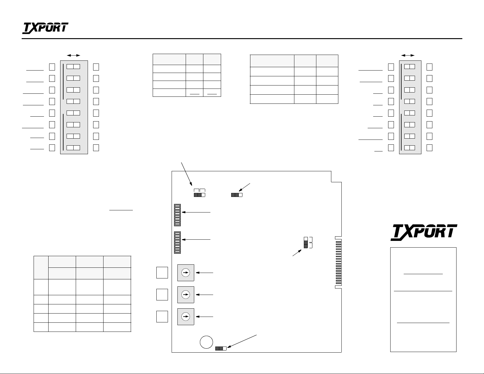
Switch S2 Power-up Mode TAPS Configurations Switch S3
Left Right
DTE/NET
Pass DL
NET/DTE
Pass DL
DTE/NET
Pass CRC
NET/DTE
Pass CRC
CARD
Master
ARM
from ROM
** A1
** A0
**
OPEN
See ‘Powe r-up Mode’
NOTE: For future reference, all DIP and rotary
switches on this shee t are provided wi th boxes to
check according to the particular user selection.
Factory default settings are shown underlined
12345678
DTE/NET
Block DL
NET/DTE
Block DL
DTE/NET
Regen CRC
NET/DTE
Regen CRC
CARD
Slave
ARM
from RAM
**
**
1557 TAPS Configuration Guide
** A0, A1
SWITCHES closed closed
RAM open closed
MANAGER closed open
ROM open
Service Select
BERG strap
J2
S2-7 S2-8
open
Configurations S2-5 S3-6
Transparent Slave Closed Closed
Normal Slave Closed Open
Transparent Master Open Closed
Normal Master Open Open
NOTE: TAPS units are always used in
pairs. One unit in the pair should be set
as ‘Master’ and the other set as ‘Slave’.
The two units shoul d always be co nfigured to the same mode, for example,
both ‘Normal’ or both ‘Transparent’.
CEEF
DISABLED
LOS
ENABLED
NET/B
AMI
NET/A
AMI
DTE
AMI
MODE
Normal Transp arent
REVERT
DISABLED
DTE
ESF
Part Number 45-00036
Left
Right
12345678
OPEN
Rev 2.0
CEEF
ENABLED
LOS
DISABLED
NET /B
B8ZS
NET /A
B8ZS
DTE
B8ZS
MODE
REVERT
ENABLED
DTE
D4
(front panel switch)
1557 APS CARD
Enabled
Disabled
123
.
S2
Power down option
(factory installed not to be removed)
Option Switch
J3
ASSY 1557 - 013
REV _________
S/N _________
®
DSX Rotary Switches
NET B NET A DTE
POS
SW1 SW2 SW3
3 0 - 133'
LIU*
0 - 133'
LIU*
0 - 133'
4 134 - 266' 134 - 266' 134 - 266'
5 267 - 399' 267 - 399' 267 - 399'
6 400 - 533' 400 - 533' 400 - 533'
7 534 - 655' 534 - 655' 534 - 655'
* If an LIU card is equipped, SW1
and SW2 must be set to position 3.
1
S3
Option Switch
NO
2
NC
3
J4
0
1
9
2
8
3
7
4
6
9
8
7
6
9
8
7
6
Network Line B DSX
5
0
1
2
3
4
Network Line A DSX
5
0
1
2
3
4
5
SW1
SW2
SW3
DTE Line DSX
Alarm Relay Mode
Default - NC
TRANSPORT
127 Jetplex Circle
Madison, Alabama 35758
Customer Service
800-926-0085, ext. 227
Product Technical Support
(8 a.m. to 5 p.m. Central)
205-772-3770, ext. 255
800-285-2755, ext. 255
Emergency After Hours
205-603-2193
Batt
J5 - RAM Battery
(factory installed not to be removed)
205-656-8318
Manager: 205-603-2194
Page 2

TRANSPORT
®
1557 Transparent Automatic Protection Switch (TAPS)
Part Number 45-00036
Rev 2.0
Background
The 1557 Transparent Automatic Protection Switch
(TAPS) is an enhanced version of TxPORT’s previous
automatic protection switch (APS) product. The TAPS
product has an additional mode of operation that was
not previously available. This mode is what ma kes this
new automatic protection switch ‘transparent’.
Earlier APS products were designed to protect T1
access lines from a central office to the customer. This
was accomplished by providing automatic switching to
a standby T1 circuit when the normal circuit was
deemed failed.
The 1557 card was used in a rack mounted configuration in the central office. The same 1557 card was a
component in a stand -alone unit for the customer end
of the circuit. Because of this dual use, the 1557 card
had to be configured for CO or CPE use. When configured for CPE, the 1557 card provided many of the features of an ESF CSU.
TAPS
The TAPS product is designed to provide the same type
of circuit protection but its transparent mo de allows the
user to deploy it in configurations other than CO-toCPE. Particularly, TAPS units are designed to protect a
T1 circuit between two central offices.
When configured for transparent mode, the TAPS unit
will not
mode, the TAPS unit will not enforce ones density
requirements, respond to inband loop codes, or respond
to 54016 performance messages. These enhancements
allow the TAPS u nit to be deployed in situations where
it is not required to serve as the network interface
equipment.
TAPS units configured for use as CPE do not generate
ANSI T1.403 performance report messages (PRM).
provide CSU type functions. In the transparent
This is true whether the selected mode is ‘transparent’ or
‘normal’.
Another feature of the TAPS product is a new switching
criterion. This parameter was added to enhance the TAPS
ability to efficiently detect incoming AIS and o ther severe
framing impairments. The new parameter is a measure of
Consecutive ESF Errored Frames (
defined as any frame with a CRC error or an OOF defect.
This CEEF parameter has a fixed threshold value. Once
this threshold is exceeded, the line is considered ‘failed’
as with any other APS switching parameter. The Line
Availability Timer and all other aspects of APS switching
apply to this parameter. The threshold value is set to 31.
This means that 93 ms o f AIS will typically cause a line
to be failed (because of hardware limitations, in some
cases 32 CEEFs are required to fail a circuit). This failed
condition is cleared when a non-errored frame is
received.
The standard TxPORT versions of the 1557 APS manual
and 1559 APSM manual still apply to the TAPS products.
CEEF
). A CEEF is
Configuration Details
Switch S3-6, previously defined as a spare, now has a
particular function for TAPS units. Switch S3 -6 is used to
configure the TAPS card mode as ‘normal’ or ‘transparent’. The drawings on the page below show how switch
S3 - 6 should be set for the two different implementations
of the TAPS unit. The settings apply to both the 15 57 APS
rack mount configuration and the 1558 APS stand- alone
configuration.
Since the TAPS card may now be used in a mode other
than CO-to-CPE, the meaning of switch S2-5 has
changed somewhat from the original APS version. Before,
this switch denoted which APS unit was CO and which
was CPE. The CO unit was the master of the two. It controlled status po lling and managemen t features. The CPE
unit was therefore the slave. With TAPS, the CO /CPE
relationship is not always valid but the Master /Slave
concept remains. Therefore, switch S2- 5 now denotes
whether a unit is a master or slave, regardless of where
the unit is physically located.
Note that in any pair of connected TAPS units, one unit
should be the master and one the slave. Both units
should be configured with the same mode selection,
either ‘Normal’ or ‘Transparent’.
Option switch S3-1, on the original APS units, was
used to enable or disable switching based on a single
out - of -frame (OOF) event. On TAPS un its, switch S3 -
1 is used to enable and disable the new CEEF parameter described above. TAPS units no longer support the
option to switch on a single OOF. (OOF is referred to as
LOF in the APS Manager and its associated documentation.)
1559 APS Manager
The APS Manager may still show the LOF parameter.
Configuration screens may still allow the LOF parameter to be enabled and disabled. In reality, this parameter
(shown as LOF) will be the new CEEF parameter. Setting LOF [OFF] or LOF [ON] in the manager will be
the equivalent of setting CEEF [OFF] or CEEF [ON]
respectively. If this parameter is set to [ON], the CEEF
parameter is enabled as a protection switching criterion.
When the 1559 APSM is used to control a TAPS unit,
some operations will function differently dependin g on
the mode of operation of the TAPS units. For instance,
if a TAPS unit is configured for the Transparent mode,
the ‘CSU Loop’ function of the APS Manager will not
cause any action. This is because the slave TAP S will
not respond to the inband loop codes. And, since the
loop codes cannot be sent on the ‘active’ line, this function cannot be used to loop a far end CSU.
Page 3
A
CPE
1
5
5
8
ACCESS
A
B
1
EQUIPMENT EQUIPMENT
5
IOC
5
7
1
5
5
7
ACCESS
1
CPE
5
5
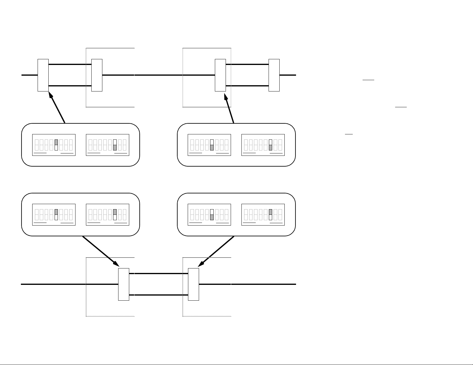
• TAPS units must
8
— CONFIGURATION NOTES —
be configured in pairs. In each
pair, one unit must be configured as a MASTER
and one as a SLAVE.
CO #1 CO #2
S2-5 closed
12345678
OPEN
Normal Slave
S2-5 closed
12345678
OPEN
S3-6 open
12345678
OPEN
S3-6 closed
12345678
OPEN
S2-5 open
12345678
OPEN
Normal Master
S2-5 open
12345678
OPEN
S3-6 open
12345678
OPEN
S3-6 closed
12345678
OPEN
Transparent Slave Transparent Master
IOC
CPE CPE
ACCESS
EQUIPMENT EQUIPMENT
1
5
A
5
7
B
1
5
5
7
B
CO #2CO #1
• Each pair of TAPS units must
be configured for
the same mode, NORMAL or TRANSPARENT
• A pair of TAPS units configured as NORMAL
may not
be placed in the same circuit with a pair
configured as TRANSPARENT.
• It is allowed (as the diagram shows) to have two
pairs of TAPS units on the same circuit if they are
configured for NORMAL mode.
• Take note of the setting for switches S2-7 and S2-
8. These switches determine the CONFIGURATION SOURCE for the 1557 card. Switch
options for Configuration Source are shown on
the front page of this document. The four choices
are explained in the 1557 Users Manual.
• A 1559 APS Manager connected to a 1557 configured as a MASTER unit can monitor and do
maintenance functions on both the master unit
and its corresponding slave unit.
• A 1559 APS Manager connected to a 1557 configured as a SLAVE unit can monitor only the
performance data for the slave unit. No maintenance functions are available through the slave
unit.
Page 4
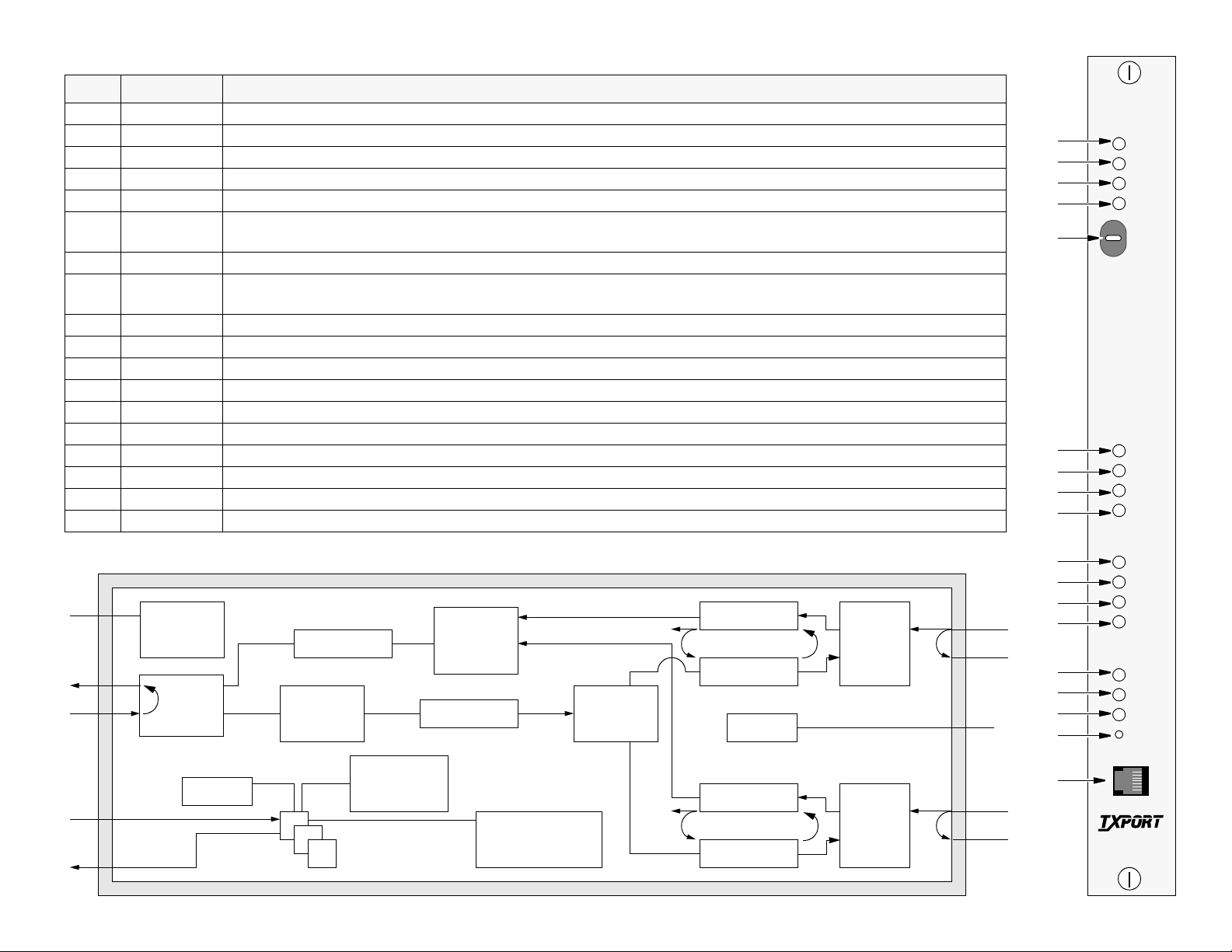
1557 Controls and Indicators
Index Indicator Description
STATUS
1 FAULT Indicates that the APS card has failed. Comes on briefly at power-up. (Yellow)
2 LOCK Indicates that the current path is ‘locked’ by the select switch or software command. (Yellow)
3 A Indicates that path A is carrying service. (Green)
4 B Indicates that path B is carrying service. (Green)
5 SERV SEL
AUTO/A/B
Moving this switch momentarily to A or B selects that line to carry service. Leaving the switch on A or B locks service to the
chosen line. This switch overrides all other commands. In normal operation, this switch should be left in the AUTO position.
PATH A/B
6 ALARM Indicates that the path is in alarm OR that an alarm condition has been cleared but the Line Availability Timer is running.
In either case, the path is NOT available for service. (Yellow)
7 PLB Indicates that the Payload Loop for the path is active. (Yellow)
8 LLB Indicates that the Line Loop for the path is active. (Yellow)
9 LOC LP Indicates that the Local Facility Loop for the path is active. (Yellow)
LOS
10 A RX Indicates that no signal is being received from Path A. (Yellow)
11 B RX Indicates that no signal is being received from Path B. (Yellow)
12 EQ RX Indicates that no signal is being received from the DTE. (Yellow)
MISC.
13 Bus Activity When flashes occur 2-3 seconds apart, indicates that messages are being received on the internal data bus.
14 Control Port This port jack currently has no function.
1557 Block Diagram
-48
VDC
EQUIP
NMS
IN
NMS
OUT
POWER
5/12 VDC
EQ
LB
INTERFACE
DTE PORT
DSX
LINE
(SW 3)
BERT
FRAMER
ONE’S
DENSITY
CPU
ROM
RAM
APS
SELECT
PATH A /B
DEFRAMER
LOOP
SET/RESET
PERFORMANCE/
A
B
ALARMS
A
SIGNAL
SPLIT
B
DEFRAMER
PLB
FRAMER
DEFRAMER
PLB
FRAMER
ALARM
FAC
LB
FAC
LB
DSX
LINE
INTER-
FACE
NET A PORT
(SW 2)
NETBPORT
(SW 1)
DSX
LINE
INTER-
FACE
LLB
LLB
NET A
NET B
10
11
12
13
14
STATUS
1
2
3
4
5
FAULT
LOCK
A
B
A
AUTO
B
SERV SEL
PATH A
6
7
8
9
ALARM
PLB
LLB
LOC LP
PATH B
6
7
8
9
ALARM
PLB
LLB
LOC LP
LOS
ARX
BRX
EQ RX
1
6
TRANSPORT
®
1557
 Loading...