

Page 1
TRANSPORT
1234567
SW1
®
1544N D4 CSU
Configuration Guide
M
Part Number 45-00016
Rev 1.01
N
O
®
TRANSPORT
NETWORK
INTERFACE
1544
T1 CSU
POWER
BPV
1
AIS
ALL 0’s
LOOP
DENSITY
SET
RESET
ERROR
M
N
O
TEST
NTWK
NORMAL
13128 9 10 11765432
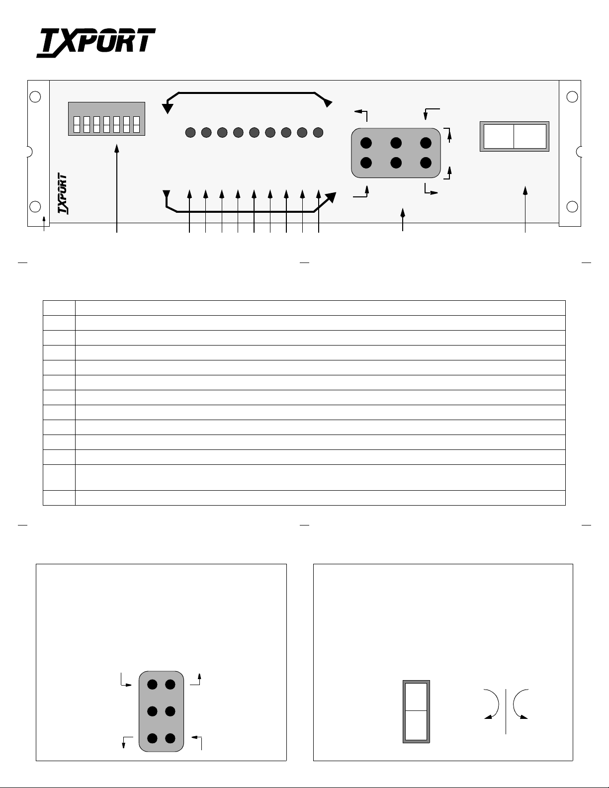
Front Panel Description
1 Brackets: Use the 2 holes on each bracket to bolt the 1544N to the rack mount kit or wall.
2 Switch SW1: This 7-position configuration switch is detailed on the reverse side of this guide.
3 POWER: This green LED lights whenever power is applied to the 1544N.
4 BPV: This red LED lights (0.1 seconds minimum) for each occurrence of bipolar violations (BPV).
5 ALL 0s: This red LED lights if no signal is detected from the network.
6 AIS: This red LED lights if an unframed all ones signal (alarm indication signal) is detected from the network or DTE.
7 LOOP: This yellow LED lights to indicate that the unit is in the Line Loopback condition.
8 DENSITY: This red LED lights if the ones density of the received data from the DTE is less than 12.5%.
9 SET: This red LED flashes when the set code is transmitted. It lights constantly if the set code is received.
10 RESET: This red LED flashes when the reset code is transmitted. It lights for 5 seconds if the reset code is received.
11 ERROR: This red LED flashes if an error is received during a network test.
12 Te s t J ac k s: These bantam jacks provide access t o the T1 line on the DTE sid e. The jacks allow transmit and rec eive toward the net-
work, toward the DTE, or monitoring of traffic between the DTE and the network. Refer to the description below.
13 Test Switch: This is a 3-position rocker switch used for performing a network test or a local loopback. Refer to the description below.
DTE
LOOP
LOCAL
Test Jacks (12) Test Switch (13)
TOP: The top 2 jack access ports break connecti on to the DTE
and make connection to the CSU in the direction of the network.
MIDDLE: The middle 2 ports are used for monitoring the signals passing through the CSU (between the DTE and the network).
BOTTOM: The bottom 2 ports break connection to the CSU and
make connection to the DTE.
Receive signal
from the network
Monitor signal
from the network
Transmit signal
to the DTE
Transmit signal
to the network
Monitor signal
from the DTE
Receive signal
from the DTE
NETWORK TEST: When depressed, the CSU loop code is transmitted for 5 seconds.
NORMAL: When moved from NTWK TEST back to NORMAL,
the CSU sends a loop do wn code. When moved from LOCAL LOOP
back to NORMAL, the local loop back is removed.
LOCAL LOOP: When depressed, t he C SU pe rfor ms a loca l, bi directional loop.
NTWK
TEST
NORMAL
LOCAL
LOOP
DTE NET
Page 2

1544N Rear P anel
1
8
LBO
NETWORK
0 dB
15 dB
7.5 dB
LBO Level
Sets the output signal level of transmitted data.
The Telco should provide the proper setting. If
unsure of the exact setting, set to 0 dB.
Option Switch SW1 (front panel)
Keep Alive - All Ones
Keep Alive - Unframed
Test Mode - BERT
Bipolar Violations - B8ZS
Test Pattern - Framed
Zeros - 15
Sealing Current - Off
7654321
RightLeft
TO
Keep Alive - Loop Back
Keep Alive - Framed
Test Mode - Clear
Bipolar Violations - AMI
Test Pattern - Unframed
Zeros - 50
Sealing Current - On
NETWORK
FROM
NETWORK
GROUND
-48 VDC
–
NOTE
+
TB1
: If the terminal block is to be used for DTE con-
1
DTE
DTETODTE
FROM
POWER
nection, the dummy plug must b e inserted into the DTE
jack. When the plug is removed, the unit is looped towar d
the network. There is no loop toward the DTE.
NET / DTE Interface
Pin DTE
(RJ48X)
1 Data Out Data In
2 Data Out Data In
3 Not used Not used
4 Data In Data Out
5 Data In Data Out
6 Not used Not used
7/8 Ground Ground
NET
(RJ48C)
8
: This unit is factory preset for normal operation. All factory default settings are shown under-
NOTE
lined. The unit may be installed a nd operated with out a ny fu rther a djus tment. If yo ur part icul ar setti ng
requir ements ar e dif fer ent, then mark the box which corr esponds to your selection (for futur e r efer ence).
Switch SW1 Description (front panel)
S1 Sealing Current: OFF is used where the Telco provides line power or where sealing current is not
required. ON applies sealing current to a dry (no power) Telco interface. Wa rning: enabling sealing
current with Telco line power present could damage the unit and/or cause improper operation.
S2 Zeros: 15
50 allows 50 zeros before Keep Alive is activated.
S3 Test Pattern: FRAMED indicates that the test signals (Set, Reset, and BERT) are framed.
UNFRAMED indicates that the test signals (Set, Reset, and BERT) are unframed.
S4 Bipo lar Violat io ns : AMI indicates a BPV error for each B8ZS event (if B8ZS coding is being used on
the network). B8ZS allows the CSU to be transparent to a B8ZS code coming from the network.
S5 Test M od e : CLEAR allows access to the network via test jack s to run bit error tests (effects network
tests only). BER T allows the CSU to send a bit error rate test pattern after the set signal (LOOP) is sent.
S6 Keep Alive: UNFRAMED transmits the Keep Alive signal without framing.
FRAMED adds framing information to the Keep Alive signal.
S7 Keep Alive: ALL ONES sends a consecutive sequence of all ‘1s’ back to the network.
LINE LOOP BACK sends any signal coming from the ne twork back to the network.
allows 15 successive zeros from the DTE before the Keep Alive mode is activated.
TRANSPORT
TxPORT
127 Jetplex Circle
Madison, Alabama 35758
Customer Service
800-926-0085, ext. 227
Product Technical Support
(8 a.m. to 5 p.m. Central)
205-772-3770, ext. 255
800-285-2755, ext. 255
Emergency After Hours
Support: 205-603-2193
Manager: 205 -603-2194
®
 Loading...