

Page 1

1051-2 Chassis
Configuration Guide
45-00050
3.0
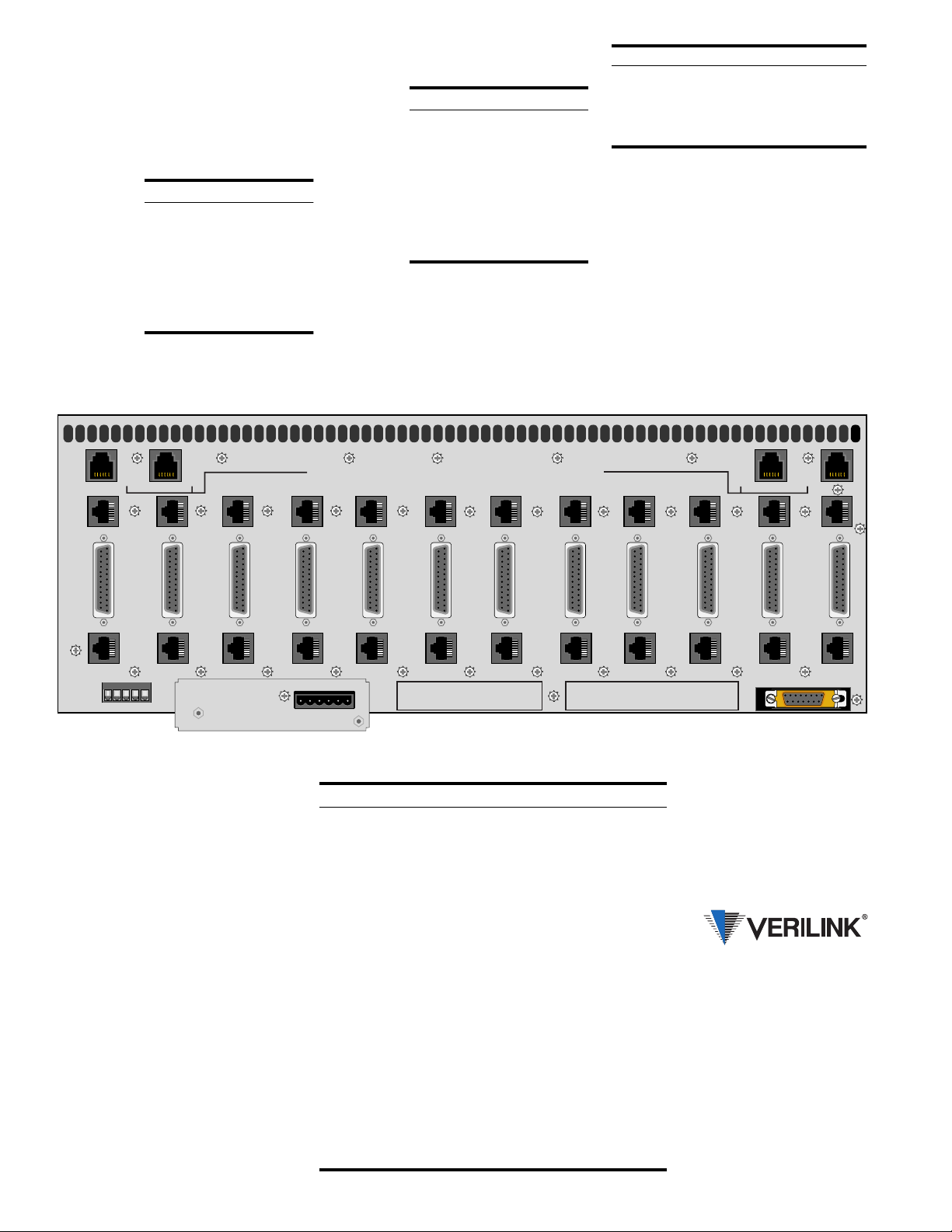
The Verilink 1051-2 chassis holds up to
twelve of the following modules:
2000 ESF CSU 3021 E1 NTU
2010 ESF CSU 4001 DDS CSU/DSU
2048 PMU / NTU 4010 DDS CSU/DSU
2100 CSU 4051 DDS CSU/DSU
3001 CSU / DSU 8100A Site Controller
Each module attaches to the chassis backplane board through two connectors. With
these connectors, each module receives −48
VDC power and exchanges control and input/
output signals. The chassis contains no active
components.
Specifications
Width: 17.2 inches (43.69 cm)
Height: 7 inches (17.78 cm)
Depth: 10.5 inches (26.67 cm)
Weight: 9.5 pounds (4.31 kg)
Opererating: 32° to 122°F (0° to 50°C)
Storage: −4° to 185°F (−20° to 85°C)
Humidity: 95% max (non-condensing)
Mounting: Reversible ears for 19-inch or
23-inch racks
ENET Connection
The Ethernet
interface is a female
15-pin D-shell
connector with
slide latch located
on the lower right
rear corner of t he
chassis .
Pin Interface
3 Data Out (A)
10 Data Out (B)
11 Data Out (Shield)
5 Data In (A)
12 Data In (B)
4 Data In (Shield)
2 Control In (A)
9 Control In (B)
1 Control In (Shield)
6 Voltage Common
13 Voltage Plus
14 Voltage S h ield
Shell Protectective Ground
Power Connections
The chassis is designed with two power buses
connected to TB2. The A bus feeds the odd
slots (1, 3, 5, 7, 9, and 11). The B bus feeds
the even slots (2, 4, 6, 8, 10, and 12). Connect
a Frame Ground lead (18- to 20-gauge) to
pin 2 before appl yin g power to the unit. Connect the other end of this lead to an appropriate frame ground.
Redundant Power Source: A power
board is factory installe d on TB2 allo wi ng the
connection of tw o ind ep e nd e nt −48 VDC
supplies operating in a redundant mode. All
slots are powered from the combined input of
the A and B power supplies. If one supply
fails, the other powers the entire chassis.
To operate in the redundant mode, connect
pins 3 and 4 (−48 V IN) on the redundant
power board to the negative (−) terminal of
the power supply. Connect pins 1 and 6 (+48
V RTN) to the positive (+) terminal of the
power supply.
Single Power Source: When using a sin-
gle power source, connect the A bus terminals (pins 4 and 6) on the redundant power
board to the corresponding termin als of the
power supply.
If the redundant power board is not used, the
A bus and B bus must be connected together
with a jumper (pin 3 to pin 4 and pin 1 to
pin 6).
Dual Power Source: When using dual in-
dependent 48 VDC power supplies, one
source feeds the A bus while another source
feeds the B bus. First, remove the redundant
power board. Connect the A bus (pins 4 and
6) to the corresponding terminals of power
supply A (to power the odd numbered slots).
Connect the B bus (pins 1 and 3) to the corresponding terminals of power supply B (to
power the even numbered slots).
The maximum cu r rent draw of a fully loaded
chassis is two amperes. The Verilink 1040
and 1041 power shelves can supply a maximum of two amps. Ensure that the proper fuse
size is used.
Page 2
NMS Connections
Cable Type Loss per 1000' Max Length
26-gauge 6.8 dB 3,900 ft
24-gauge 5.4 dB 5,000 ft
22-gauge 4.2 dB 6,400 ft
19-gauge 3.0 dB 9,000 ft
The NMS ports are used to connect the chassis into the 8100A Site Controller. Within the
chassis, each unit is physically connected to
the next unit in a daisy chain. Two 6-pin
modular connectors are provided for both the
A and B sides.
All units in the
chain must use
the same NMS
bit rate, however, each unit
in the NMS
chain must
have a unique
address.
Pin NMS In NMS Out
1 Not Used Not Used
2 Signal Gnd Signal Gnd
3 Data Out Data Out
4 Data In Not Used
5 Si gna l Gnd S i gnal Gnd
6 Not Used Not Used
Network and DTE
Connections
The T1 DTE
and T1 NET
ports are 8-
pin modular
jacks. The
maximum
suggested
cable lengths
for chassis
connection
to the network are listed in the following table. These
distance s are based on a temperature of 70 °F,
0.083 µF/mile capacitance, a 27 dB loss, and
a 100 Ω, non-loaded, twisted pair cable.
Pin T1 DTE T1 NET
1 Data Out Data In
2 Data Out Data In
3 Not Used Not Used
4 Data In Data Out
5 Data In Data Out
6 Not Used No t Used
7, 8 Signal Gnd Signal Gnd
Alarm Connections
Alarm conditions from all modules in the
chassis are bused together in parallel and are
presented on a single set of alarm relay contacts (TB1, pins 3 and 4) allowing connection
to a remote indicating devi ce. All modu le s in
a common chassis must operat e in th e normally open (NO) mode.
Connections to the contacts should use 20gauge stranded wire (or similar). The contacts
are rated at 120 mA (AC or DC).
( B )
NMS
OUT
T1
11
T1
11
TB2
NET
HIGH
SPEED
DTE
10
NET
T1
10
T1
10
HIGH
SPEED
DTE
12
NET
NET
( B )
NMS
IN
T1
12
T1
12
TB1 -
HIGH
SPEED
DTE
1 2 3 4 5
NET
11
NET
External Clock
Connections
TB1 provides the contacts allowing connection to an external timing source (pins 1
and 2).
High-Speed DTE
Connections
The high-speed port connections use a
female 25-pin subminiature DB-25 connector. The pin interface comparisons are detailed in the table on the right.
If the unit is connected to an EIA-530 DTE
type device, only a one-to-one DB-25 cable
is required.
If the unit is connected to an RS-449 compatible interface, an adapter cable must be
used to match the 37-pin RS-449 standard.
The V.35 option also requires an appropriate
adapter cable to connect to devices that use
the standard 34-pin V.35 interface.
NMS A & NMS B, IN AND OUT, ARE NON-TELECOM (T1) CONNECTORS
Les portes d'entree/sortie NMS A & NMS B sont des connecteurs non-telecommunication (T1)
NET
HIGH
SPEED
DTE
9
NET
T1
9
T1
9
TB2 -
HIGH
SPEED
DTE
8
1 2 3 4 5 6
2.4 AMPS
NET
NET
T1
8
T1
8
T1
NET
7
HIGH
SPEED
DTE
7
T1
NET
7
1 - EXT CLK
TB1
2 - EXT CLK
3 - ALARM RING
HIGH
SPEED
DTE
6
NET
NET
T1
6
T1
6
4 - ALARM TIP
5 - SIG GND
HIGH
SPEED
DTE
5
NET
NET
T1
5
T1
5
HIGH
SPEED
DTE
4
1 - +48V RTN ( B )
TB2
2 - FRAME GND
3 - -48V IN ( B )
NET
NET
T1
T1
Common Name DB-25 EIA-530 RS-449 V.35
Frame Ground 1 1 1 A
Signal Ground 7 7 19 B
Transmit Data (A) 2 2 4 P
Transmit Data (B) 14 14 22 S
Receive Data (A) 3 3 6 R
Receive Data (B) 16 16 24 T
Request to Send (A) 4 4 7 C
Request to Send (B) 19 19 25
Clear to Send (A) 5 5 9 D
Clear to Send (B) 13 13 27
Data Set Ready (A) 6 6 11 E
Data Set Ready (B) 22 22 29
Data Term Ready (A) 20 20 12 H
Data Term Ready (B) 23 23 30
Data Carrier Detect (A) 8 8 13 F
Data Carrier Detect (B) 10 10 31
Transmit Clock (A) 15 15 5 Y
Transmit Clock (B) 12 12 23 AA
Receive Clock (A) 17 17 8 V
Receive Clock (B) 9 9 26 X
Terminal Timing (A) 24 24 17 U
Terminal Timing (B) 11 11 35 W
( A )
NMS
IN
T1
NET
4
4
3
HIGH
SPEED
DTE
3
T1
NET
3
4 - -48V IN ( A )
5 - SIG GND
6 - +48V RTN ( A )
NET
HIGH
SPEED
DTE
2
NET
T1
2
T1
2
( A )
NMS
OUT
HIGH
SPEED
DTE
1
ENET
NET
NET
T1
1
T1
1
145 Baytech Drive
San Jose, California 95134
127 Jetplex Circle
Madison, Alabama 35758
(800) 837-4546
www.verilink.com
FAX-On-Demand
(800) 957-5465
Techn i cal Assistance Center
(800) 285-2755
 Loading...