

Page 1
Omni 3210
Installation Guide
Page 2

IMPORTANT NOTI CE
Lithium Battery Caution. The Random Access Memory (RAM) in the Omni
3210 terminal is protected by a lithium battery. Do not, under any
circumstances, attempt to replace this battery. Failure to comply may void the
product warranty.
No Warranty. Although VeriFone has attempted to ensure the accur ac y and
completeness of its cont e nts, thi s manual may contai n errors or omissions.
Limited Liability . In no event shall V eriFone be liable for any indirect,
special, incidental, or consequential damag es ( including damages for loss of
business, profits or the like), even if VeriFone or its represent atives have been
advised of the possibilit y of suc h dam a ge s.
Product Changes. VeriFone reserves the right to change, update, or make
obsolete any product changes at any time and without notice.
Document Title: Omni 3210 Installatio n G ui de
VeriFone Part Number: 21920, Revision A
Copyright © 2001 VeriFone, Inc.
All rights reserved.
Printed in the United States of America.
No part of this public at io n may be copied, distributed, stored in a retrieval
system, translated into any human or compute r la nguage, transmitted, in any
form or by any mean s, without the prior written co nse nt of VeriFone.
VeriFone, the VeriFone logo, Omni, S of tPay, and VeriT alk are either
trademarks or registered trademarks of VeriFone in the United States and/or
other countries.
All other brand names, trademarks, or service marks are the properties of their
respective owne rs.
Page 3

Omni 3210 Installation Guide
Table of Contents
Introduction . . . . . . . . . . . . . . . . . . . . . . . . . . . . . . . . . . . . . . . . . . .5
Installing the Omni 3210
Step 1: Select a Location for the Terminal . . . . . . . . . . . . . . .7
Step 2: Unpack the Shipping Carton . . . . . . . . . . . . . . . . . . . .8
Step 3: Examine Terminal Features . . . . . . . . . . . . . . . . . . .10
Step 4: Connect the Terminal to a Telephone Line . . . . . . . .13
Step 5: Connect Optional Device(s) . . . . . . . . . . . . . . . . . . .18
Step 6: Connect the Terminal Power Pack . . . . . . . . . . . . . .23
Step 7: Install a Paper Roll in the Printer . . . . . . . . . . . . . . . 25
Maintaining the Omni 3210
Cleaning the Terminal . . . . . . . . . . . . . . . . . . . . . . . . . . . . . .30
Cleaning the Printer . . . . . . . . . . . . . . . . . . . . . . . . . . . . . . .30
Troubleshooting . . . . . . . . . . . . . . . . . . . . . . . . . . . . . . . . . . . . . . .31
VeriFone Service and Support . . . . . . . . . . . . . . . . . . . . . . . . . . . .35
Returning a Terminal for Service . . . . . . . . . . . . . . . . . . . . . . . . . .36
Specifications . . . . . . . . . . . . . . . . . . . . . . . . . . . . . . . . . . . . . . . . .38
Accessories . . . . . . . . . . . . . . . . . . . . . . . . . . . . . . . . . . . . . . . . . . .39
How to Order . . . . . . . . . . . . . . . . . . . . . . . . . . . . . . . . . . . .39
3
Page 4

Omni 3210 Installation Guide
4
Page 5

Introduction
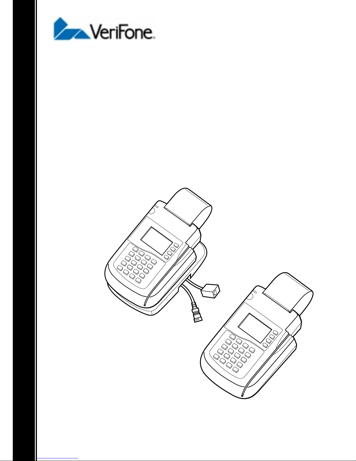
The new Omni 3210 terminal from VeriFone expands the
capabilities of the popular Omni 3200 terminal with the
additi on of an internal PI N pad for processi ng debit,
electronics benefits transfer (EBT), and other PIN-based
transactions (see Figure 1).
Omni 3210 Installation Guide
Figure 1 Omni 3210 Point-of-Sale Terminal
The Omni 3210 terminal’ s internal PIN pad eliminates th e need
to purchase and connect an external PIN pad, and also saves
valuable countertop space. An optional swivel stand facilitates
PIN entry by allowing the Omni 3210 to serve as both a clerkfacing and customer-facing entry device (see Figure 2).
To help ensure the security of PIN-based transactions, the
Omni 3210 incorporates advanced tamper-resistance features,
in addition to widely-used data encryption metho ds and key
manage ment sche mes.
5
Page 6
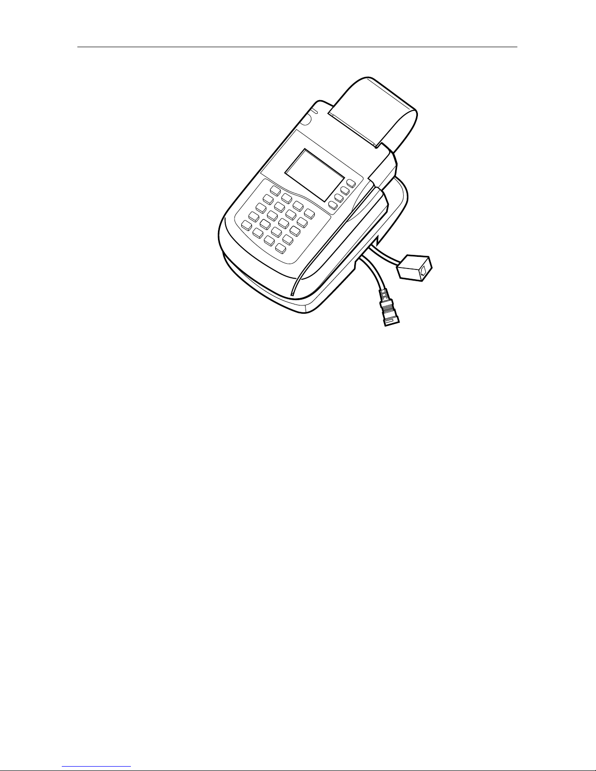
Omni 3210 Installation Guide
Figure 2 Omni 3210 Terminal with Swivel Stand
The Omni 3210 terminal is attractive, compact, easy to learn
and use, and very reliable. In addition to the integrated PIN
pad, its important features include:
• an intuitive, ATM-style interface,
• a large, back-lit display with graphics capability,
• a high-speed, integrated thermal printer,
• a triple-track magnetic stripe card reader,
• two telephone ports to eliminate the expense of a second
phone line,
• advanced fraud protection features, and
• the industry’s best warranty.
The Omni 3210 supports the full line of VeriFone peripherals,
including check readers, smart card readers, bar-code wands,
and even external PIN pads, to process almost any type of
point-of-sale transaction.
6
Page 7

Omni 3210 Installation Guide
Installing the Omni 3210
Step 1: Select a Location for the Terminal
T o select the best location for your Omni 3210 terminal, follow
these important guidelines:
Ease of Use
Select a location that contributes to the terminal’s ease of use:
• A location convenient for both merchant and cardholder.
• A flat support surface, such as a countertop or table.
• Proximity to a power outlet and a modular RJ-11 type
telephone line connecti on.
Note: If you are using the Omni 3210 with optional swivel
stand, make sure there is enough space on the countertop or
table so the clerk/cashier can rotate the terminal freely on the
stand to allow cardh ol ders to eas il y enter t h ei r PIN num ber f or
debit-type transactions.
Environmental Considerations
Caution: Do not plug the pow er pack into an outdoor outlet or
operate the terminal outd oors. It is not waterpr oof or dustproof,
and is for indoor use only. Any damage to the unit from
exposure to rain or dust may invalidate the product warranty!
Do not use the terminal where there is high heat, dust,
humidity, moisture, or caustic chemicals or oils. Keep the
terminal away from direct sunlight and anything that radiates
heat, such as a stove or a motor.
7
Page 8

Omni 3210 Installation Guide
Electrical Considerations
Caution: Due to risk of electrical shock or damage to terminal
components, do not use the terminal near water, including a
bathtub, wash bowl, kitchen sink or laundry tub, in a wet
basement, or near a swimming pool. Avoid using this product
during electrical storms.
Avoid locations near electrical appliances or other devices that
cause excessive voltage fluctuations or emit electrical noise
(for example, air conditioners, neon signs, high-frequency or
magnetic security devices, or electric motors).
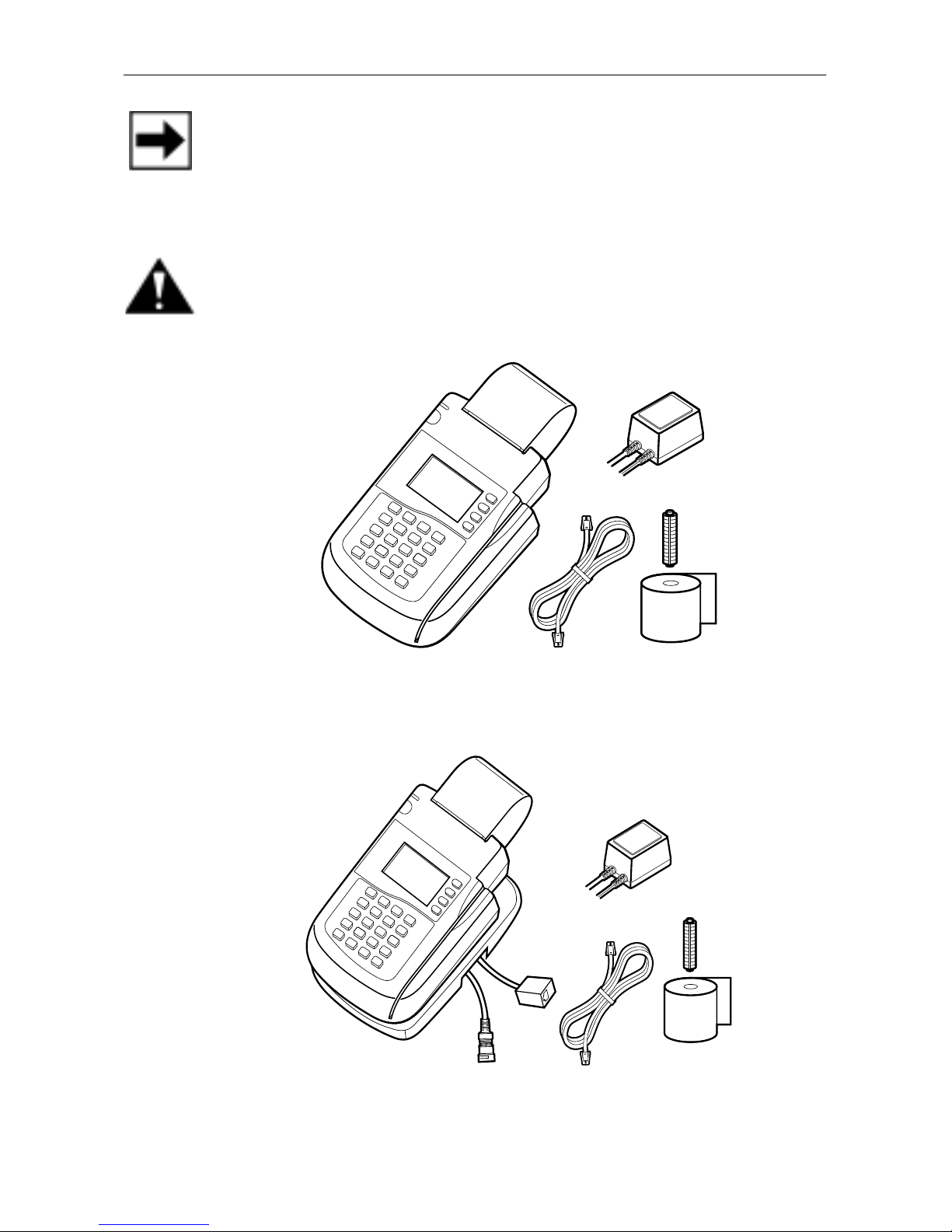
Step 2: Unpack the Shipping Carton
Carefully inspect the Omni 3210 shipping carton and its
contents for any damage or tampering (see Figure 3 and
Figure 4). To unpack the shipping carton:
1. Remove and inspect the following items:
• Omni 3210 terminal (standard model or with optional
swivel stand and two “pigtail” cables attached)
• Power pack (AC adapter and attached cables)
• Telephone line cord
• Roll of thermal printer paper
• Plastic paper roll spindle
2. Remove protective wrapping from the terminal and other
components and arrange them on a table or countertop.
3. Peel off the clear pr otective strip that co vers the terminal’s
display screen.
4. Save the shipping carton and packing material for
repacking or moving the terminal in the future.
8
Page 9
Omni 3210 Installation Guide
Note: If the terminal or any product component appears
damaged or to have been tampered with, immediately notify
the shipping company and your VeriFone distributor or service
provider.
Caution: Do not use a terminal that has been damaged or
tampered with.
Figure 3 Omni 3210 Components
Figure 4 Omni 3210 with Swivel Stand Components
9
Page 10

Omni 3210 Installation Guide
Step 3: Examine Terminal Features
Before you continue the installation, please take a moment to
note the important features of the Omni 3210, as shown in
Figure 5 below.
Power-On/ Paper Detect
LED Indicator
Paper Feed Button
Display
Telco-Style Keypad
Figure 5 Features of the Omni 3210 Terminal
Printer
Magnetic Stripe
Card Reader
ATM-Style Keys
Application-Specific
Function Keys
Color-Coded
Function Keys
General Features
W ith the Omni 3210 terminal lying o n a flat surface and facing
toward you, you will notice the following features:
• In the center of the terminal, a display screen with a non-
removable, clear protective lens.
• 24 keys, arranged in groups (see Figure 5):
– A 12-key, telephone-style keypad
– Eight function keys (four to the right of the 12-key
keypad, and four above the keypad)
– Four ATM-style keys to the right of the display
10
Page 11

Omni 3210 Installation Guide
• A magnetic stripe card reader, built in to the
right side of the terminal. A graphical icon,
shown to the right, indicates the proper card
position and swipe direct i on (see Fi gure 6).
Figure 6 Using the Magnetic Stripe Card Reader
• A thermal pri nter, integrated into the upper
part of the terminal. In the top left corner of the
terminal is a small, green “power-on” and “no
paper” indicator li ght , and a pap er feed but to n.
An icon, shown to the right, indicates the
location and function of the paper feed button.
Connection Ports on the Back Panel
If you turn the terminal around and view it from the back,
looking below and to the right of the paper roll holder, you will
notice five modular jacks, or ports (see Figure 7). These ports,
described in left-to-right order below, let you connect the Omni
3210 to a tele phone line, up to two o ptiona l peri pherals, and an
electrical power source.
11
Page 12

Omni 3210 Installation Guide
Card
Reader
Slot
Power Port
Telset Port
Telco Port
Figure 7 Omni 3210 Connection Ports
Bar Code /
PIN Pad Serial Port
RS232 Serial Port
Telephone Line Ports
• On the left side of the back panel are two RJ-11 type
modular jacks for connecting the terminal to a telephone
line:
The first port is identified by a telephoneshaped “Telset” icon, shown to the right. You
use the T e lset port to connect th e Omni 321 0 to
a telephone base unit to configure an optional
pass-through telephone line connection.
The second telephone line port is identified by
a jack-shaped “Telco” icon, shown to the right.
You use the Telco port to connect the Omni
3210 directly to a modular telephone wall jack.
Ports for Attaching Optional Peripherals
• There are two R J -45 type modular jacks (serial ports) fo r
connecting optional peripheral devices:
12
Page 13

Omni 3210 Installation Guide
The first serial port is identified by the
“RS232” icon shown to the right. You use the
RS232 port to connect a VeriFone CR 600
check reader, or a similar type of serial device.
The second serial port is identified by “Bar
Code” and “PIN Pad” icons, shown to the
right. You use t he Bar Code/PIN Pad port to
connect a PIN pad, smart card reader/writer, or
bar code wand.
Power Pin Connector Port
• On the lower right-hand side of the back of the
terminal is a port for conn ecting the terminal to
a power source. The Power port is identified
by the “electrical power” icon shown to the
right.
Step 4: Connect the Terminal to a Telephone Line
You can connect the Omni 3210 to a telephone line in one of
two ways — direct or pass-through. The relative advantages
and disadvantages of t hese t wo t yp es o f t el epho ne con nect ion s
are described below.
About Direct Telephone Line Connections
With a direct telephone line connection, a single telephone line
cord connects the Telco port on the back of the terminal
directly to a nearby RJ-11 type modular telephone company
wall jack (see Figure 8). A direct connection is usually
preferred because telephone line usage is dedicated to the
terminal, making it possible to perform an electronic
transaction at any time.
13
Page 14

Omni 3210 Installation Guide
Figure 8 Direct Telephone Line Connection
About Pass-Through Telephone Line Connections
With a pass-through connection, the terminal uses a telephone
line that is shared by a standard telephone base unit (see
Figure 9). A pass-through telephone line connection is useful
when you want to save the cost of an additional dedicated or
leased line. There are, ho wever, several disadvantages to using
a pass-through connection:
• You cannot make a normal call while the terminal is
processing a transaction, or when a remote host computer
is dialing in to the terminal.
• Lifting up the telephone handset during a transaction may
disrupt the audible data carrier signal and cause the
terminal transaction to fail.
• T w o telephone li ne cords are required i nstead of one. (One
telephone line cord is supplied with the terminal; you can
obtain an extra cord from VeriFone or from any local
business supply store .)
14
Page 15

Omni 3210 Installation Guide
RJ-11 T ype
Modular Wall Jack
Telset Port
Figure 9 Pass-Through Telephone Line Connection
Telco Port
Telephone
RJ-11 T ype Jack
in T elephone Base
Now that you know t he ad vantages and di sadvan tages of direct
and pass-through telephone line connections, you can proceed
to install the type of connection you want.
Set Up a Direct Telephone Line Connection
To set up a direct telephone line connection for your Omni
3210 terminal, follow these steps (refer to Figure 8):
1. Insert the connector on one end of the
telephone line cord into the Telco port on the
back panel of the terminal. (The Telco port is
identified by the icon shown to the right.)
15
Page 16

Omni 3210 Installation Guide
2. Insert the connector on the other end of the cord into a
nearby RJ-11 type telephone company wall jack. (If you
do not have this type of modular wall jack, you can obtain
an adapter from a local business supply store.)
Set Up a Pass-Through Telephone Line Connection
To set up a pass-through telephone line connection using two
telephone line cords, follow these steps (refer to Figure 9):
1. Insert the connector on one end of the first
telephone line cord into the Telco port on the
back panel of the terminal. (The Telco port is
identified by the icon shown to the right.)
2. Insert the connector on the other end of the first telephone
line cable into a nearby RJ-11 type telephone company
wall jack.
3. Insert the connector on one end of the second
telephone line cable into the Telset port on the
back panel of the terminal. (The Telset port is
identified by the icon shown to the right.)
4. Insert the connector on the other end of the second
telephone line cable into a RJ-11 type modular jack
located on the back or side of a nearby standard telephone
base unit.
Caution: If you have chosen to use a pass-through connection
for your terminal, do not attempt to make a normal telephone
call while the terminal is processing a transaction. Lifting up the
handset may disrupt the aud ible data carrier signal and caus e the
transaction to fail.
16
Page 17

Omni 3210 Installation Guide
Setting Up Telephone Line Connections for Omni
3210 Terminals with Attached Swivel Stand
An optional swivel stand is available
for the Omni 3210 terminal. Many
terminals come with the swivel stand
already attached, as shown to the
right, and with two pre-installed
“pigtail” cables that let you
conveniently connect the power
cable and telephone line cord.
The telephone line pigtail lets you conveniently configure a
direct telephone line connection without removing the swivel
stand. To set up a direct connection using the pigtail cable:
1. Insert the connector on one end of the telephone line cord
into the modular RJ-11 type jack located inside the squareshaped “female” end of the telephone line pigtail.
2. Insert the connector on the other end of the cord into a
nearby RJ-11 type telephone company wall jack.
To configure a pass-through connection for a terminal with
attached swivel stand, you must remove the stand in order to
properly connect and route the two telephone line cords, and
then re-attach the stand to the terminal.
Note: The procedure for removing and reattaching the swivel
stand is described in the Omni 3XXX Swivel Stand Quick
Installation Guide (VeriFone Part Number 21919).
17
Page 18

Omni 3210 Installation Guide
Step 5: Connect Optional Device(s)
The Omni 3210 supports the complete line of VeriFone
peripheral devices designed for use with electronic point-ofsale terminals. For complete information about how to install
and use a peripheral, please refer to the user documentation
supplied with that device.
Using the two RJ-45 type serial ports on the back panel of the
terminal (the RS232 port and the Bar Code/PIN Pa d port ) , you
can connect up to two optional devices to the terminal.
Optional devices available from VeriFone include check
readers, smart card reader/writers, bar code wands, external
PIN pads, and an external printer. Brief descriptions of how to
connect various devices to the Omni 3210 are provided below.
Caution: Before connecting any peripheral device, turn off
power to the terminal. T urn on power only after you are finis hed
connecting the peripheral device(s).
Connecting an Optional Peripheral to an Omni 3210
Terminal with Attached Swivel St and
To connect an optional peripheral to an Omni 3210 terminal
with an attached swivel stand, you must:
1. Remove the swivel stand,
2. Connect and route the additional serial cable through the
guides in the swivel stand, and
3. Reattach the swivel stand to the terminal.
Note: The procedure for removing and reattaching the swivel
stand is described in the Omni 3XXX Swivel Stand Quick
Installation Guide (VeriFone Part Number 21919).
18
Page 19

Omni 3210 Installation Guide
Connect a CR 600 Check Reader
Caution: Some peripherals require a separate power source.
Before connecting a CR 600 check reader or sim ilar device, turn
off power to the terminal.
To connect a CR 600 check reader (see Figure 10):
1. Insert the round mini-DIN type connector on one end of
the serial cable into the TERM. (i.e. Terminal) port on the
back of the check reader.
2. Insert the RJ45-type connector on the other end of the
serial cable into the RS232 port on the back panel of the
Omni 3210 terminal.
3. Connect the check reader power pack to a power outlet.
4. Insert the round barrel-type connector into the power port
on the lower back panel of the check reader.
Figure 10 CR 600 Check Reader Connection
19
Page 20

Omni 3210 Installation Guide
Connect a Smart Card Reader/Writer or PINpad 501
To connect a VeriFone SC 4XX or SC 5XX smart card reader/
writer, or a PINpad 501, to the Omni 3210 terminal (see
Figure 11):
1. If a serial cable is not already connected to the smart card
reader/writer or P INpad 501, insert the RJ -11 type plug on
one end of the cable into the modular jack on the device.
2. Insert the larger RJ-45 type plug on the other end of the
serial cable into the Bar Code/PIN Pad port on the back
panel of the Omni 3210 terminal.
Figure 11 SC 4XX, SC 5XX, and PINpad 501 Connection
Connect a Bar Code Wand
To connect an optional bar code wand, insert the RJ-45 type
plug on the free end of the device’s serial cable into the Bar
Code/PIN Pad port on the back panel of the Omni 3210
terminal (see Figure 12).
20
Page 21

Omni 3210 Installation Guide
Figure 12 Bar Code Wand Conne ction
Connect an External PIN Pad
The Omni 3210 terminal comes with an internal PIN pad. In
some cases, however , it may be necessary to install an external
PIN pad to use instead of, or in addition to, the internal PIN
pad, if necessary (see Figure 13 and Figure 14).
To connect an external PIN pad to the Omni 3210 terminal:
1. If necessary, insert the small RJ-11 type modular plug on
one end of the PIN pad cable into the modular jack on the
PIN pad.
2. If you are installing a VeriFone PINpad 101, PINpad 201,
or PINpad 1000 , pos ition and i nsert t he gr ommet t o secur e
the cable connection (see Figure 13).
3. Insert the larger RJ-45 type connector on the other end of
the PIN pad cable into the Bar Code/PIN Pad port on the
back panel of the Omni 3210 terminal.
21
Page 22

Omni 3210 Installation Guide
Figure 13 PINpad 101/102/1000 Connection
Figure 14 PINpad 201/301/2000 Connection
Connect an External VeriFone Printer
The Omni 3210 terminal comes with an integrated thermal
printer. The Omni 3210 can also support an external VeriFone
printer — the Printer 250. This external printer can be used in
addition to, or instead of, the integrated printer to meet the
requirements of the terminal application.
22
Page 23

Omni 3210 Installation Guide
Note: To connect a Printer 250, a custom interface cable is
required. The specifications for this cable are published in the
Omni 3200/3210 Reference Manual (VeriFone Part Number
22295).
Step 6: Connect the Terminal Power Pack
When you have finished connecting any optional peripheral(s),
you are ready to connect the Omni 3210 to a power source:
Caution: When connecting the terminal to a two-cable power
pack, always connect the three-pronged plug of the power pack
to an electrical wall outlet first. Then insert the round connector
on the end of the other power pack cable into the terminal’s
Power port.
1. Plug the three-p ron ged plug on the end of one power pack
cable into an electrical power outlet (see Figure 15).
Note: To protect your terminal against possible damage
caused by lightning strikes an d electrical su rges, you may wish
to install a power surge protector at the power outlet.
2. Insert the round female type connector on the
end of the other power pack cable into the
Power port on the back of the terminal (see
Figure 15). The Power port is identified by the
icon shown to the right.
Note: The round female type connector on the end of the
power cable is a lock-type device that is designed to prevent
the cable from accidentally being disconnected from the
terminal:
23
Page 24

Omni 3210 Installation Guide
To insert the end of the connector into the
Power port, align the connector so the plastic
locking part that pr ojects fr om the connector i s
pointing upward. When the connector is in
position, twist it to the left, as indicated by the
word “LOCK” on the connector, and toward
the “locked” icon on the left side of the power
port. The “locked” icon is shown to the right.
To remove the power cable from the terminal,
and to disconnect the terminal from its power
source, turn the connector to the right (toward
the “unlocked” icon on the upper right of the
power port) and remove it from th e Power port.
The “unlocked” icon is shown to the right.
Figure 15 Omni 3210 Power Pack Connection
When you have established the power connection to the Omni
3210 terminal, the dis play screen, and the green LE D at the top
left corner of the terminal, light up. (This LED should now be
24
Page 25

Omni 3210 Installation Guide
flashing off and on, indi cati ng that there is no paper in the
printer.)
Caution: The AC adapter on the Omni 3210 power pack is
designed to ensure your personal safety and to be compatible
with this equipment. Please follow these guidelines:
• Do not use the adapter in a high moisture environment.
Never touch the adapter when your hands or feet are wet.
• Allow adequate ventilation around the adapter. Avoid
locations with restricted airflow.
• Connect the adapter to a proper power source. The voltage
and grounding req uirements are fou nd on the pro duct case
and/or packaging.
• Do not use the adapter if the cord becomes damaged.
• Do not attempt to service the adapter. There are no
serviceable parts inside. Replace the unit if it is damaged
or exposed to excess moisture.
Caution: Disconnecting power during a transaction may cause
transaction data files that are not yet stored in terminal memory
to be lost.
Step 7: Install a Paper Roll in the Printer
A fast, quiet thermal printer is built in to the Omni 3210.
Because the printer receives power directly from the terminal,
there are no additional cables to connect (see Figure 16).
Before you can process transactions that require a receipt or
record, you must install a roll of thermal-sensitive paper in the
printer . This procedure is described in “Installing a Paper Roll”
on page 27.
25
Page 26

Omni 3210 Installation Guide
About Thermal Printer Paper
The Omni 3210 printer uses single-ply, thermal-sensitive roll
paper that is 58 millimeters (2.25 inches) wide and about
25 meters (82 feet) long.
Because the paper roll size is standard, you can purchase
thermal paper in bulk from local business supply stores. You
can also order thermal printer paper directly from VeriFone
(see “Accessories” on page 39).
Here are some things to remember about the thermal paper
rolls that you use in the Omni 3210 printer:
• Store thermal paper in a dry, dark area. Handle thermal
paper carefully: impact, friction, temperature, humidity,
and oil affect the color and storage characteristics of the
paper.
• Never load a roll of paper with folds, wrinkles, tears, or
holes at the edges or in the printing area. For best results,
cut a straight edge on the paper with scissors before
feeding it into the printer.
• Poor-quality paper may jam the printer. Always use highquality thermal paper, which can be ordered from
VeriFone, if it is not available locally.
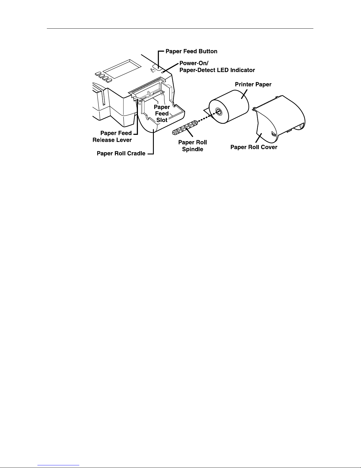
Before you proceed with installing a paper roll, please
familiarize yourself with the various features of the printer, as
shown in Fi gure 16.
26
Page 27
Omni 3210 Installation Guide
Figure 16 Thermal Printer Features
Installing a Paper Roll
To install a roll o f therm al prin ter pape r in th e Omni 3 210 :
1. Be sure the terminal is connected to a power source. (The
green LED “paper out” light should be blinking off and
on, indicating that the printer needs paper.)
2. With the terminal on a flat surface and facing toward you,
remove the paper ro ll cover fr om the to p of the t erminal by
lifting up on the back of the cover. The two ridges on each
side of the black plastic cover show you where to grasp it.
3. Remove the protective strip from a new roll of paper and
cut a clean, straight edge on the leading end of the paper.
4. Holding the roll in your hand with the paper feeding from
the bottom of the roll, slowly insert the leading end into
the paper feed slot (refer to Figure 1 6). When the built-in
sensor detects the paper, the feed mechanism engages and
pulls the paper into the printer, ejecting the end of the
paper from the top of the printer over the top of the paper
roll cover.
27
Page 28

Omni 3210 Installation Guide
Note: The paper feed slot is located directly above the gray
plastic paper roll cradle, and below the black plastic ridge that
extends slightly from the base of the paper feed mechanism
(refer to Figure 16).
5. If necessary, hold down the paper feed button until about
five centimeters (two inches) of paper emerge from the
slot below the serrated metal tear strip.
6. Insert the orange plastic spindle into the hole in the paper
roll you are holding. Then, place the spindle and roll into
the paper roll cradle so the ends of the plastic spindle rest
securely in the two slots.
7. Replace the paper roll cover by inserting its two front tabs
into the slots on either end of the serrated metal strip and
then lightly pushing down on the back of the cover until it
snaps into place.
(Remember to lift up the end of the paper roll when
replacing the paper roll cover so that the paper rests on top
of the cover.)
Note: The integrated thermal printer has a paper feed release
lever that lets you manually adjust the position of the paper
you have loaded into the printer (refer to Figure 16). T o do this,
lift up on the small red lever located on the right side of the
paper roll cradle until it snaps into its “Up” position. You can
now free ly move the paper up and down through the feed
mechanism. When the paper is in the correct position, lower
the lever until it snaps back into its “Down” position.
Performing a Power-On Printer Test
When you have installed a paper roll, you can perform a quick
test to make sure the thermal printer is operating correctly:
28
Page 29

Omni 3210 Installation Guide
1. T emporar ily disconnect the terminal from its power source
by removing the power connect or from the Powe r port on
the back panel. (Twist the connector to the right to unlock
it and then pull it straight out.)
2. While pressing — and holding down — the paper feed
button, insert the power connector back into the power
port, twisting the connector to the left to lock it into
position. The printer test starts automatically, and then
stops after a few seconds.
3. When you see the test printout, release the paper feed
button. The complete test printout, which shows print er
information and repeating character strings of various
sizes, is about 38 centimeters (15 inches) long.
4. When you have compl eted the p ower -on printer t est, pres s
the paper feed button to advance the paper roll a few
centimeters (inches) and then tear off the printout using
the serrated metal tear strip.
Congratulations! Your Omn i 3210 terminal, and any optional
peripheral device(s) you may have connected to it, should no w
be completely installed and ready to use.
29
Page 30

Omni 3210 Installation Guide
Maintaining the Omni 3210
Cleaning the Terminal
To properly maintain your Omni 3210 terminal, clean it
regularly to remove dust, accumulations of dirt or grease, and
fingerprints. For the best results, use a clean cloth dampened
with water and mild soap. To remove stubborn stains, use
alcohol or an alcohol-based cleaner.
Caution: Never use thinner, trichloroethylene, or ketonebased solvents to clean the terminal — they may deteriorate
plastic or rubb er part s. Do no t spra y cleaners o r oth er solut ions
directly onto the keypad or display lens.
Cleaning the Printer
Every few months, check and thoroughly clean the integrated
thermal printer:
1. Be sure the terminal is connected to a power source.
2. Remo ve the pap er roll cover.
3. Lift out the paper roll and spindle from the paper roll
cradle, if necessary. Carefully cut the paper that is still
inserted in the feed mechanism from the roll.
4. Press the paper feed button to eject the remaining paper
from the feed mechanism.
Note: Do not attempt to pull paper out from the back of the
printer. This could damage the paper feed mechanism. Use the
paper feed button instead.
30
Page 31

5. Remove any dirt, dust, or bits of paper that may be
adhering to, or lodged in, the printer parts.
6. Re-install the paper roll, or install a new roll, as described
in “Installing a Paper Roll” on page 27.
7. Press the paper feed button to advance the paper through
the slot below the serrated metal tear strip and then r eplace
the paper roll cover.
Troubleshooting
During normal, day-to-day operation of your Omni 3210
terminal, it is possible that minor malfunctions may occur.
Omni 3210 Installation Guide
Here are some examples of possible problems, and steps you
can take to quickly resolve them.
Display Does Not Show Correct or Readable
Information
1. Check all cable connections.
2. Check the electrical outlet or power connection. The
power pack connector may be lo ose (not in its “locked”
position) or the powe r source may not be su pply ing power.
3. If the problem persists, replace the AC power pack that
came with your terminal with a power pack from another
Omni 3210 terminal. If this test solves the problem,
contact your local VeriFone distributor to obtain a
replacement power pack.
4. If you are not able to solve the problem with the display,
contact your local VeriFone distributor or service pro vider
for assistance.
31
Page 32

Omni 3210 Installation Guide
Keypad Does Not Respond
1. Check the display panel. If it displays the wron g character ,
or nothing at all when you press a key, follow the steps
outlined in “Display Does Not Show Correct or Readable
Information” on page 31.
2. If pre ssing a function key does not perform the expected
action, first refer to the user documentation for your
specific application, such as SoftPay
™, to be sure you are
entering data correctly.
3. If the problem persists, contact your VeriFone distributor
or service provider for assistance.
Printer Does Not Work
1. Check all terminal power connections. The integrated
printer receives its power directly from the Omni 3210
terminal. The green LED indicator light in the upper left
corner of the terminal should be On.
2. If the green LED indicator is blinking Off and On, the
printer is out of paper. Remove the paper roll cover and
install a new roll of printer paper.
3. Perform a power-on printer test to make sure the
integrated thermal printer is operating properly. For a
description of this procedure, see “Performing a Power -On
Printer Test” on page 28.
4. If the problem persists, contact your VeriFone distributor
or service provider.
Printer Paper is Jammed in the Feed Mechanism
1. Remove the paper roll cover . T hen, lift up on the small red
lever located on right side of the paper roll cradle until it
snaps into its “Up” position (see Figure 16). This lets you
move the paper freely through the paper feed mechanism.
32
Page 33

Omni 3210 Installation Guide
2. Carefully cut the damaged paper from the paper roll and
clear the remaining paper from the feed mechanism.
3. Lower the paper release lever until it snaps back into its
“Down” position.
4. Re-install the roll of printer paper. If the problem persists,
the problem may be due to poor paper quality. Install a
new roll of higher-quality paper.
Terminal Transactions Do Not Work
If the terminal is not able to successfully process debi t or credit
type transactions, follow Options 1–3 below:
Options 1: Check the card reader:
1. Perform transactions with several cards to ensure the
problem is not a defective card.
2. Make sure you are swiping cards pro perly. With the Omni
3210 card reader, the black, magnetic stripe on the back of
the card should face downward and to the right.
3. Process a transaction manually using the keypad instead of
the card reader. If the manual transaction works, the
problem may be a defective card reader. Contact your
VeriFone distributor or service provider.
4. If the manual transaction does not work, proceed to the
next ste p.
Option 2: If your payment application requires a telephone
line connection, check your telephone line and also the
telephone line of the party the terminal is attempting to dial up:
1. If the problem appears to be with the telephone line, first
check with the party you are trying to call to see if their
dial-up phone system is operational.
33
Page 34

Omni 3210 Installation Guide
2. If the party is not experiencing difficulties with their line,
contact your local telephone company to have your line
checked.
3. If the telephone line works, contact your VeriFone
distributor or service provider for assistance.
Step 3: Check that the terminal case has not been tampered
with:
1. Check if any of the three visible Philips-head screws on
the terminal base are loose or missing.
2. Check if the Tamper Warning label on the terminal base
has been breac hed or remo ved (see Figur e 17 on page 37).
If the case has been opened by an unauthorized party, key
data that is necessary to process PIN-based transactions
using the internal PIN pad may have been erased.
3. If the Tamper Warning label has been breached or
removed, contact your VeriFone distributor or service
provider for assistance.
Serial Port Does Not Work
1. Check that the device connected to the RS232 port or the
Bar Code/PIN Pad port on the back panel of the terminal is
powered on and funct ioning correctl y. If possible, perform
a self-test on the device in question.
2. The cable connecting the optional device to the Omni
3210 port may be defective. T r y using a dif ferent interface
cable, if one is available.
3. If the problem persists, contact your VeriFone distributor
or service provider for assistance.
34
Page 35

Omni 3210 Installation Guide
Optional Bar Code Wand Does Not Work
1. Check all bar code wand cable connections.
2. Draw the wand across one or more different bar codes to
ensure that the problem is not an unreadable bar code.
External PIN Pad Does Not Work
1. Check all PIN pad cable connections.
2. If your PIN pad device has an integrated magnetic stripe
card reader , try one or more dif ferent mag netic stripe cards
to ensure that the problem is not a defective card.
3. If the problem persists, contact your VeriFone distributor
or service provider.
Telephone Connection Does Not Work Properly
1. Check the telephone line cord and all telephone
connections.
2. If you are using a pass-through connection, check the line
using another telephone base unit. If the other telephone
works, have the defective telephone repaired or replaced.
3. If you are using a direct connection, check the telephone
line using another Omni 3210 terminal. If the telephone
connection does not work, contact your local telephone
company to check the status of the line.
VeriFone Service and Support
If you experience problems with your Omni 3210 terminal,
first contact your local VeriFone representative or service
provider for assistance.
35
Page 36

Omni 3210 Installation Guide
For information about Omni 3210 product service and repairs,
contact the VeriFone at 1-800-834-9133, Monday through
Friday, 8 A.M. to 7 P.M., Eastern Standard Time.
Returning a Terminal for Service
Caution: Do not, under any circumstances, attempt any
service, adjustments, or repairs on this equipment. Instead,
contact your local VeriFone distributor or service provider for
assistance. Failure to comply may invalidate the product
warranty.
Warning: This terminal comes equipped with a tamperevident label. This Tamper Warning label covers a screw hole
on the case bottom and indicates if an unauthorized party has
opened the terminal case. Opening the case will make the
terminal inoperable and void the product warranty!
To return a terminal for service, follow these steps:
1. Obtain the Product ID information, including the unit
Model and Part Number, from the label that is affixed to
the bottom of the Omn i 3210 termi nal (see F igure 17). For
example, “Omni 3210” and “P092-501-01”.
2. Obtain the Product Serial Number (S/N) from the label
that is affixed to the back of the paper roll cradle (see
Figure 18). For example, “S/N XXX-XXX-XXX”.
3. Contact your VeriFone distributor or service provider and
give them the in formation descr ibed in Steps 1 and 2.
4. Describe the problem(s) and provide the shipping address
where the repaired or replacement unit will be returned.
36
Page 37

Omni 3210 Installation Guide
5. Be sure to keep records of the following items:
• Both Product ID number s and the Seri al Number of th e
terminal(s) you are returning for service or repair.
• Shipping documentation, such as airbill numbers,
which you can use to trace the shipment.
Figure 17 Information Labels on Bottom of Terminal
Figure 18 Serial Number Label On Paper Roll Cradle
37
Page 38

Omni 3210 Installation Guide
Specifications
Power
• AC power pack requirements:
Input: 120 V, 60 Hz, 0.6 A
Output: 22 V, ~2.0 A
• DC power pack requirements:
Input: 100–250 V~, 50–60 Hz, 1.2 A
Output: DC +25.5 V, 1.57 A
• Terminal power requirements: 22 V AC, ~1.2 A or
25.5 V DC, ~1.2A
Environmental
• Operating temperature: 0° to 40° C (32° to 104° F)
• Storage temperature: – 18° to + 66° C (0° to 150° F)
• Relative humidity: 15% to 95%; no condensation
Dimensions
• Height: 75 mm (2.95 inches)
• Width: 148 mm (5.8 inches)
• Depth: 294 mm (11.6 inches)
Weight
• Terminal unit weight: 1.29 kg (2.84 lb)
• Shipping weight: 3.0 kg (6.6 lb)
The shipping weight includes the shipping carton,
terminal, power pack, telephone line cable, paper roll,
paper roll spindle, and user documentation.
38
Page 39

Accessories
How to Order
To order accessories or supplies from VeriFone, please call the
VeriFone C ustomer Devel opment Cent er at 1-800- VERIFONE
(837-4366 + 3), Monday through Friday, 9 A.M. to 7 P.M.,
Eastern Standar d Time.
Accessories and supplies that are available for the Omni 3210
terminal are listed below. When ordering, please refer to the
VeriFone Part Number in the left-hand column.
Omni 3210 Installation Guide
Note: Cables with “XX” Part Number suffixes come in a
variety of lengths.
Download Cables
05651-XX MOD10-MOD10 (terminal-to-terminal)
26263-XX 02XXX MOD10-PC DB25F (terminal-to-
PC)
26264-XX 02XXX MOD10-PC DB9F (terminal-to-PC)
Cables for Optional Peripherals
07041-XX MOD10-MDIN9 (for CR 600 check reader)
07042-XX MOD10-4P4C (for external VeriFone PIN
pads)
Pigtail Cables for Terminals with Swivel Stand
21943-04 Power pigtail for terminal AC power
05475-01 Telco pigtail for terminal telephone line
connection
connection
39
Page 40

Omni 3210 Installation Guide
Terminal Swivel Stand Kit
07456-01 Modular swivel stand that attaches to the
base of the Omni 3210 terminal, with
installation instructions
Telephone Line Cord
00124-03 2.1-meter (7-foot) telephone line cord with
modular RJ-11 type connectors
AC Power Pack
07096-01G Input: 120 V AC, 60 Hz, 0.6 A
Output: 22 V, ~2.0 A
DC Power Pack
05790-03 Input: 100–250 V~, 50–60 Hz, 1.2 A
Output: DC +25.5 V, 1.57 A
Thermal Printer Paper
CRM0039-01-20 High-grade thermal printer paper, 58-mm
(2.25-inch) width, 20 rolls
CRM0039-01-50 High-grade thermal printer paper, 58-mm
(2.25-inch) width, 50-roll bulk package
Paper Roll Spindle
02117-03 Plastic sp indle for 58-mm (2.25-inch) rolls
of thermal printer paper
User Documentation
21921 Omni 3210 Product Certifications,
21918 Omni 3210 Quick Installation Guide
21987 Omni 3210 with Swivel Stand Quick
40
Regulations, and Safety Precautions
Installation Guide
Page 41

Omni 3210 Installation Guide
21919 Omni 3XXX Swivel Stand Quick Installation
Guide
21920 Omni 3210 Installation Guide
22295 Omni 3200/3210 Reference Manual
22296 Omni 3200/3210 Programmer’s Guide
41
Page 42

Omni 3210 Installation Guide
42
Page 43

2099 Gateway Place
Ste 600
San Jose, CA 95110 USA
Ph: 408-232-7800
Fax: 408-232-7811
Web: www.verifone.com
Omni 3210
Installation Guide
VeriFone Part Number 21920, Revision A
© 2001 VeriFone, Inc. All rights reserved.
 Loading...