

Page 1
NURIT 8400
Installation Guide
VeriFone Part Number DOC108EN04-A, Revision A
Page 2

NURIT 8400 Installation Guide
© 2009 VeriFone, Inc.
All rights reserved. No part of the contents of this document may be reproduced or transmitted in any form without the written
permission of VeriFone, Inc.
The information contained in this document is subject to change without notice . Although VeriFone has attempted to ensure the
accuracy of the contents of this document, this document may include errors or omissions. The examples and sample programs are
for illustration only and may not be suited for your purpose. You should verify the applicability of any example or sample p rogram
before placing the software into productive use. This document, including without limitation the examples and software programs, is
supplied “As-Is.”
VeriFone, the VeriFone logo, VeriCentre, Verix, and NURIT are registered trademarks of VeriFone. Other brand names or
trademarks associated with VeriFone’s products and services are trademarks of VeriFone, Inc.
All other brand names and trademarks appearing in this manual are the property of their respective holders.
Comments? Please e-mail all comments on this document to your local VeriFone Support Team.
VeriFone, Inc.
2099 Gateway Place, Suite 600
San Jose, CA, 95110 USA
www.verifone.com
VeriFone Part Number DOC108EN04-A, Revision A
Page 3

CONTENTS
PREFACE . . . . . . . . . . . . . . . . . . . . . . . . . . . . . . . . . . . . . . . 5
Audience. . . . . . . . . . . . . . . . . . . . . . . . . . . . . . . . . . . . . . . . . . . . . . . . . . . . . . . . 5
Organization. . . . . . . . . . . . . . . . . . . . . . . . . . . . . . . . . . . . . . . . . . . . . . . . . . . . . 5
Related Documentation . . . . . . . . . . . . . . . . . . . . . . . . . . . . . . . . . . . . . . . . . . . . 5
Guide Conventions. . . . . . . . . . . . . . . . . . . . . . . . . . . . . . . . . . . . . . . . . . . . . . . . 5
Acronym Definitions . . . . . . . . . . . . . . . . . . . . . . . . . . . . . . . . . . . . . . . . . . . . 6
CHAPTER 1
Overview NURIT 8400 . . . . . . . . . . . . . . . . . . . . . . . . . . . . . . . . . . . . . . . . . . . . . . . . . . . . . 7
Features at a Glance . . . . . . . . . . . . . . . . . . . . . . . . . . . . . . . . . . . . . . . . . . . . . . 7
CHAPTER 2
Setup Selecting Location . . . . . . . . . . . . . . . . . . . . . . . . . . . . . . . . . . . . . . . . . . . . . . . . 9
Ease of Use . . . . . . . . . . . . . . . . . . . . . . . . . . . . . . . . . . . . . . . . . . . . . . . . . . 9
Environmental Factors . . . . . . . . . . . . . . . . . . . . . . . . . . . . . . . . . . . . . . . . . 10
Electrical Considerations . . . . . . . . . . . . . . . . . . . . . . . . . . . . . . . . . . . . . . . 11
Unpacking Shipping Carton . . . . . . . . . . . . . . . . . . . . . . . . . . . . . . . . . . . . . . . . 12
Examining NURIT 8400 Features. . . . . . . . . . . . . . . . . . . . . . . . . . . . . . . . . . . . 13
Terminal Front Panel . . . . . . . . . . . . . . . . . . . . . . . . . . . . . . . . . . . . . . . . . . 14
Terminal Bottom Panel . . . . . . . . . . . . . . . . . . . . . . . . . . . . . . . . . . . . . . . . . 14
Opening and Closing Compartment Covers. . . . . . . . . . . . . . . . . . . . . . . . . . . . 15
Installing SAM and SD Cards. . . . . . . . . . . . . . . . . . . . . . . . . . . . . . . . . . . . . . . 17
Connecting the Battery Pack . . . . . . . . . . . . . . . . . . . . . . . . . . . . . . . . . . . . . . . 20
Connecting and Removing the Battery Pack . . . . . . . . . . . . . . . . . . . . . . . . 20
Battery Maintenance. . . . . . . . . . . . . . . . . . . . . . . . . . . . . . . . . . . . . . . . . . . 21
Powering On and Off the Terminal With a Battery Pack. . . . . . . . . . . . . . . . 22
Using the Printer. . . . . . . . . . . . . . . . . . . . . . . . . . . . . . . . . . . . . . . . . . . . . . . . . 23
Loading Paper into the Printer . . . . . . . . . . . . . . . . . . . . . . . . . . . . . . . . . . . 23
Removing the Paper Roll From the Printer. . . . . . . . . . . . . . . . . . . . . . . . . . 24
Power Supply . . . . . . . . . . . . . . . . . . . . . . . . . . . . . . . . . . . . . . . . . . . . . . . . . . . 25
Connecting Cables. . . . . . . . . . . . . . . . . . . . . . . . . . . . . . . . . . . . . . . . . . . . . . . 26
Telephone Line Connection . . . . . . . . . . . . . . . . . . . . . . . . . . . . . . . . . . . . . 27
External Telephone Connection . . . . . . . . . . . . . . . . . . . . . . . . . . . . . . . . . . 29
Ethernet Connection. . . . . . . . . . . . . . . . . . . . . . . . . . . . . . . . . . . . . . . . . . . 29
External PIN Pad Connection. . . . . . . . . . . . . . . . . . . . . . . . . . . . . . . . . . . . 30
RS232 Connection . . . . . . . . . . . . . . . . . . . . . . . . . . . . . . . . . . . . . . . . . . . . 31
Using the Magnetic Stripe Card Reader. . . . . . . . . . . . . . . . . . . . . . . . . . . . . . . 32
Using the Smart Card Reader . . . . . . . . . . . . . . . . . . . . . . . . . . . . . . . . . . . . . . 33
Using the Keypad Privacy Shield . . . . . . . . . . . . . . . . . . . . . . . . . . . . . . . . . . . . 34
CHAPTER 3
Specifications Specifications . . . . . . . . . . . . . . . . . . . . . . . . . . . . . . . . . . . . . . . . . . . . . . . . . . . 35
Model . . . . . . . . . . . . . . . . . . . . . . . . . . . . . . . . . . . . . . . . . . . . . . . . . . . . . . 35
Power Pack. . . . . . . . . . . . . . . . . . . . . . . . . . . . . . . . . . . . . . . . . . . . . . . . . . 35
Printer . . . . . . . . . . . . . . . . . . . . . . . . . . . . . . . . . . . . . . . . . . . . . . . . . . . . . . 35
Modem . . . . . . . . . . . . . . . . . . . . . . . . . . . . . . . . . . . . . . . . . . . . . . . . . . . . . 35
NURIT 8400 INSTALLATION GUIDE 3
Page 4

CONTEN TS
Physical. . . . . . . . . . . . . . . . . . . . . . . . . . . . . . . . . . . . . . . . . . . . . . . . . . . . . 35
Environmental, Regulatory, and Performance Specifications . . . . . . . . . . . . . . 36
Temperature and Humidity . . . . . . . . . . . . . . . . . . . . . . . . . . . . . . . . . . . . . . 36
CHAPTER 4
Maintenance and
Cleaning the NURIT 8400 . . . . . . . . . . . . . . . . . . . . . . . . . . . . . . . . . . . . . . . . . 37
Cleaning
CHAPTER 5
Troubleshooting
Guidelines
Terminal Has No Power . . . . . . . . . . . . . . . . . . . . . . . . . . . . . . . . . . . . . . . . . . . 39
Transactions Cannot be Completed Successfully . . . . . . . . . . . . . . . . . . . . . . . 40
Printer Does Not Print. . . . . . . . . . . . . . . . . . . . . . . . . . . . . . . . . . . . . . . . . . . . . 40
Magnetic Stripe Card Reader Does Not Function Properly . . . . . . . . . . . . . . . . 40
Smart Card Reader Does Not Function Properly. . . . . . . . . . . . . . . . . . . . . . . . 40
The Keypad Does Not Respond. . . . . . . . . . . . . . . . . . . . . . . . . . . . . . . . . . . . . 40
An Incorrect Response or Data Is Obtained. . . . . . . . . . . . . . . . . . . . . . . . . . . . 41
“Tampered Device” Displayed On Screen and Keypad Inoperable . . . . . . . . . . 41
CHAPTER 6
Service and Support Service Returns . . . . . . . . . . . . . . . . . . . . . . . . . . . . . . . . . . . . . . . . . . . . . . . . . 43
Accessories and Documentation . . . . . . . . . . . . . . . . . . . . . . . . . . . . . . . . . . . . 45
Power Supply . . . . . . . . . . . . . . . . . . . . . . . . . . . . . . . . . . . . . . . . . . . . . . . . 45
Battery Pack . . . . . . . . . . . . . . . . . . . . . . . . . . . . . . . . . . . . . . . . . . . . . . . . . 45
VeriFone Cleaning Kit. . . . . . . . . . . . . . . . . . . . . . . . . . . . . . . . . . . . . . . . . . 45
Documentation . . . . . . . . . . . . . . . . . . . . . . . . . . . . . . . . . . . . . . . . . . . . . . . 45
INDEX . . . . . . . . . . . . . . . . . . . . . . . . . . . . . . . . . . . . . . . . .47
4 NURIT 8400 INSTALLATION GUIDE
Page 5

PREFACE
Use this guide as the primary source of information for setting up and installing the
NURIT 8400.
Audience
Organization
Related
Documentation
This guide provides a simple description of the NURIT 8400’s features as well as
basic information for the device’s installation and configuration.
This guide is organized as follows:
Chapter 1, Overview. Provides an overview of the NURIT 8400.
Chapter 2, Setup. Explains the setup and installation of NURIT 8400, selecting its
location, and establishing connections with other devices.
Chapter 3, Specifications. Discusses power requirements and dimensions of the
NURIT 8400.
Chapter 4, Maintenance and Cleaning. Explains maintenance of the NURIT 8400.
Chapter 5, Troubleshooting Guidelines. Provides troubleshooting guidelines for
problem related to the NURIT 8400’s installation and configuration.
Chapter 6, Service and Support. Provides information for contacting your local
VeriFone service provider and on how to order accessories or documents from
VeriFone.
To learn more about NURIT 8400, refer to the following set of documents:
NURIT 8400 Quick Installation Guide
VPN DOC108EN02-A
Guide
Conventions
NURIT 8400 Certifications and Regulations VPN DOC108EN03-A
Various conventions are used to help you quickly identify special formatting.
Table 1 describes these conventions and provides examples of their use.
Table 1 Document Conventions
Convention Meaning Example
Blue Text in blue indicates terms that
are cross references.
Italics Italic typeface indicates book
titles or emphasis.
The pencil icon is used to
NOTE
highlight important information.
See Guide Conventions.
You must not use this unit
underwater.
Box contents, including
interconnection cable types, may
vary according to specific model.
NURIT 8400 INSTALLATION GUIDE 5
Page 6

PREFACE
Guide Conventions
Table 1 Document Conventions
Convention Meaning Example
Acronym Definitions
CAUTION
WARNING
The caution symbol indicates
hardware or software failure, or
loss of data.
The lighting symbol is used as a
warning when bodily injury might
occur.
The unit is not waterproof or
dustproof, and is intended for
indoor use only.
Due to risk of shock do not use
the terminal near water.
Various acronyms are used in place of the full definition. Table 2 presents
acronyms and their definitions.
Table 2 Acronym Definitions
Acronym Definitions
AC Alternating Current
DC Direct Current
ECR Electronic Cash Register
FCC Federal Communications Commission
LED Light Emitting Diode
LCD Liquid Crystal Display
MRA Merchandise Return Authorization
MSAM Micromodule-size Security Access Module
MSR Magnetic Stripe Reader
OS Operating System
PC Personal Computer
PIN Personal Identification Number
POS Point-of-Sale
RAM Random Access Memory
REN Ringer Equivalence Number
RF Radio Frequency
RJ11 Registered Jack 11
RJ45 Registered Jack 45
RS232 Recommended Standard 232
SAM Security Access Module
SDIO Secure Digital Input/Output
SC Smart Card (Integrated Chip Card)
SD Card Secure Digital Card
USOC Universal Service Ordering Code
VPN VeriFone Part Number
6 NURIT 8400 INSTALLATION GUIDE
Page 7
Overview
CHAPTER 1
This chapter provides a brief description of the NURIT 8400.
NURIT 8400
Features at a
Glance
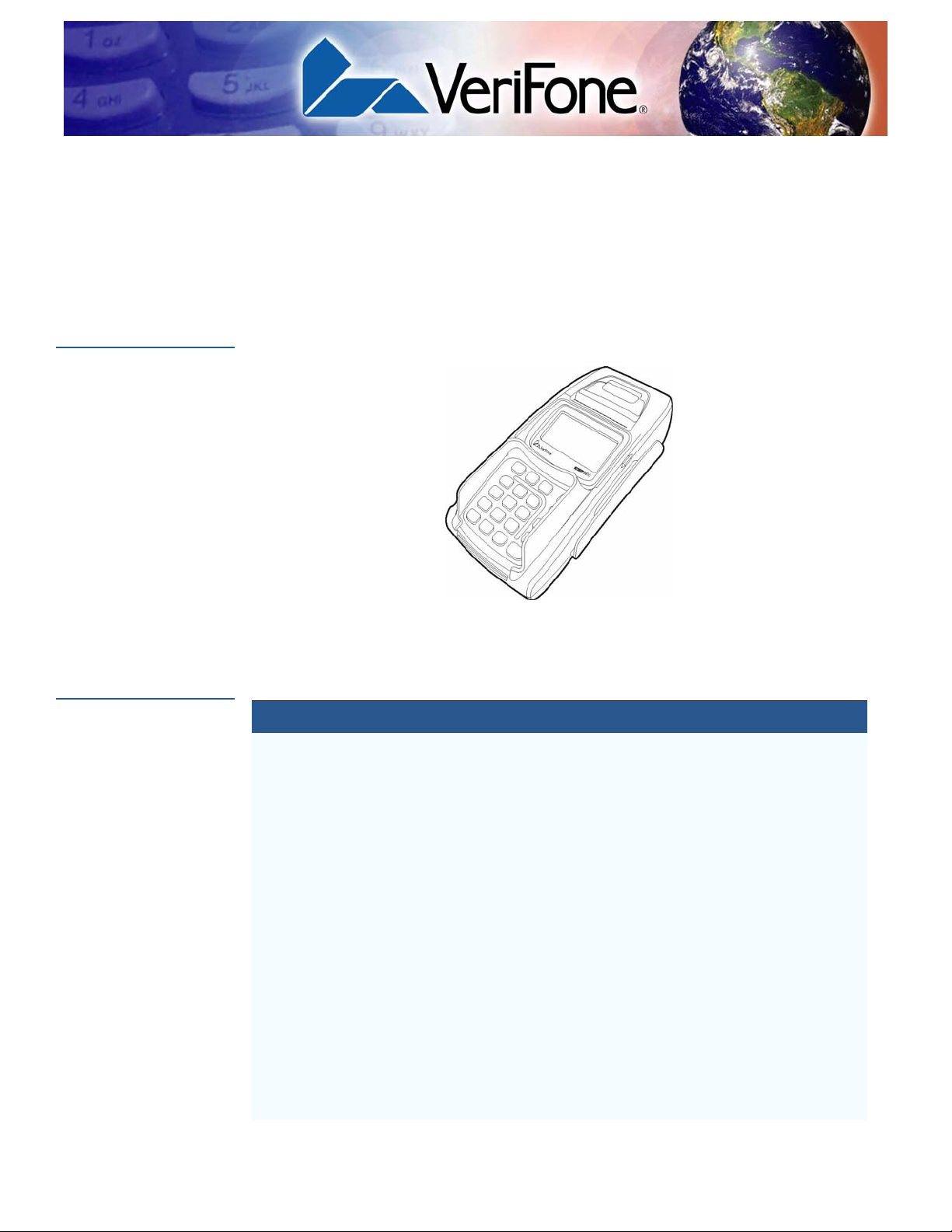
The NURIT 8400 Countertop Payment Terminal is one of the most advanced,
versatile, secure, and convenient POS terminals manufactured today.
Figure 1 The NURIT 8400 Terminal
The following is a list of features of the NURIT 8400:
Table 3 NURIT 8400 Features
Feature Description
LCD Display
• Graphical LCD display
• White LED backlight
Keypad
Smart Card Reader
Magnetic Stripe
Card Reader
SAM-SD Cards
Compartment
• 128 x 64 pixels, 63 x 35 mm
• 20 keys comprised of:
• 10-key telephone-style keypad
• 10 function and special keys
• Integrated, front-entry, EMV-compliant smart card
reader
• Integrated, bi-directional magnetic stripe card reader
• Compartment for up to four SAM cards
• OR, compartment for up to two SAM cards and o ne SD
card
Note: Configuration is model-dependent.
NURIT 8400 INSTALLATION GUIDE 7
Page 8

OVERVIEW
Features at a Glance
Table 3 NURIT 8400 Features
Feature Description
Thermal Printer
Terminal Interface
Connector
Modem
Power
• Integrated printer uses thermal paper
• Easy-load mechanism
• Barrel power (POWER) connector
• Two RS232 ports (COM), with RJ45 connectors*
• Two RJ11 connectors, for telephone (LINE) and
external telephone (
PHONE) connections*
• PIN pad (PIN PAD) port, with an RJ11 connector*
• Ethernet LAN (ETH) port, with an RJ45 connector*
*Note: Configuration is model-dependent.
• Choice of three speeds (model dependent):
• 14.4 Kbps
• 33.6 Kbps
• 56 Kbps and V.92
• Terminal 9 V at 4 A
• AC/DC adapter (safety approved)
Operating System
Input: 100-240 VAC
Output: 9VDC at 4A
• Ported NURIT for maximum application portability
8 NURIT 8400 INSTALLATION GUIDE
Page 9

Setup
CHAPTER 2
This chapter describes the setup procedure for NURIT 8400, in the following
sections:
• Selecting Location
• Unpacking Shipping Carton
• Examining NURIT 8400 Features
• Opening and Closing Compartment Covers
• Installing SAM and SD Cards
• Connecting the Battery Pack
• Using the Printer
• Power Supply
• Connecting Cables
Selecting
Location
Ease of Use
• Using the Magnetic Stripe Card Reader
• Using the Smart Card Reader
• Using the Keypad Privacy Shield
Use the following guidelines to select a location for the NURIT 8400.
• Select a location convenient for both merchant and cardholder.
• Select a flat support surface, such as a countertop or table. Serious damage
may result if device falls.
• Select a location near a power outlet and the terminal, ECR, or computer
connected to the NURIT 8400. For safety, do not place objects on the cables
or cords, or string across a walkway.
• If the NURIT 8400 is to be connected to a telephone line, place it close
enough to the telephone outlet to allow connection.
NURIT 8400 INSTALLATION GUIDE 9
Page 10
SETUP
Selecting Location
Environmental
Factors
CAUTION
• Do not use the unit where there is high heat, dust, humidity, moisture, or
caustic chemicals or oils.
• Do not use the NURIT 8400 in a known blasting area.
• Do not use the NURIT 8400 in an area of potential explosive atmosphere,
such as fuel or chemical storage or transfer facilities, or in any area where you
would be advised to turn off a vehicle’s engine.
• Keep the unit away from direct sunlight and anything that radiates heat, such
as a stove or a motor.
• Do not use the NURIT 8400 outdoors.
• Do not cover slots and openings of the device. They may be provided for
ventilation and protection against overheating. Never place the device near
radiators, or in a place where proper ventilation is not provided.
• Do not cover the terminal.
• Maintain at least 22 cm (8.5 in) of clear space around the terminal in its fixed
operating location, in order to assure good ventilation.
The NURIT 8400 is not waterproof or dustproof, and is intended for indoor use
only. Any damage to the unit from exposure to rain or dust can void any warranty.
CAUTION
WARNING
A keypad privacy shield is pre-installed on all models of the NURIT 8400. F ailing
to install or removing the keypad privacy shield, or failing to instruct the
cardholder to obstruct visual observation of the PIN entry with his/her body and
hand, may render the terminal non-compliant with ISO 9564 for PIN protection
and may violate card association requirements for PIN entry devices.
If for any reason, the keypad privacy shield needs to be replaced, contact a
VeriFone service representative.
For persons using a pacemaker or other medical device, please read the
following important safety notes:
Though most electronic equipment and critical medical devices are shielded
against radio-frequency signals, it is important to realize the possibilities of
potential interference and to know the standard precautions that may be ta ken.
Consult the manufacturer of your medical device to determine its level of
shielding.
10 NURIT 8400 INSTALLATION GUIDE
Page 11

SETUP
Selecting Location
NOTE
Electrical
Considerations
When the NURIT 8400 terminal is used as a secure PIN entry device:
• The customer should be able to obstruct visual observation of the PIN
entry with his/her body and hand.
• The cardholder must be clearly instructed to obstruct visual observat ion of
the PIN entry with his/her body and hand.
Failure to comply with these conditions may render the terminal non-compliant
with ISO 9564 for PIN protection and may violate card association requirements
for PIN entry devices.
• Avoid using this product during electrical storms.
• Avoid locations near electrical appliances or other devices that cause
excessive voltage fluctuations or emit electrical noise (for example, air
conditioners, electric motors, neon signs, high-frequency or magnetic security
devices, or computer equipment).
• Do not use the NURIT 8400 near water or in moist conditions.
• Never spill any liquid on the device.
• Never push objects into the device through slots (other than those spe cifically
intended for the magnetic stripe, smart cards, SAM cards, or cable ports).
WARNING
• To reduce the risk of shock, do not disassemble any of the equipment or
accessories referred to in this manual. If required, take the equipment to a
qualified service representative. Incorrect reassembly or opening or removing
covers may expose you to dangerous voltages or other risks.
Due to risk of shock or damage, do not use the NURIT 8400 near water,
including a bathtub, wash bowl, kitchen sink or laundry tub, in a wet basement, or
near a swimming pool.
NURIT 8400 I
NSTALLATION GUIDE 11
Page 12

SETUP
Unpacking Shipping Carton
Unpacking
Shipping Carton
To unpack the
shipping carton
Open the shipping carton and carefully inspect its conten ts for possible t ampering
or shipping damage. The NURIT 8400 is a secure product and any tampering can
cause it to cease to function or to operate in an unsecured manner.
1 Remove and inspect the contents of the shipping carton. The NURIT 8400
carton includes the following components:
• NURIT 8400 terminal
• Power pack
• Power cord
• Documentation
• Ethernet cable (model dependent)
• Telephone line cable (model dependent)
• Thermal paper
• Battery pack (model dependent)
• Keypad privacy shield (pre-installed)
2 Remove all plastic wrapping from the components.
WARNING
NOTE
3 Remove the clear protective film from the LCD screen.
4 Save the shipping carton and packing material for future repackin g or moving
of the device.
Do not use a unit that has been tampered or damaged.
The NURIT 8400 comes equipped with tamper-evident labels. If a label or
component appears damaged, please notify the shipping company and your
VeriFone service provider immediately.
The package contents, including interconnection cable types, may vary
according to the specific model.
Some or all of the accessories contained in the box may already be installed in
the terminal.
12 NURIT 8400 INSTALLATION GUIDE
Page 13
SETUP
R
Examining NURIT 8400 Features
Examining
NURIT 8400
Features
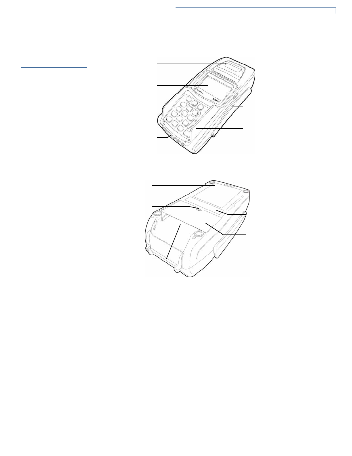
Before you continue with the installation process, familiarize yourself with the
NURIT 8400 features:
PAPER COVER
LCD SCREEN
MAGNETIC STRIPE CARD SLOT
KEYPAD
KEYPAD PRIVACY SHIELD
SMART CARD SLOT
Figure 2 NURIT 8400 Terminal Features (Front Panel)
BATTERY PACK/CARD
COMPARTMENT COVER
RECESS
MODEL/SERIAL NUMBER AND
COMPLIANCE LABEL
CABLE COMPARTMENT COVE
INTERCONNECTION
CABLE GUIDE
Figure 3 NURIT 8400 Terminal Features (Bottom Panel)
NURIT 8400 I
NSTALLATION GUIDE 13
Page 14

SETUP
Examining NURIT 8400 Features
Terminal Front
Panel
Terminal Bottom
Panel
The front panel of the NURIT 8400 terminal (see Figure 2) includes the following
features:
• A terminal display, backlit LCD screen.
• A 20-key, telephone-style keypad.
• A keypad privacy shield.
• A magnetic card reader, built into the top of the terminal. Bi-directional
swiping capabilities. Swipe the card with the magnetic stripe down and left,
towards the terminal and the keypad. For further directions, see Using the
Magnetic Stripe Card Reader.
• A smart card reader, built into the front of the terminal. For further dire ctio ns,
see Using the Smart Card Reader.
• A thermal printer.
The bottom panel of the NURIT 8400 terminal (see Figure 3) includes the
following features:
• An interconnection port panel, with a removable interconnection cable cover.
The interconnection port panel includes the following optional ports (model
dependent):
• A Power Socket where the power cable is plugged. For directions on
connecting the terminal to an electrical outlet, see Power Supply.
• A Telephone Line Port (model dependent). For directions on connecting
to the
LINE port, see Telephone Line Connection.
• An External Telephone Port (model dependent). For directions on
connecting to the
PHONE port, see External Telephone Connection.
• Two RS232 Ports (model dependent). For directions on connecting to the
/COM2 ports, see RS232 Connection.
COM1
• A PIN Pad Port. For directions on connecting to the PIN PAD port, see
External PIN Pad Connection.
For directions on how to install and remove the cable compartment cover, see
Opening and Closing Compartment Covers.
For directions on how to connect and remove cables, see Connecting Cables.
• A battery pack/card compartment with removable cover. The card
compartment is where the optional SAM (security access module) and SD
(secure digital) cards are installed (configuration is model dependent).
For directions on installing and removing the battery pack/card compartment
cover, see Opening and Closing Compartment Covers.
14 NURIT 8400 INSTALLATION GUIDE
For directions on installing and removing the battery pack, see Connecting the
Battery Pack.
Page 15
Opening and Closing Compartment Covers
For directions on installing and removing the SAM and SD cards, see
Installing SAM and SD Cards.
SETUP
NOTE
Opening and
Closing
Compartment
Covers
NOTE
To remove the battery
pack/card
compartment cover
VeriFone ships variants of the NURIT 8400 terminal for different markets. Your
terminal may have a different configuration. The following devices may or may
not be present: a smart card reader, up to four SAM cardholders, an SD
cardholder, or a battery pack. However, the basic processes described in this
guide remain the same, regardless of terminal configuration.
To access the cable compartment and the battery pack/card compartment, you
have to remove their cover.
Battery packs, and SAM and SD card configurations are model dependent.
1 Place the NURIT 8400 face down on a soft, smooth surface, so as not to
damage the LCD screen.
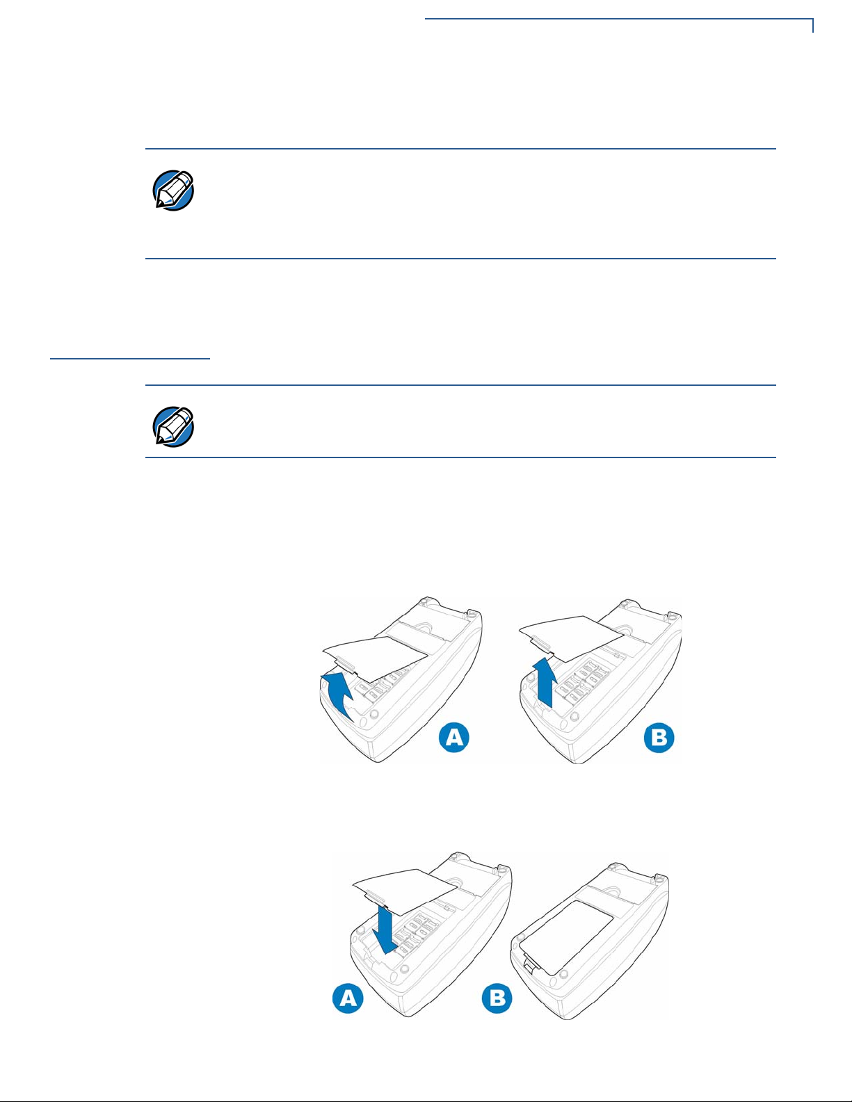
2 Release the battery pack/card compartment cover by pressing and lifting its
locking tab.
To close the battery
pack/card
compartment cover
3 Lift the cover and detach it from the terminal.
Figure 4 Removing the Battery Pack/Card Compartment Cover
1 Place the NURIT 8400 face down on a soft, smooth surface, so as not to
damage the LCD screen.
Figure 5 Closing the Battery Pack/Card Compartment Cover
NURIT 8400 I
NSTALLATION GUIDE 15
Page 16

SETUP
Opening and Closing Compartment Covers
2 Insert the two hinges of the battery pack/card compartment cover into the
3 Close the compartment cover and press down until the lo cking tab snaps into
hinge slots on the edge of the battery pack/card compartment.
place.
To remove the cable
compartment cover
To replace the cable
compartment cover
1 Place the NURIT 8400 face down on a soft, smooth surface, so as not to
damage the LCD screen.
2 Release the cable compartment cover by placing a finger in the comp artment
recess.
3 Squeeze and lift the cover, detaching it from the terminal.
Figure 6 Removing the Cable Compartment Cover
1 Place the NURIT 8400 face down on a soft, smooth surface, so as not to
damage the LCD screen.
2 In one hand, gather the cables together.
3 With the other hand, insert the two tabs at the back of the cable compartment
cover, on an angle into the tab grooves on the terminal.
4 Lower the cable compartment cover, with the gathered cables under the
5 Close the compartment cover, pushing down until the tabs snap into place.
Figure 7 Closing the Cable Compartment Cover
16 NURIT 8400 INSTALLATION GUIDE
interconnection cable guide.
Page 17

SETUP
Installing SAM and SD Cards
Installing SAM
and SD Cards
To install a SAM card
Configuration of SAM and SD cards are model dependent. You can install up to
four SAM cards or an SD card with up to two SAM cards in the NURIT 8400
terminal, depending on the particular model.
Depending on your model of the NURIT 8400 terminal, the card compartment may
be shared with a battery pack. To gain access to the battery pack/card
compartment, you must first remove the battery pack/card compartment cover.
For information on removing and replacing the battery pack/card compartment
cover, see Opening and Closing Compartment Covers.
1 Remove the battery pack/card compartment cover. See Figure 4.
2 If necessary, remove the battery pack. See Figure 12.
3 Slide the locking-clasp in the direction indicated by the engraved arrow to the
OPEN position.
4 Lift the cardholder on its hinge to a vertical position.
5 Hold the SAM card vertically, with the beveled corner at the top edge and the
metallic contacts facing towards the contacts on the reader.
6 Slide the card into the cardholder.
NOTE
CAUTION
Figure 8 Opening a Cardholder and Installing a SAM Card
Make sure that you first slide the end closest to the chip on the card into the
grooves of the holder and that the beveled corner is on the top edge of the SAM
card.
7 Lower the SAM cardholder onto its base. Check that the corner of the SAM
card is not obstructed by the triangular protrusion at the corner of the
cardholder base.
8 Lock the SAM cardholder by sliding the cardholder locking clasp to the LOCK
position.
Do not bend or scratch the contacts of the SAM cardholder when installing or
removing cards.
NURIT 8400 I
NSTALLATION GUIDE 17
Page 18

SETUP
Installing SAM and SD Cards
9 If necessary, replace the battery pack. See Figure 11.
10 Close the battery compartment cover. See Figure 4.
To remove a SAM
card
To install an SD card
1 Open the card holder, by following steps 1-4 of To install a SAM card and
remove the card.
2 Close the card holder by following steps 7-8 of To install a SAM card.
1 Remove the battery pack/card compartment cover. See Figure 4.
2 If necessary, remove the battery pack. See Figure 12.
3 Hold the SD card directly above the SD card slot, with the metal contacts
facing down and the narrow edge with the beveled corner pointing towards
the slot opening.
4 Lower the SD card into position.
5 Press down on the SD card while sliding it into the slot, until the card snaps
into place.
Figure 9 Inserting the SD Card
6 If necessary, replace the battery pack. See Figure 11.
7 Close the battery compartment cover. See Figure 4.
18 NURIT 8400 INSTALLATION GUIDE
Page 19

SETUP
Installing SAM and SD Cards
To remove an SD
Card
1 Remove the battery pack/card compartment cover. See Figure 4.
2 If necessary, remove the battery pack. See Figure 12.
3 With one hand press down on the SD locking tab, while sliding the card out
with your other hand.
4 Remove the SD card.
Figure 10 Removing the SD Card
5 If necessary, replace the battery pack. See Figure 11.
6 Close the battery compartment cover. See Figure 4.
NURIT 8400 I
NSTALLATION GUIDE 19
Page 20

SETUP
Connecting the Battery Pack
Connecting the
Battery Pack
WARNING
Connecting and
Removing the
Battery Pack
CAUTION
Some models of the NURIT 8400 come with a battery pack. If your model comes
with a battery pack, read this section to know how to install and remove the pack.
Only use battery packs provided by VeriFone. For information about purchasing
additional or replacement batteries, see Accessories and Documentation.
Depending on your model of the NURIT 8400 terminal, the battery pack
compartment may be shared with the SAM and SD cards. To gain access to the
battery pack/card compartment, you must first remove the battery pack/card
compartment cover. For information on removing and replacing the battery pack/
card compartment cover, see Opening and Closing Compartment Covers.
Some models of the NURIT 8400 allow you to operate the terminal without an
external power supply, by using a battery pack.
Make sure to disconnect the DC power supply cord from the terminal before
connecting or removing the battery pack.
To connect the
battery pack
1 Disconnect the DC power supply cord from the terminal.
2 Remove the battery compartment cover. See Figure 4.
3 Turn the battery so that the connecting wires are at the top right hand corner.
4 Insert the battery pack pin connector into the 2-pin port in the battery pack
compartment. The straight side should be facing outwards, while the rounded
edges should be facing inwards, towards the compartment.
5 Insert the battery pack into the battery compartment.
6 Push the connecting wires gently into the cable guide.
Figure 11 Connecting the Battery Pack
7 Close the battery compartment cover. See Figure 5.
8 Connect the DC power supply to the terminal (see Figure 17) or power on the
20 NURIT 8400 INSTALLATION GUIDE
terminal (see Powering On and Off the Terminal With a Battery Pack).
Page 21

SETUP
Connecting the Battery Pack
To disconnect the
battery pack
1 Disconnect the DC power supply cord from the terminal or power off the
terminal. See Powering On and Off the Terminal With a Battery Pack.
2 Remove the battery compartment cover. See Figure 4.
3 Remove the connecting wires from the cable guide.
4 Remove the pin connector, connecting the terminal and the battery pack.
5 Remove the battery pack.
Figure 12 Disconnecting the Battery Pack
6 Close the battery compartment cover. See Figure 4.
Battery Maintenance
CAUTION
7 Connect the DC power supply to the terminal. See Figure 17.
Take care when installing the battery pack. If it is installed incorrectly, it may
explode. Use only a VeriFone supplied battery.
• The supplied high-performance NiMH battery pack provides 7.2 V at
2000 mAh capacity.
• Before using the battery for the first time it is recommended to charge the
battery for 24 hours.
• When fully discharged, the battery pack fully recharges within eight hours
while installed in the terminal. When replacing a battery pack (or using a new
one), the capacity level is not relevant until the battery p ack has complete d an
initial eight hours of charging.
• The terminal can be connected to an AC/DC power supply indefinitely without
causing damage to the battery pack.
• In typical use, the life span of the battery pack exceeds 500 charge cycles,
after which, operating time decreases slowly.
• The battery pack has a self-discharge rate. It loses approximately 1% of its
charge per day when not in use. Replace the battery pack when the charge
capacity is too weak for normal operation.
NURIT 8400 I
NSTALLATION GUIDE 21
Page 22

SETUP
Connecting the Battery Pack
WARNING
• Remove the battery pack from the terminal if you do not intend to use your
NURIT 8400 for an extended period of time.
Do not break open, or separate the battery pack.
WARNING
NOTE
Powering On and
Off the Terminal
With a Battery Pack
NOTE
NOTE
Do not dispose of the NURIT 8400 battery pack NiMh in a fire. NiMh batteries
must be recycled or disposed of properly. Do not dispose of NiMh batteries in
municipal waste sites.
Extreme temperatures degrade the battery pack performance.
Battery Environmental Requirements:
• Standard Charge: 0°C to 45°C (32°F to 113°F)
• Discharge: -20°C to 50°C (-4°F to 122°F)
• Storage: - 20°C to 35°C (-4°F to 95°F)
To power on a terminal, while using a battery pack, press the bottom lef t button on
the keypad. Hold down the button until the terminal powers up.
When the terminal is running on AC power supply, the unit cannot be turned off.
If you keep holding down on the button after the terminal powers up, the terminal
will turn back off.
To power off a terminal, while using a battery pack, press the bottom left button on
the keypad. Hold down the button until the terminal powers down.
22 NURIT 8400 INSTALLATION GUIDE
Page 23

SETUP
Using the Printer
Using the Printer
CAUTION
Loading Paper into
the Printer
To load paper into the
printer
An integrated thermal printer is built into the NURIT 8400. Before you can process
transactions in the NURIT 8400 that require a receipt or record, you must install
paper in the printer.
Do not use labeling paper, manifold paper, and thermal paper of more than
75 µm. If any paper other than that specified is used, high print quality and long
life of the thermal head cannot be guaranteed.
Before using the printer, load a roll of paper into the printer.
1 Place the terminal on a flat, stable surface.
2 Insert two fingers into the recess on the paper compartment cover, beneath
the release latch.
3 Pull the opening latch up until the cover unlocks.
RELEASE LATCH
Figure 13 Opening the Paper Compartment
1 Remove the tape strip from a new paper roll.
2 Unroll approximately 5 cm (2 in) of paper to facilitate the loading process.
3 Hold the paper roll with the unrolled end on the underside.
4 Lower the paper roll into the paper compartment.
Figure 14 Inserting a Paper Roll
NURIT 8400 I
NSTALLATION GUIDE 23
Page 24

SETUP
Using the Printer
5 Pull the unrolled end of the paper approximately 2.5 cm (1 in) out of the p aper
compartment, ensuring that the paper feeds from the underside of the roll.
6 Make sure that the opening latch is down, in its original position.
7 Close the paper compartment cover, pressing down firmly, until it snaps into
place.
Figure 15 Closing the Paper Compartment
Removing the Paper
Roll From the
Printer
To remove a roll of
thermal paper from
the printer
When a roll of paper is finished, or if the paper is jammed, you may have to
remove the old roll in order to replace it.
1 Place the terminal on a flat, stable surface.
2 Insert two fingers into the recess on the paper compartment cover, beneath
the release latch.
3 Pull the opening latch up until the cover unlocks.
4 Lift the paper compartment cover until it is fully open (see Figure 13).
5 Lift the paper roll out of the paper compartment.
Figure 16 Removing the Paper Roll
24 NURIT 8400 INSTALLATION GUIDE
Page 25

SETUP
Power Supply
Power Supply
WARNING
WARNING
NOTE
To connect to the
power supply
Before connecting a power supply, disconnect the power pack cord from the
power outlet.
Connect and route all cables between the NURIT 8400, ECR, and PC before
plugging the power pack cord into a wall outlet or surge protector.
Use only the V eriFone supplied AC/DC power adapter to power the NURIT 8400.
The power adapter provides electrical power to the NURIT 8400 as follows:
• Input (AC):100-240 VAC, 50/60 Hz
• Output (DC): 9 VDC at 4 A
Do not plug the power pack into an outdoor outlet or operate the NURIT 8400
outdoors. Also, disconnecting power during a transaction can cause transaction
data files not yet stored in memory to be lost.
To protect against possible damage caused by lightning strikes and electrical
surges, VeriFone recommends installing a power surge protector.
1 Remove the cable compartment cover. See Figure 6.
2 Connect the power adapter barrel plug into the POWER port on the back of the
terminal.
CAUTION
3 Press the power adapter cable into the cable ditch.
4 Replace the cable compartment cover. See Figure 7.
5 Insert the plug at the other end, into an electrical power outlet.
Figure 17 Power Supply Connection
Make sure that the power cable goes through the cable ditch, in order to prevent
terminal disconnection during handling.
NURIT 8400 I
NSTALLATION GUIDE 25
Page 26

SETUP
Connecting Cables
Connecting
Cables
NOTE
NOTE
The NURIT 8400 has the following model-dependent ports to facilitate different
types of cabling connections:
• Telephone Line Connection
• External Telephone Connection
• Ethernet Connection
• External PIN Pad Connection
• RS232 Connection
You can connect peripheral devices to the NURIT 8400. Consult with your
VeriFone service provider for information about the peripheral devices that you
can connect to your specific model.
• The LINE, PHONE, and ETH are all model dependent connection ports.
• Peripheral devices may require special adapter cables for their connection to the
NURIT 8400. In addition, certain peripher al devices require an external power supply.
• Refer to the product documentation of the specific peripheral devices, or contact your
local VeriFone representative or service provider for further details.
Figure 18 NURIT 8400 Connections
NOTE
Figure 18 is for illustration purposes only. T erminal connection configurations are
model dependent. Always check the connection label, to know which port you are
using.
CAUTION
26 NURIT 8400 INSTALLATION GUIDE
• Turn off the POS terminal, and any peripheral devices whenever you connect or
disconnect the NURIT 8400.
• Do not disconnect the NURIT 8400 from an external device when it is processing dat a.
Page 27

Connecting Cables
To connect cables 1 Turn off the external device to which the terminal is to be connected and/or
disconnect the AC/DC power adapter form the AC electrical power outlet.
2 Remove the cable compartment cover. See Figure 6.
3 Insert the plug into the appropriate connector on the terminal connections
panel.
4 Replace the cable compartment cover. See Figure 7.
5 Insert the plug at the other end, into the external device.
6 Turn on the external device and/or reconnect the AC/DC power adapter to
the AC electrical power outlet.
SETUP
Telephone Line
Connection
WARNING
CAUTION
NOTE
NOTE
The modem version of the NURIT 8400 must be connected to a telephone line in
order to dial-up. You may connect an external telephone to the terminal, so you
still have telephone access while using the unit. To connect an external telephone,
see External Telephone Connection.
When in the vicinity of a gas leak, do not use the NURIT 8400, a standalone
telephone, or a telephone connected to the terminal to report the leak.
Only use the assigned connection port, labeled LINE for telephone line
connections.
It is recommended that you use a dedicated telephone line with the NURIT 8400.
In some models the external telephone is disabled during transactions.
Cancel the call waiting service for the telephone line to which the NURIT 8400 is
connected. Contact your telephone company for information.
NURIT 8400 I
NSTALLATION GUIDE 27
Page 28

SETUP
Connecting Cables
Connect one end of the RJ11 cable to the LINE socket at the back of the
NURIT 8400 and the other end to a standard RJ11 type modular telephone line
outlet.
Figure 19 NURIT 8400 Telephone Line Connection
NOTE
Use only the telephone cord shipped with the terminal. Using a different
telephone cord may cause the terminal to malfunction.
Telephone Outlet Types
The following types of telephone outlets are common:
• Modular
This is the most common type of telephone outlet used. Plug the supplied
telephone cord from the terminal into a standard modular telephone
connector. If you do not have a modular connector, contact your local
telephone company or a qualified telephone technician.
• 4-Prong Connector
You must purchase a special adapter for use with a 4-prong connector. This
adapter plugs into a 4-prong connector and the telephone line cord plugs into
the adapter.
• Hard-wired
You must purchase a special modular connector adapter for this direct-type
hard-wire connection that replaces older connecting blocks. Contact your local
telephone company or a qualified telephone technician for correct information
on color-coded connections.
28 NURIT 8400 INSTALLATION GUIDE
Page 29

SETUP
Connecting Cables
External Telephone
Connection
WARNING
NOTE
NOTE
You may connect a standard external telephone to a model of the NURIT 8400
that uses the analog telephone network for communications, so you still have
telephone access while the modem is connected to the telephone line.
When in the vicinity of a gas leak, do not use the NURIT 8400, a standalone
telephone, or a telephone connected to the terminal to report the leak.
When connecting an external telephone to the terminal, follow these precautions
to ensure proper completion of transactions:
• Cancel the call waiting service for the telephone line to which the
NURIT 8400 is connected. Contact your telephone company for
information.
• Do not initiate a telephone call, send a fax, or lift the handset when the
NURIT 8400 is processing a transaction.
If you want to connect an external telephone to the NURIT 8400 terminal along
with an analog telephone network connection, you must use a 2-socket RJ11
plug in the modular wall connector.
Ethernet
Connection
To connect the
NURIT 8400 to an
Ethernet LAN
Connect one end of the RJ11 cable to the
PHONE socket at the back of the
NURIT 8400 and the other end to the RJ11 connector on the telephone or fax
machine.
Figure 20 NURIT 8400 External Telephone connection
Some models of the NURIT 8400 can be connected to a 10BaseT Ethernet Local
Area Network (LAN).
Connect one end of the Ethernet adapter cable to the
ETH port on the back of the
terminal and the other into its corresponding socket.
Figure 21 NURIT 8400 Ethernet Connection
NURIT 8400 I
NSTALLATION GUIDE 29
Page 30

SETUP
Connecting Cables
External PIN Pad
Connection
CAUTION
NOTE
The NURIT 8400 can connect to an external PIN pad.
You may use the following ports for a PIN pad connection (connections are
model dependent):
• PIN P AD
• COM1
• COM2 (Only with external power supply for PIN pad. See RS232 Connection)
Connect one end of the connector cable (supplied with the termin al) to the
(See RS232 Connection)
PIN PAD
port on the back of the terminal and the other into its corresponding socket.
The COM1 and PIN PAD port both provide a power supply for peripheral devices.
Both currents are able to supply a sum of up to 500 mA, in total. (Both currents
should total under 500 mA.)
The power supply in the
COM1 and PIN PAD is 6 VDC (minimum) to 9 VDC
(maximum).
.
Figure 22 NURIT 8400 PIN Pad Connection
30 NURIT 8400 INSTALLATION GUIDE
Page 31

SETUP
Connecting Cables
RS232 Connection
NOTE
NOTE
Both RS232 ports (COM1 and COM2) can be used to connect the NURIT 8400 to
another related device, such as a PC. Connect one end of the RS232 cable to
either the
COM1 or COM2 socket at the back of the terminal and the other end to the
desired related device, such as the PC.
The RS232 cable is not included with the NURIT 8400. A standard RS232 cable
may be used with the unit.
The COM1 and PIN PAD port both provide a power supply for peripheral devices.
Both currents are able to supply a sum of up to 500 mA, in total. (Both currents
should total under 500 mA.)
The power supply in the
COM1 and PIN PAD is 6 VDC (minimum) to 9 VDC
(maximum).
COM2 port does not provide power under any configuration.
The
Figure 23 Possible NURIT 8400—RS232 Connections
NURIT 8400 I
NSTALLATION GUIDE 31
Page 32

SETUP
Using the Magnetic Stripe Card Reader
Using the
Magnetic Stripe
Card Reader
To use the magnetic
stripe card reader
The magnetic stripe card reader is located at the top end of the NURIT 8400
terminal. Use the magnetic stripe card reader with a magnetic stripe card.
1 Hold the card with the magnetic stripe positioned down and facing left.
2 Insert the card into the top end of the card reader slot located on the right
side of the terminal.
3 Swipe the card in a smooth, continuous movement, all the way through the
slot.
NOTE
Figure 24 Swiping Magnetic Card
For guidance, a pictogram near the card slot indicates how to swipe t he magnetic
stripe card in the card reader.
It is recommended that you swipe the card from top to bottom, though the
magnetic stripe card reader supports bi-directional swiping of cards.
32 NURIT 8400 INSTALLATION GUIDE
Page 33

SETUP
Using the Smart Card Reader
Using the Smart
Card Reader
To use the smart card
reader
The EMV-comp atible smart card reader is located at the bottom end of the NURIT
8400 terminal. Use the smart card reader with a smart card.
1 Hold the smart card horizontally , with the met al chip facing up and at the edge
of the card nearest to the smart card reader slot.
2 Insert the card all the way into the smart card reader slot, until it snaps in.
Figure 25 Inserting Smart Card
3 Remove the card when prompted by the POS terminal, depending on the
specific application being used.
NOTE
For guidance, a pictogram near the card slot indicates how to insert the smart
card into the smart card reader. In addition, insertion direction arrows may be
engraved or inscribed on the smart card.
NURIT 8400 I
NSTALLATION GUIDE 33
Page 34

SETUP
Using the Keypad Privacy Shield
Using the
Keypad Privacy
Shield
WARNING
NOTE
To install the keypad
privacy shield
The keypad privacy shield is included with models of the NURIT 8400 that are
designed for secure PIN entry. The privacy shield may already come installed on
the terminal.
Failing to install or removing the keypad privacy shield, or failing to instruct the
cardholder to obstruct visual observation of the PIN entry with his/her body and
hand, may render the terminal non-compliant with ISO 9564 for PIN protection
and may violate card association requirements for PIN entry devices.
In addition to the installation of the keypad privacy shield, the cardholder must be
clearly instructed to obstruct visual observation of the PIN entry with his/her body
and hand. (See Environmental Factors.)
1 Place the terminal on a flat, stable surface, or hold it securely in one hand.
2 Hold the keypad privacy shield above the terminal.
3 Tilt one side of the keypad privacy shield downward at an angle of
approximately 30°.
4 Insert the curved tab on the back side of the keypad privacy shield into the
circular opening positioned on either side of the terminal (on either side of the
top of the keypad area).
Figure 26 Installing the Keypad Privacy Shield
5 Push down on the same side’s front of the keypad privacy shield, until the
6 Position the second tab, at the front of the terminal, into the tab slot.
7 Push down on the remaining corner of the keypad privacy shield, until it
To remove the keypad
privacy shield
1 Place the terminal on a flat, stable surface, or hold it securely in one hand.
2 Grasp either side of the keypad privacy shield.
3 Squeeze and pull on a diagonal one of the back side tabs of the privacy
4 Pull the keypad privacy shield away from the terminal.
34 NURIT 8400 INSTALLATION GUIDE
front tab snaps into place.
snaps into place.
shield, until the back side tab releases.
Page 35

Specifications
CHAPTER 3
This chapter discusses power requirements, dimensions, and other specifications
of the NURIT 8400.
Specifications
Model
Power Pack
Printer
Modem
Physical
The following specifications describe the NURIT 8400 physical and electrical
characteristics.
NURIT 8400
Terminal 9 V at 4 A.
AC/DC adapter (safety approved)
Input: AC 100-240 VAC, 50/60 Hz
Output: DC 9 VDC at 4 A
Only use the power supply provided by VeriFone.
Thermal; easy-load mechanism.
Choice of three speeds: 14.4 Kbps, 33.6 Kbps, or 56 Kbps and V.92 dial-up
modem (model dependent).
Length: 232.5 mm (9.15 in.). Width: 109.9 mm (4.32 in.). Height: 78.5 mm
(3.09 in.). Weight: terminal, 310 g (10.93 oz.); full shipping, 759 g (26.77 oz.).
NURIT 8400 INSTALLATION GUIDE 35
Page 36

SPECIFICATIONS
Environmental, Regulatory, and Perf ormance Specifications
Environmental,
Regulatory, and
Performance
Specifications
Temperature and
Humidity
The NURIT 8400 meets all the necessary environmental, regulatory, and
performance standards for its intended use and expected market. VeriFone
recognizes its responsibility to minimize the environmental impacts of its
operations and products. For more information on the NURIT 8400 terminal
certification and regulatory details, refer to the NURIT 8400 Certifications and
Regulations (VPN DOC108EN03-A).
This device is not intended for outdoor use and is certified for indoor use only.
Operating Temperature and Humidity
• Temperature: 0
o
C to +50oC (+32oF to +122oF)
• Humidity: 40% RH, non-condensing
Storage Temperature and Humidity
• Temperature: -20
o
C to +70oC (-4oF to +158oF)
• Humidity: 30% RH, non-condensing
36 NURIT 8400 INSTALLATION GUIDE
Page 37

Maintenance and Cleaning
The NURIT 8400 has no user-serviceable parts.
CHAPTER 4
CAUTION
Cleaning the
NURIT 8400
To clean the
NURIT 8400
• Opening or disassembling the terminal in any way automatically erase all
secret encryption keys and will render the terminal inoperable.
• Opening the terminal will void any warranty and security certification. It may
also result in irreversible damage to the unit’s electronic circuitry.
In order to maintain the NURIT 8400 in proper working condition:
• Keep the terminal dry and in the cleanest possible working and storage
environment.
• Do not store the terminal in extremely hot or cold areas.
• Do not shake or drop the terminal.
Disconnect the device from the power supply and any peripherals before cleaning.
• Gently wipe off dirt from the body of the terminal with a soft, damp, lint-free
cloth. A very mild dishwashing detergent can be used to dampen the cloth.
• If available, a low-pressured blower can be used to remove dirt accumulated
around the keypad buttons.
• Use a soft cloth, an eyeglass lens wiper, or a lens blower to remove dust and
dirt from the LCD screen.
NURIT 8400 INSTALLATION GUIDE 37
Page 38

MAINTENANCE AND CLEANING
Cleaning the NURIT 8400
• To clean the keypad, use a soft, damp, lint-free cloth slightly dampened with
water and a drop or two of mild soap. For stubborn stains, use alcohol or an
alcohol-based cleaner. For best results, use a Ve riFone Cleaning Kit (refer to
the Accessories and Documentation section).
CAUTION
Never use abrasive compounds or solvents, thinner, trichloroethylene, ketonebased solvents, benzene, or synthetic cleansers– they can deteriorate plastic or
rubber parts.
Do not spray cleaners or other solutions directly onto the keypad or display.
Never clean the unit with liquids. Use only a lightly dampened cloth or soft brush.
Never rub or strongly press on the LCD display.
Do not use liquid or aerosol cleaners. Use a damp cloth for cleaning and/or a soft
brush.
38 NURIT 8400 INSTALLATION GUIDE
Page 39

CHAPTER 5
Troubleshooting
NOTE
CAUTION
Guidelines
The troubleshooting guidelines provided in the following section are included to
assist you to successfully install and configure your NURIT 8400 device. If you
have problems operating your NURIT 8400 device, please read through these
troubleshooting examples.
If the problem persists even after performing the outlined guidelines or if the
problem is not described below, contact your local VeriFone representative for
assistance. Typical examples of malfunction you may encounter while operating
your NURIT 8400 device and steps you can take to resolve them are listed.
The NURIT 8400 comes equipped with tamper-evident labels. The device
contains no user serviceable parts. Do not, under any circumstance, attempt to
disassemble the device. Perform only those adjustments or repairs specified in
this guide. For all other services, contact your local VeriFone service provider.
Service conducted by parties other than authorized VeriFone representatives
may void warranty.
Use only a VeriFone-supplied power pack. Using an incorrectly rated power
supply may damage the device or cause it not to work as specified. Before
troubleshooting, ensure that the power supply matches the requirements
specified at the bottom of the device. (See Chapter 3, Specifications for detailed
power supply specifications.) Obtain the appropriately rated power supply before
continuing with troubleshooting.
Terminal Has No
Power
If the NURIT 8400 appears to have no power:
• Check all cable connections.
• Check that the terminal is correctly connected to the power supply, as
described in Power Supply.
• Try adjusting the LCD screen contrast settings, using the designated, model-
dependent, key combination.
• Remove all accessories, external cables, and connections, except for the
power supply and try to operate the terminal.
• If the problem persists, contact your VeriFone distributor or service provider.
NURIT 8400 INSTALLATION GUIDE 39
Page 40

TROUBLESHOOTING GUIDELINES
Transactions Cannot be Completed Successfully
Transactions
Cannot be
Completed
Successfully
Printer Does Not
Print
If transactions cannot be completed successfully:
• Try to perform the transaction using a different magnetic stripe card or smart
card (model dependent).
• Make sure that all terminal cables are properly connected. (See Connecting
Cables).
• Make sure that you insert or swipe the card in the proper manner.
• Attempt to complete several transactions manually using the terminal’s
keypad instead of using customer cards. If all these transactions are
completed successfully, contact an authorized representative or service
provider.
• If the problem persists, contact your VeriFone distributor or service provider.
If the printer does not work properly:
• Check the power connection.
• Check that the printer has paper and that the paper is properly installed. Take
out and then reinsert the paper, if necessary. (See Loading Paper into the
Printer).
Magnetic Stripe
Card Reader
Does Not
Function
Properly
Smart Card
Reader Does Not
Function
Properly
• Try to load a new roll of p aper into the printer. Make sure that you are using an
approved paper type. (See Loading Paper into the Printer).
• Run the system mode printer diagnostic.
• If the problem persists, contact your VeriFone distributor or service provider.
If the magnetic stripe card reader does not function properly:
• Check that the card has been swiped with its magnetic stripe facing left and at
the lower edge of the card, as described in Using the Magnetic Stripe Card
Reader.
• Swipe the magnetic stripe card in the opposite direction.
• If possible, try using a different magnetic card.
• If the problem persists, contact your VeriFone distributor or service provider.
If the smart card reader does not function properly:
• Check that the smart card is fully inserted with the metal chip facing up and at
the edge of the card nearest to the smart card reader slot, as described in
Smart Card Reader Does Not Function Properly.
• If possible, try using a different smart card.
• If the problem persists, contact your VeriFone distributor or service provider.
The Keypad
Does Not
If the keypad does not respond:
• Refer to user documentation for the particular application in use.
Respond
• If the problem persists, contact your VeriFone distributor or service provider.
40 NURIT 8400 INSTALLATION GUIDE
Page 41

TROUBLESHOOTING GUIDELINES
An Incorrect Response or Data Is Obtained
An Incorrect
Response or
Data Is Obtained
“Tampered
Device”
Displayed On
Screen and
Keypad
Inoperable
If an incorrect response or data is obtained:
• Refer to user documentation for the particular application in use.
• If the problem persists, contact your VeriFone distributor or service provider.
If “Tampered Device” is displayed on the screen and/or the keypad is inoperable
contact an authorized service representative.
NURIT 8400 I
NSTALLATION GUIDE 41
Page 42

TROUBLESHOOTING GUIDELINES
“Tampered Device” Displayed On Screen and Keypad Inoperable
42 NURIT 8400 INSTALLATION GUIDE
Page 43

Service and Support
For NURIT 8400 problems, contact your local VeriFone representative or service
provider.
For NURIT 8400 product service and repair information:
• USA – VeriFone Service and Support Group, 1-800-834-4366,
Monday - Friday, 8 A.M. - 8 P.M., eastern time.
• International – Contact your VeriFone representative.
CHAPTER 6
Service Returns
NOTE
Before returning the NURIT 8400 to VeriFone, you must obtain a Merchandise
Return Authorization (MRA) number. The following procedure describes how to
return one or more NURIT 8400 for repair or replacement (U.S. customers only).
International customers, please contact your local VeriFone representative for
assistance with your service, return, or replacement.
1 Gather the Product ID printed labels (see Figure 27) on the bottom of each
NURIT 8400 to be returned.
2 Within the United States, call VeriFone toll-free at 1-800-834-4366.
3 Select the MRA option from the automated message. The MRA department
is open Monday–Friday, 8 A.M.–8 P.M., eastern time.
4 Give the MRA representative the information gathered in Step 1.
If the list of serial numbers is long, you can fax the list, along with the
information gathered in Step 1, to the MRA department at 1-727-953-4172
(U.S.).
• Please address the fax clearly to the attention of the “VeriFone MRA
Dept.”
NOTE
• Include a telephone number where you can be reached and your fax
number.
• You will be issued MRA number(s) and the fax will be returned to you.
One MRA number must be issued for each NURIT 8400 you return to VeriFone,
even if you are returning several of the same model.
NURIT 8400 INSTALLATION GUIDE 43
Page 44

SERVICE AND SUPPORT
Service Returns
5 Describe the problem(s) and provide the shipping address where the
repaired or replacement unit must be returned.
6 Keep a record of the following items:
• Assigned MRA number(s).
• VeriFone serial number assigned to the NURIT 8400 you are returning for
service or repair (serial numbers are located on the bottom of the unit (see
Figure 27).
• Shipping documentation, such as air bill numbers used to trace the
shipment.
• Model(s) returned (model number is a part of the Product ID and is located
on the VeriFone label on the bottom of the NURIT 8400).
MODEL/ SERIAL NUMBER
Figure 27 Information Label on Unit Bottom
44 NURIT 8400 INSTALLATION GUIDE
Page 45

SERVICE AND SUPPORT
Accessories and Documentation
Accessories and
Documentation
Power Supply
Battery Pack
VeriFone Cleaning
Kit
VeriFone produces accessories and documentation for the NURIT 8400. When
ordering, please refer to the part number in the left column.
VeriFone Online Store at www.store.verifone.com
• USA – VeriFone Customer Development Center, 1-800-834-4366,
Monday - Friday, 7 A.M. - 8 P.M., eastern time
• International – Contact your VeriFone representative
TRF10800 DC power pack (universal)
WIR30017 AC power cord (United States of America)
Various others, by country: contact your local VeriFone representative or service
provider to identify the best power cord for your needs.
BAT10800
02746-01
Documentation
To learn more about NURIT 8400, refer to the following set of documents:
NURIT 8400 Quick Installation Guide
NURIT 8400 Certifications and Regulations VPN DOC108EN03-A
VPN DOC108EN02-A
NURIT 8400 I
NSTALLATION GUIDE 45
Page 46

SERVICE AND SUPPORT
Accessories and Documentation
46 NURIT 8400 INSTALLATION GUIDE
Page 47

INDEX
A
accessories 45
data cables 45
documentation 45
power pack 45
power supply 45
B
bottom panel
terminal
14
C
cables
connecting
ordering data cables 45
COM connections 31
connections
cables
COM 31
ethernet 29
external telephone 29
LINE 27
PHONE 29
PIN pad 30
power supply 25
RS232 31
telephone line 27
27
26
connections
external telephone connection 29
29
F
features
front panel
front panel
features
14
14
I
installation
SAM cards
SD card 17
terminal location 9
unpack the shipping carton 12
17
L
LCD
troubleshooting
LINE connections 27
39
M
magnetic stripe card reader
troubleshooting
using 32
maintenance
cleaning
returning a unit for repair or replacement 43
37
40
D
data cables, ordering 45
display
troubleshooting
documentation 45
accessories 45
acronym definitions 6
conventions 5
related 5
39
E
electrical considerations 11
ethernet
P
paper
inserting
PHONE connections 29
PIN pad
connections
power
troubleshooting
power pack
AC version
accessories 45
connecting 25
23
30
39
45
NURIT 8400 INSTALLATION GUIDE 47
Page 48

INDEX
R
DC version 45
ordering 45
power supply 25
accessories 45
connection 39
printer
paper
inserting
troubleshooting 40
using 23
23
R
repair 43
replacement 43
RS232 connections 31
S
SAM card
installation
SD card
installation
service
returning a unit
smart card reader
troubleshooting
using 33
specifications
environmental,regulatory, and performance
modem 35
physical 35
power pack 35
printer 35
product
display technology
model 35
operating system 35
temperature and humidity 36
17
17
43
40
35
36
electrical considerations 11
environmental factors 10
features 13
general 7, 13
front panel 14
repair 39, 43
replacement 43
service and support 43
troubleshooting 39
transactions
troubleshooting
troubleshooting
blank display
display 39
LCD 39
magnetic stripe card reader 40
power 39
printer 40
smart card reader 40
transactions 40
40
40
T
telephone line connection 27
Temperature 36
terminal
accessories
bottom panel 14
cleaning 37
documentation 45
48 NURIT 8400 INSTALLATION GUIDE
45
Page 49

INDEX
T
NURIT 8400 I
NSTALLATION GUIDE 49
Page 50

VeriFone, Inc.
2099 Gateway Place, Suite 600
San Jose, CA, 95110 USA
Tel: (800) VeriFone (837-4366)
www.verifone.com
NURIT 8400
Installation Guide
VeriFone Part Number DOC108EN04-A, Revision A
 Loading...