

Page 1
DRAFT
MX 900 Series
Inst all at ion Guide
Page 2

DRAFT
Page 3

DRAFT
MX 900 Series Installation Guide
Part Number SPC132-022-01-A, Revision A
March 1, 2012
Ve r iFon e®, Inc.
2099 Gat eway Place
Suit e 600
San Jose, CA 95110
Telephone: 408-232-7800
ht t p:/ / ww w.verif one.com
Pri nt ed in the Unit ed St at es of Ameri ca.
© 2012 by VeriFone, Inc.
No part of t his publicat ion covered by t he copyri ght s herei n may be reproduced or copied i n
any form or by any means — graphi c, elect roni c, or mechanical , incl uding photocopying,
t aping, or informat ion st orage and ret r ieval systems — w ithout wri t t en permission of t he
publisher.
The cont ent s of this document and all f eatures and specif i cat ions are subj ect t o change
wit hout not ice. The inf ormat ion cont ai ned herei n does not repr esent a commit ment on t he
par t of VeriFone, Inc.
Publi cat ions are not st ocked at t he address given above. Requests f or VeriFone publicat ions
should be made t o your VeriFone r epresent at ive.
VeriFone, t he VeriFone logo, and Ruby SuperSyst em are registered trademarks of VeriFone, Inc.
Sapphire, Topaz, HPV-20, Ruby Manager, Everest , E
Card are t rademarks of VeriFone, Inc. in t he U.S. and/ or other count r ies. All ot her t rademarks
or br and names are the proper t i es of their respective holders.
ASY ID, Elect roni c Jour nal On-sit e, and Ruby
Page 4

DRAFT
Page 5

DRAFT
Content s
1. Introduction . . . . . . . . . . . . . . . . . . . . . . . . . . 1
Modi f icat i ons t o this document . . . . . . . . . . . . . . . . . . . . 1
Acronyms, Abbreviat ions, and Def i nit ions . . . . . . . . . . . . . 2
2. Hardware Inst allat ion . . . . . . . . . . . . . . . . . . . 3
Installing t he Device . . . . . . . . . . . . . . . . . . . . . . . . . . . 3
To unpack t he shipping cart on . . . . . . . . . . . . . . . . . . . . . 3
Sel ecting a Location . . . . . . . . . . . . . . . . . . . . . . . . . . . 4
St and Mount . . . . . . . . . . . . . . . . . . . . . . . . . . . . . . . . . 5
Wall Mount . . . . . . . . . . . . . . . . . . . . . . . . . . . . . . . . . . 6
PIN Prot ection Measures . . . . . . . . . . . . . . . . . . . . . . . . . 7
Installing Opt ional Component s . . . . . . . . . . . . . . . . . . . . 8
Connect ing t he Devi ce . . . . . . . . . . . . . . . . . . . . . . . . . 17
Powering up . . . . . . . . . . . . . . . . . . . . . . . . . . . . . . . . 22
Calibrate Touch Screen . . . . . . . . . . . . . . . . . . . . . . . . 24
Int ended Audience . . . . . . . . . . . . . . . . . . . . . . . . . . 1
Document Organizat ion . . . . . . . . . . . . . . . . . . . . . . . 1
Installing Count ert op Wedge . . . . . . . . . . . . . . . . . . . . 8
Removing or Installing t he I/ O Module . . . . . . . . . . . . . 9
Installing MSAM or SD Cards . . . . . . . . . . . . . . . . . . . 10
Installing t he St ylus and Holst er . . . . . . . . . . . . . . . . 14
Removing t he Privacy Shi el d . . . . . . . . . . . . . . . . . . . 16
I/ O Module . . . . . . . . . . . . . . . . . . . . . . . . . . . . . . 17
Mult ipor t Cable . . . . . . . . . . . . . . . . . . . . . . . . . . . 18
Connect ing ECR in Tailgate Mode . . . . . . . . . . . . . . . . 20
Connect ing t o a Host PC. . . . . . . . . . . . . . . . . . . . . . 21
Connect ing t o the Et hernet LAN . . . . . . . . . . . . . . . . 21
Connect ing t o USB Host or Hub . . . . . . . . . . . . . . . . . 21
Using t he I/ O Module. . . . . . . . . . . . . . . . . . . . . . . . 22
Using t he Mul t i port Cable . . . . . . . . . . . . . . . . . . . . . 23
3. Maintenance . . . . . . . . . . . . . . . . . . . . . . . . . 25
March 1, 2012
Page 6

DRAFT
ii MX 900 Series Installation Guide
Cleaning t he Termi nal . . . . . . . . . . . . . . . . . . . . . . . . . . 25
Cleaning t he Display Screen . . . . . . . . . . . . . . . . . . . . . . 25
Magnet ic Stripe Cleaner. . . . . . . . . . . . . . . . . . . . . . . . . 25
Smart Car d Reader . . . . . . . . . . . . . . . . . . . . . . . . . . . . 25
4. Terminal Specifications. . . . . . . . . . . . . . . . . . 27
Termi nal Specif i cat ions . . . . . . . . . . . . . . . . . . . . . . . . . 27
March 1, 2012
Page 7

DRAFT
1 INTRODUCTION
Thi s i nst allat ion gui de is your primary source of i nf or mation f or set t ing up and
inst al ling t he MX 900 Series t erminals, t he MX 915
Int ended Audience
Thi s guide i s usef ul for anyone i nstalling and conf i guring t he MX 900 Series
t er minals. A basic descript ion of t er minal feat ur es is al so pr ovi ded.
Document Organizat ion
The followi ng chapt er s are incl uded:
Chapter 1, Int roduct ion, expl ains t he Int ended Audience, Document
Organi zat i on, and common acronyms, abbreviat ions, and defi ni t i ons used.
Chapter 2, Inst allation, explains how to i nstall t he MX 900 Ser ies t er mi nal s.
Chapter 3, Maint enance, expl ains how t o maint ain your MX 900 Ser ies t erminals.
Chapter 4, Specif i cat ions, pr ovi des inf ormat ion on power, envir onment , and
di mensions of t he hardware.
Modificat ions to this document
™
and MX 925™.
Thi s document may be changed or ext ended t o include new pr oduct
requi rement s.
March 1, 2012
Page 8

DRAFT
2 MX 900 Series Installation Guide
Acronyms, Abbreviations, and Definitions
The followi ng table descri bes t he common acr onyms, abbreviat ions, and
defi ni t i ons used:
Convention Meaning
BFI Buffer Flush Int erval
bps bi t s per second
CRC Cycli c Redundancy Check
FA Fil e Aut hent icat ion
Firmw are Sof t ware in FLASH/ ROM
FTP Fil e Tr ansfer Protocol
GISKE Global Int eroperable Secure Key Exchange
iPKG The It sy Package Management System
IPP Int er nal PIN Pad
ISR Int errupt Service Rout ine
JFFS2 Jour nal ing Flash File Syst em
KLK VSS Key Loading Key
KSN Key Ser ial Number
KVC Key Verif icat i on Code
LED Light Emit t ing Diode
MS Mast er Session
MSR Magnet i c St ripe Reader
NFS Network Fil e System
OSS Open Sound Syst em
PED PIN Entry Device
PEK PIN Encr ypt i on Key
RFCR RF Card Reader
RRT Receive Recor d Threshold
RTC Real-t i me Clock
SAM Securit y Access Modul e
VRK VeriShield Remote Key
VSS VeriShield Securi t y Script s
March 1, 2012
Page 9
DRAFT
2 HARDWARE INSTALLATION
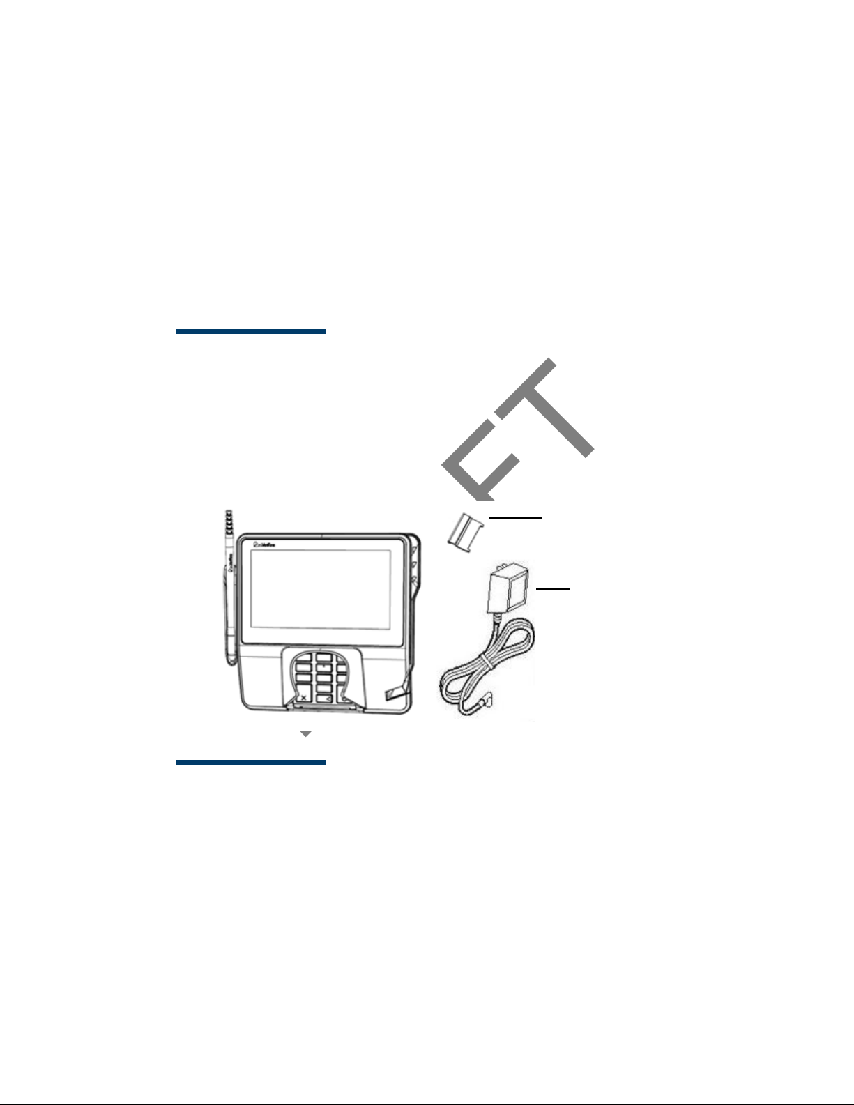
Berg Ret ai ner
Power Pack
(Separat e Cart on)
Thi s chapt er describes t he MX 900 Ser ies i nst allation procedur es and incl udes
connect ion examples.
Installing the Device
Thi s sect ion present s inst allation gui deli nes f or t he MX 900 Series t erminal.
Unpacking
Open the shippi ng cart on and caref ul ly i nspect t he content s for possible
t ampering or shippi ng damage.
Warni ng:Do not use a damaged termi nal .
To unpack t he shipping carton
1. Wit h t he shipping carton ri ght side up, open t he t op and remove al l i t ems
from the carton:
– Terminal unit
– Power pack (Separat e Packaging)
–Berg retainer
2. Remove t he prot ect ive plast ic wrap f r om t he displ ay and ot her
component s.
March 1, 2012
Page 10

DRAFT
4 MX 900 Series Installation Guide
3. Place the component s on a tabl e or countertop.
4. Save t he shipping car t ons and packing mat erial for repacking or moving
in t he fut ur e.
Selecting a Location
Warni ng:
Use t he followi ng guidel ines t o sel ect a l ocation f or t he MX 900 Ser ies termi nal .
1. Sel ect a locat ion for the terminal t hat of f ers adequat e ventilat ion and
2. Place t he MX 900 Series t er minal on a f lat surface, such as a t abl e or
The MX 900 Ser ies termi nal i s designed f or indoor use only.
prot ect ion and is conveni ent f or t he user and merchant .
count er t op, or mount it on a mount ing st and suppl ied by Veri Fone. Avoid
areas wi t h:
– Excessive heat or dust
– Oil or moi sture
– Devices t hat cause excessive voltage f l uct uat ions or el ectrical noise,
such as air condit ioner s, fans, elect r ic mot or s, neon signs, or hi ghfrequency secur it y devi ces must be no cl oser t han 24 i nches
– Direct sunl ight or obj ect s t hat r adiat e heat
Note: Interference Sources:
Special care i s requi red when mount i ng the MX 900 Series
t er minal in sites t hat utili ze ant i-t heft devices posit ioned at
doorways or surface mount ed deact ivat or pads. Devices of t hi s
t ype, such as Sensormat ic brand devices, generat e strong
el ect romagnetic f ields which may i nt erfere w it h MX 900 Series
t er minal s. Alw ays select mounting locat i ons at least 6 feet from
doorway units and at l east 18 inches f rom surface mounted
deact ivat or pads.
Note: Mounting Considerat ions:
VeriFone recommends t he use of an appr oved stand for al l
mount ing situat ions. Posit ion t he t er minal convenient l y in
relation t o power, ECR and LAN connect ions. Ensur e the MX 900
Ser ies t er mi nal i s locat ed i n a manner t hat al lows cust omers t o
swipe t hei r magnet ic cards or i nsert t hei r Smart Cards in a
smoot h and comfort abl e mot ion w it hout encountering
obst ruct ions. If t he uni t wi ll be swiveled during normal oper at i on,
VeriFone requi res t he use of an approved swivel st and. The st and
must l imi t the swivel t o 180 degrees t o pr event t wist ing and
damage t o t he MX 900 Ser ies cable. Af t er mounting, verif y all
cables move f r eely and do not twi st when t he unit i s rot at ed
t hr oughout it s range of motion.
March 1, 2012
Page 11
DRAFT
MX 900 Series Installation Guide 5
Warni ng:Do not use t he MX 900 Ser ies t er mi nal near wat er, including a
bat ht ub, wash bowl, kit chen sink, or l aundry t ub. Do not use
in a wet basement or near a swi mming pool.
3. Before connect ing the termi nal t o the power pack, complete t he
inst al lat ion by connect ing al l t he cables (see Connecting t he Devi ce and
Power Up with t he Mult ipor t Cabl e).
Stand Mount
In most r et ai l spaces, t he t er minal is positioned on a st and mount . To inst all t he
t er minal on t he st and mount :
1. Inst all t he st and mount on t he count er t op in t he desired l ane over an
appropri at e hol e t hr ough which t he wi ring connect ions can be t hr eaded.
2. Thr ead all wir ing connect ions t hrough t he cent er of t he stand mount .
3. Make all wir ing connections.
4. Ali gn and seat the t hree pins on t he t op pl at e of t he st and mount
pl at f or m wit h the three key- hol e slot s on t he bot t om of t he t er minal .
5. Sl ide the termi nal down until t he uni t seat s secur el y.
6. Position t he st and so t hat it is protect ed f rom bei ng bumped by shopping
car t s or ot her items. Being bumped and pot ential l y trigger t he syst em
int o “ t hi nking” a breach att empt has occurred, causing t he encrypt i on
keys t o be cleared.
March 1, 2012
Page 12
DRAFT
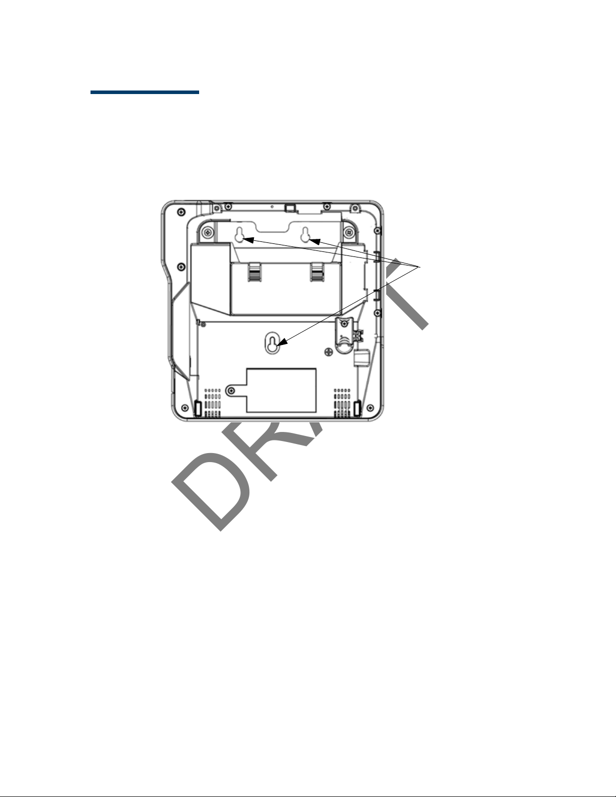
6 MX 900 Series Installation Guide
Key Hole Slots
Mounting Holes
Wall Mount
The MX 900 Ser ies t erm inal can be mount ed on a wall. To wal l mount t he MX 900
Ser ies t ermi nal :
1. Creat e a t empl at e of t he t hr ee key hole slot s on t he bott om of the
MX 900 Series t erminal.
2. Locat e a wall st ud t o base cent er placement of t he MX 900 Series
t er minal unit .
3. Mark the hole placement on t he desir ed wall locat ion.
4. Prepare holes f or screw pl acement. For mount ing int o drywall use 1/ 8"
Hollow Wal l Anchors. Other stud mount ings use #6 trim screws. After
inst al lat ion appl y 30 pounds force downward t o ensure pr oper mount ing.
a. Creat e a small hol e in which t o screw in sel f -tappi ng wood screws, or
b. Insert molly screws int o prepared holes in sheet rock wal l.
5. Insert screws i nt o prepared holes, leaving approximat el y 6.35mm (1/ 4” )
of t he screw above t he level of t he wall.
Note: Adj ust t he screw dept h t ill t he uni t is f irmly mount ed.
6. Ali gn and seat screws in t he key hol e slot s.
7. Sl ide the MX 900 Series t erminal dow n unt il t he uni t seat s secur ely.
March 1, 2012
Page 13

DRAFT
MX 900 Series Installation Guide 7
PIN Protect ion Measures
The followi ng techniques can be employed t o provide for ef f ective screeni ng of
t he PIN-ent ry keypad during the PIN-entry process. These met hods would
t ypically be used in combi nat ion, though in some cases a met hod might be used
singly.
■ Positioning of terminal on t he check-stand in such a way as t o make visual
observat i on of t he PIN-ent ry process inf easible. Examples include:
– Visual shields designed int o t he check-st and. The shields may be
sol el y for shielding purposes, or may be part of t he general checkst and design.
– Position t he PIN Ent ry Device (PED) so t hat i t is angled in such a way
t hat PIN spying is dif f i cult .
■ Inst alling PED on an adj ust able stand t hat allows consumers t o swivel t he
t er minal sideways and/ or t ilt it forw ards/ backwards t o a position t hat
makes visual observat ion of t he PIN-ent r y process di f f icul t .
■ Positioning of in-store secur it y cameras so t hat t he PIN-entry keypad is
not visible.
The followi ng table descri bes t he t wo pref err ed mount ing met hods and t he
recommended measure t o pr ot ect from PIN capt ur e in four observat i on
cor ridors:
Mounting Methods and Protection Measures
Method Cashier Customer Queue
Countertop wit hout
st and
Countertop wi t h
St and
VeriFone also recommends instruct ion of t he car dholder r egarding safe
PIN-ent ry. This can be done wi t h a combination of :
■ Si gnage on t he PED
■ Prompt s on t he di splay, possi bly wi t h a “ click-through” screen
■ Literature at t he point of sale
■ A logo f or safe PIN-entry process
Use signage
behind t he PED
No Act i on
Needed
Inst all so that customer is
bet ween PED and next i n queue
Inst all so that customer is
bet ween PED and next i n queue
Note: For a det ailed discussion of PINpad Securit y Best Pract ices, see t he
MX 900 Ref er ence Manual .
March 1, 2012
Page 14

DRAFT
8 MX 900 Series Installation Guide
Installing Optional Component s
Thi s sect ion discusses t he inst allat ion procedures f or t he opt ional component s
available f or the MX 900 Series t ermi nal . Your t ermi nal may alr eady have some
of t hese opt i ons, as modules can be inst al led at the fact ory or in t he f ield.
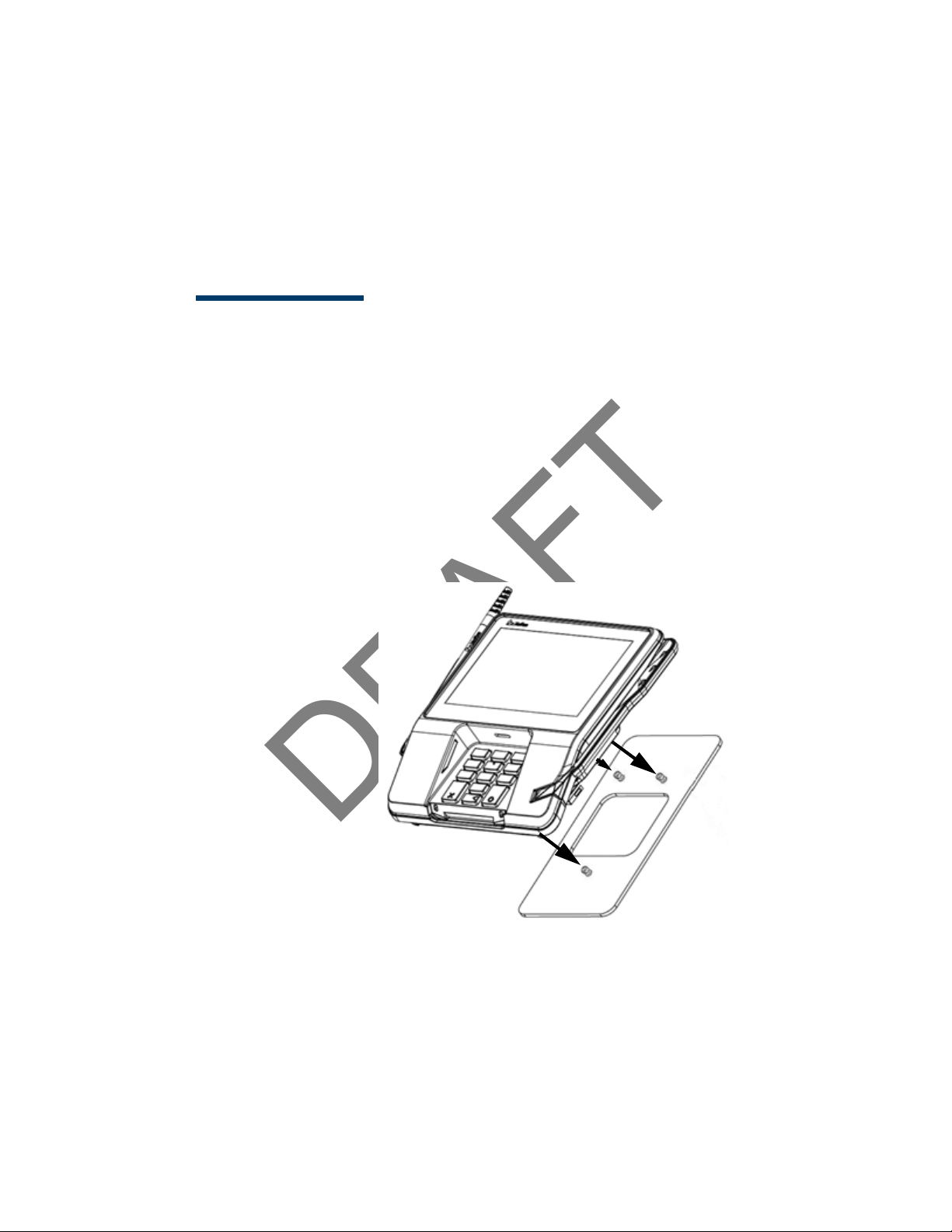
Installing Countertop Wedge
The count ert op wedge rai ses t he rear sect ion of t he MX 900 Series t ermi nal by
an angle of 10 degrees t o facilit at e use of t he screen. See the St and Mount
section f or ali gning t he pins.
To install the countertop wedge
1. Ali gn the pins in t he count ert op wedge wi t h t he t wo key holes on the
bot t om of t he MX 900 Series t ermi nal .
2. Sl ide the countert op wedge firml y into posit i on.
March 1, 2012
Page 15

DRAFT
MX 900 Series Installation Guide 9
Ta b s
Ta b s
Removing or Installing the I/O Module
Use the foll owing st eps t o remove and i nstall I/ O modul es.
Push down t he t wo t abs so t hat t he I/ O modul e can slide out.
March 1, 2012
Page 16

DRAFT
10 MX 900 Series Installation Guide
Sl ide the module i n unt i l it locks int o place.
I/ O Modules
Terminal Description Terminal P/N I/ O Module P/ N
MX 915
MX 925
AUD, BERG ONLY, NO
TAIL GATE
PWR, AUD, BERG W/
TAILGATE, ETH, USB OTG,
COM 2
PWR, AUD, POE, USB OTG,
USB HOST, COM 1, COM 2
PWR, AUD, ETH, USB OTG,
COM 1, WIFI/ BT
AUD, BERG ONLY, NO
TAIL GATE
PWR, AUD, BERG W/
TAILGATE, ETH, USB OTG,
COM 2
PWR, AUD, POE, USB OTG,
USB HOST, COM 1, COM 2
PWR, AUD, ETH, USB OTG,
COM 1, WIFI/ BT
P132-601-00-R MX900-01
P132-602-00-R MX900-02
P132-603-00-R MX900-03
P132-604-00-R MX900-04
P132-601-00-R MX900-01
P132-602-00-R MX900-02
P132-603-00-R MX900-03
P132-604-00-R MX900-04
Installing MSAM or SD Cards
Foll ow t he st eps below to i nst all smart cards (MSAM or SD cards).
Oft en merchant s are issued MSAM or SD car ds t o run small applications, such as
loyalt y programs. MSAM and SD cards are used only wit h MX 900 Series t erminal
smart card configur at i ons.
1. Unpl ug the power pack f rom the mul t i port cabl e or unplug from t he I/ O
module i f no multiport cable is present .
2. Place t he t er minal upside down on a soft , clean surface to protect the
glass cover f rom scrat ches.
March 1, 2012
Page 17

DRAFT
MX 900 Series Installation Guide 11
3. Remove t he car d compartment door screw and rotat e the door up and
back t o access the SD and MSAM cardholder s.
4. Remove any previously install ed MSAM or SD car d by sliding t he card f rom
t he car dholder.
March 1, 2012
Page 18

DRAFT
12 MX 900 Series Installation Guide
Note: Bef ore insert ing t he SD or MSAM car d, posit ion i t wi t h t he card’s
gold cont acts f acing the smart card reader end of t he t erminal.
The cardholder connect or base has a set of contact s and a not ch
on one corner t o ensure t he card is posit ioned correct ly. The card
has a not ch on one cor ner to ensure that it f its i nt o t he connector
base i n only one way. The card compart ment door w ill not close
properl y if the cards are installed incorr ect ly.
5. Inst all an MSAM or SD car d by aligni ng t he card and carefully sliding it
wit hin t he guides on t he cover unt i l it i s fully insert ed.
March 1, 2012
Page 19

DRAFT
MX 900 Series Installation Guide 13
6. Reinst al l t he compart ment cover and door screw.
March 1, 2012
Page 20

DRAFT
14 MX 900 Series Installation Guide
Installing the St ylus and Holst er
Use the foll owing st eps t o inst al l t he stylus and it s hol ster.
1. Turn t he MX 900 Ser ies t er mi nal over and pl ug the stylus cable int o the
t op of the terminal and i nsert and t ight en screw.
March 1, 2012
Page 21

DRAFT
MX 900 Series Installation Guide 15
2. Locat e the two screw hol es f or at t aching t he holst er. Rout e t he st ylus
cable t hr ough a channel in t he hol st er and then at t ach t he holst er using
t he t wo screws. The cable shoul d be in t he channel bet ween t he hol ster
and t he t er minal.
March 1, 2012
Page 22

DRAFT
16 MX 900 Series Installation Guide
Pri vacy Shield
Removing the Privacy Shield
To remove t he privacy shield, pull on each side of the privacy shield until it
di sconnect s from each of t he t hr ee connect i on poi nt s.
Warni ng: Once the privacy shield i s removed, it cannot be re-installed.
March 1, 2012
Page 23

DRAFT
MX 900 Series Installation Guide 17
Connecting the Device
Thi s sect ion provides bri ef descriptions of possible MX 900 Series t erminal device
connect ions and t he power pack connect i on. For complet e inform at ion about
inst al ling and using an opt ional device, see t he user documentat ion suppli ed
wit h t hat device.
Ensure t hat t he multiport cable or I/ O module is not connect ed t o a power pack
before at t aching t o the MX 900 Seri es t er minal.
I/ O Module
The MX 900 Series termi nal s use one of f our I/ O Modules wit hout t he mul t i port
cable t o make t he f ollowi ng connect ions:
Note: Use t he Et her net port on t he I/ O module onl y if t he mult iport cable i s
not at t ached. Ot herwise, use t he Et her net port on the mul t ipor t cabl e.
Connection I/ O Module 1 I/ O Module 2 I/ O Module 3 I/ O Module 4
Power Jack XXXX
Audio Jack XXXX
Berg X X
Ta i l g a t e / Co m 3 X
Et hernet X
Power Over Ethernet X X
USB 2.0 Device X X X
USB 1.1 Host X X
COM1 X X
COM2 XXX
March 1, 2012
Page 24

DRAFT
18 MX 900 Series Installation Guide
USB
Power
Audio
Berg
Et hernet
COM2
Example of connect i ons t o t he I/ O Module (I/ O Modul e 2 show n bel ow)
Multiport Cable
The MX 900 Series termi nal s use a mult ipor t cabl e to make the foll ow ing
connect ions:
■ ECR
■ Et hernet LAN
■ Development / host PC
■ Ser ial cable
■ USB
■ USB device
■ Power inp ut
■ Audio out put
Note: Some multiport cables r equire addit i onal cabl ing t o wor k; for example a
pi gt ail for cer t ai n port s or Et hernet cable.
March 1, 2012
Page 25

DRAFT
MX 900 Series Installation Guide 19
Caut ion: Improper i nst allation or removal of t he t ermi nal connect or may
permanent ly damage t he MX 900 Series t erminal.
The followi ng precaut ions must be t aken w ith mul t ipor t cabl es:
■ Use the Et hernet port on t he IO modul e only if the mul t i port cabl e is not
at t ached. Ot herwise, use t he Ethernet port on t he multiport cable.
■ Do not force t he t erminal connect or int o pl ace.
■ Alw ays make sure t hat al l of t he pins are lined up in correct parallel
fashion before applying light pr essure t o snap the terminal connector int o
pl ace.
■ Do not att empt to r emove t he t ermi nal connect or by pulli ng directly on
t he cable. Instead, fir mly grasp t he sides of the terminal connector wit h
t humb and forefinger, t hen pull out at t he same angl e the connect or on
t he t er minal is f aci ng.
■ Disconnect ing t he power sour ce dur ing t ransact ion processing may cause
loss of t ransact ion dat a.
March 1, 2012
Page 26

DRAFT
20 MX 900 Series Installation Guide
Ret ai ner
(Slides over Ber g)
Connecting ECR in Tailgate Mode
To connect an ECR t o the MX 900 Seri es t erminal, insert t he multiport cable pl ug
int o the bot t om socket on t he t erminal and inst al l t he ret ai ner. Then connect
t he RS485 tailgat e connect or to t he desired 12-volt port on t he back of the IBM
regist er, such as 9A or 9B.
Caut ion: Use caut i on because the various ports on t he back of t he regist er
have di f f erent volt ages. Plugging int o t he wr ong port may damage
t he regist er or t he MX 900 Ser ies t er mi nal .
March 1, 2012
Page 27

DRAFT
MX 900 Series Installation Guide 21
Connecting to a Host PC
To connect t he MX 900 Series t erminal t o a development PC, which shows a USB
connect ion w it h the 23741-02-R mult iport cable. Not e t hat USB dr ivers ar e
requi red t o support t his confi gurat ion.
Connecting to the Ethernet LAN
Connecting to USB Host or Hub
March 1, 2012
To connect t he MX 900 Ser ies t erminal t o an Ether net LAN t hrough t he Et her net
por t using a st andard Ethernet cable, insert t he LAN cable f rom t he LAN rout er
or hub i nt o t he Et her net port on t he mult ipor t cabl e.
Connect i ng t o a USB host or hub r equires Ver iFone USB cabl e (P/ N 23741-02-R).
To connect t o a USB host or hub:
1. Insert t he mul t i port cable plug int o the bot t om socket on t he t erminal,
secure wit h t he t i e-down st rap, and route t he cable t hr ough t he slot s t o
t he desired exit side.
2. Plug t he USB connect or of t he mult iport cabl e int o t he USB host or hub.
Page 28

DRAFT
22 MX 900 Series Installation Guide
Pow er ing u p
Thi s sect ion descri bes how t o connect the MX 900 Seri es t er minal to a power
source using the mul t i port cable or I/ O Modul e.
Note: If connect ed t o an ECR, t he MX 900 Series t er minal can r eceive power
from the ECR.
Warni ng:Do not plug t he pow er pack int o an outdoor out l et or operate t he
t er minal out doors.
Note: The power out l et should be on a dedicat ed ci rcuit or on an
uni nt erruptible power supply (UPS). If ot her devices are plugged int o the
same ci rcui t , the MX 900 Series device can pot ent iall y experience power
fluct uations t hat might cause it t o mal f unct ion.
Using the I/O Module
1. Make all ot her connect i ons before connect ing t he power pack.
2. Insert t he plug from t he pow er pack int o t he +12V receptacle on t he I/ O
module.
3. Plug t he pow er pack into an indoor elect r ical power out let .
March 1, 2012
Page 29

DRAFT
MX 900 Series Installation Guide 23
Using t he Multiport Cable
1. Make all ot her connect i ons before connect ing t he power pack.
2. Insert t he mult iport cable connect or i nt o the port on t he back of t he
t er mi nal and secure w ith t he Berg ret ainer.
3. Rout e t he cable t hr ough t he slot s t o the desir ed exi t side.
4. Insert t he plug f r om t he power pack int o the +12V r ecept acle on t he
mult ipor t cable.
5. Plug t he pow er pack into an indoor elect r ical power out let .
March 1, 2012
Page 30

DRAFT
24 MX 900 Series Installation Guide
Calibrate Touch Screen
The MX 900 Ser ies t ermi nal r equires a touch screen calibrat i on at t he t ime of
inst al lat ion. The t ermi nal should be pow ered on and al l owed to st abi lize at
nor mal oper at i ng temperature; usually t his t akes no longer t han 30 minut es,
even if t he t er minal was previously in a cool er or war mer locat ion. The t ouch
scr een cali brat ion procedure (bel ow) should t hen be performed. Also, while in
Syst em Mode, verif y t he t ime on t he uni t is cor rect .
To perf orm a t ouch screen (panel) calibrat ion, f oll ow t hese procedures:
Primary Method:
1. Press t he 1, 5, and 9 keys at t he same t i me t o ent er System Mode.Keep
hands aw ay from the display unt i l t he prompt appears f or passw or d
ent ry.
2. Ent er the Syst em Mode passw ord.
3. In System Mode, perf or m a manual t ouch screen compensat ion. Tap
Admi ni strat ion > Touch Panel > Go. Follow t he direct ions on t he displ ay.
Note: i f t he t ouch panel is completely unresponsive af t er logging in,
press ‘ 1’ and ‘ ent er’ to perform t he cal ibrat ion.
Alternat e Method:
Thi s met hod does not r equir e know ledge of syst em password.
1. Press ‘ Red X’ (cl ear ) key pr ior t o ent eri ng any digi t s on password screen.
The menu screen di spl ays t he f ol lowing opt i ons.
– 1 - Run Appli cat ion
– 2 - Perform Cali br at i on
– X - Return t o Login Screen
2. Press ‘ 2’ key t o perform screen calibration.
3. After cal ibr at ion is complete, press ‘ 1’ t o run cust omer application or ‘ X’
t o return t o password menu screen. If no keys are pressed wi t hi n a f ew
seconds, t he t erminal wil l automat ically r et urn t o t he password menu
scr een.
March 1, 2012
Page 31

DRAFT
3 MAINTENANCE
The MX 900 Ser ies t ermi nal has no user-maint ainabl e part s. The smar t card
impl ement ation i s a pr opr iet ary hardware sol ut ion t hat has no serviceable par t s.
Cleaning the Terminal
To clean t he t erminal, use a clean clot h slight ly dampened wit h wat er and a
drop or t w o of mil d soap. For st ubborn st ains, use al cohol or an alcohol-based
cl eaner. For best results, use t he VeriFone Cleaning Kit (P/ N 02746-01).
Note: Never use t hi nner, t r i chloroet hylene, or ketone-based solvent s as
t hey may det er iorat e plast ic or rubber part s. Do not spray cl eaners
or ot her solut ions di rect ly ont o the display.
Cleaning t he Display Screen
Spray a non-scrubbing cleaner ont o a cl ot h or paper t ow el and t hen clean t he
scr een wit h it . Do not spray cleaner s or ot her solutions direct l y ont o t he displ ay.
Magnet ic Stripe Cleaner
Smart Card Reader
March 1, 2012
Dirt can lead t o magnet i c stripe car d reading problems. The magnet ic st ripe
reader (MSR) should be cl eaned on a regular basis using commercial ly avail able
card cleaning cards. VeriFone cleani ng card P/ N 02746-01 is r ecommended.
Cleani ng t he MSR should be down anywhere f rom dai ly, t o once a w eek
depending on t he volume of t er mi nal usage.
Do not att empt to clean t he smar t card r eader. Doing so may void t he warr ant y.
For smar t card reader service, cont act your Ver iFone di stribut or or service
provi der.
Page 32

DRAFT
26 MX 900 Series Installation Guide
March 1, 2012
Page 33

DRAFT
4 TERMINAL SPECIFICATIONS
Terminal Specifications
Thi s chapt er discusses pow er requirement s, di mensions, and ot her
specifications of t he MX 900 Ser ies t ermi nal s.
Power
Environment al
Dimensions
Wei ght
• Power pack output requirements: 12W, 12-24VDC.
• Power pack input requirements: 100-240VAC, 50/60Hz.
• Operating temperature: 0° to 40° C (32° to 104° F)
• Storage temperature: – 18° to + 66° C (0° to 150° F)
• Humidity: 15% to 95% relative humidity; no condensation
MX 915
• Height: 56 mm (2.2 inches)
• Width: 182 mm (7.2 inches)
• Depth: 225 mm (8.9 inches)
MX 925
• Height: 56 mm (2.2 inches)
• Width: 218 mm (8.6 inches)
• Depth: 230 mm (9.1 inches)
MX 915: 1.3 lbs. (0.6 kg)
MX 925: 2.0 lbs. (0.9 kg)
March 1, 2012
Page 34

standby mode reducing power draw. Additional feature requirements
used for product must meet the requirements as by the quality
Hardware Requirements
Speaker/Buzzer Speakers for Razor (stereo line out)
Speaker Mini Razor (Mono Line out)
Display 4.3", 7"
USB Display capable for ECR type applications -
Dimmable LED's, HW must be capable of going into a hibernate or
Green
Screen size
requirements
Battery Shelf
Life
Wireless Antenna needs to either be integrated or appear as if it is. Stand
Contactless integrated into display screen/or hidden antenna - NO modular
USB Host and Device support
Additional
communication
are documented in the Green tab in this document
Materials used must comply with all recycling as noted on the Green
tab
All screens >4.3" request for E* Compliancy
Larger screen options > 5.7"
>5yrs min 40k hours (Shelf Life)
cannot interfere with operation
antenna as in the Spectrum Plus series
Modularized FRU solution that is hidden from the customer
RFID, Bluetooth, RS232 to BT (using serial to emulate BT)
options
External Flash
Memory
support
Power supply Locking power supply integrated into chassis / Same power supply
Plastic
requirements
Upgradable locking/hidden USB, Memory stick or Micro SD upgrade
up to 32 GB
MX housing needs to support for a slot for an SD Memory card up to
32GB - No Payment Data
across all MX platforms / Can be done through wire management -
power supply cannot become inadvertantly unplugged
Would like to standardize on one power supply for VX and MX
products - cannot be done
Power supply for Todays MX needs to be backwards compatibility
POE
PO-USB - Power Over USB - Europe request
Plastics
team for robustness
Page 35

locking
For Kiosk applciations there needs to be an optional locking
mechanism
Touch Panel Touchpanel support - either stylus / finger input during signature
Signature
Capture
Reset Retain paperclip method of reset
mechanism that will put the unit into a state where it can only be
unlocked by a manager or store administrator the unit if removed
without releasing the lock prior to removal. This needs to be an "opt
in" feature by the customer.
capture with palm rejection in stylus mode
Signature capture capability that supports not only speed but also
pressure (and/or other biometric measures supported by signature
pads) - Can be done through the stylus at an added cost - Need to
ensure that componentry is available does not necessarily need to be
ready at launch time.
Page 36

DRAFT
28 MX 900 Series Installation Guide
March 1, 2012
Page 37

Federal Communication Commission Interference Statement
This device complies with Part 15 of the FCC Rules. Operation is subject to
the following two conditions: (1) This device may not cause harmful
interference, and (2) this device must accept any interference received,
including interference that may cause undesired operation.
This equipment has been tested and found to comply with the limits for a
Class B digital device, pursuant to Part 15 of the FCC Rules. These limits
are designed to provide reasonable protection against harmful interference in a
residential installation. This equipment generates, uses and can radiate radio
frequency energy and, if not installed and used in accordance with the
instructions, may cause harmful interference to radio communications.
However, there is no guarantee that interference will not occur in a particular
installation. If this equipment does cause harmful interference to radio or
television reception, which can be determined by turning the equipment off
and on, the user is encouraged to try to correct the interference by one of the
following measures:
- Reorient or relocate the receiving antenna.
- Increase the separation between the equipment and receiver.
- Connect the equipment into an outlet on a circuit different from that
to which the receiver is connected.
- Consult the dealer or an experienced radio/TV technician for help.
FCC Caution: Any changes or modifications not expressly approved by the
party responsible for compliance could void the user's authority to operate this
equipment.
This transmitter must not be co-located or operating in conjunction with any
other antenna or transmitter.
Radiation Exposure Statement:
This equipment complies with FCC radiation exposure limits set forth for an
uncontrolled environment. This equipment should be installed and operated
with minimum distance 20cm between the radiator & your body.
Page 38

DRAFT
INDEX
A
acr onym s, Inst al lat i on Gui de
2
audience, Inst all at ion Guide
1
C
connect ing
ECR Tai lgat e 20
Et hernet LAN 21
I/ O module 17
mult ipor t cables 18
t o Host PC 21
t o USB host or hub 21
cou nt er t op wed ge, i nst al l ing
8
E
ECR connection, t ailgat e
mode 20
Et hernet LAN connect ion 21
H
Host PC 21
I
I/ O module
connect ing 17
di sconnect ing 17
pow er up wit h 22
I/ O modules 9
inst al lat ion
I/ O modules 9
MSAM cards 10
MX 900 Series 3
opt ional components 8
SD car ds 10
sel ecting a l ocation 4
st and mount 5
wall mount 6
L
locat i on for MX 900 Series 4
M
mai nt enance
cl eani ng a t er minal 25
smart card r eader 25
MSAM cards, inst alling 10
mult ipor t cables
connect ing 18
di sconnect ing 18
pow er up wit h 22
MX 900 Series
har dware installat ion 3
specifications 27
O
opt ional components
count ert op wedge 8
I/ O modules 9
inst al lat ion 8
MSAM cards 10
SD car ds 10
P
PIN prot ection measur es 7
pow er up
wit h I/ O modul e 22
wit h multiport cable 22
S
SD car ds, installi ng 10
specificat ions, MX 900 Ser ie s
27
st and mount f or MX 900
Ser ies 5
U
USB
connect ion 21
W
wall mount for MX 900 Seri es
6
March 1, 2012
Page 39

DRAFT
30 MX 900 Series Installation Guide
March 1, 2012
 Loading...