

Page 1
DRAFT
MX 900 Series
Installation Guide
Page 2

DRAFT
Page 3

DRAFT
MX 900 Series Installation Guide
Part Number SPC132-022-01-A, Revision A
March 1, 2012
VeriFone®, Inc.
2099 Gateway Place
Suite 600
San Jose, CA 95110
Telephone: 408-232-7800
http://www.verifone.com
Printed in the United States of America.
© 2012 by VeriFone, Inc.
No part of this publication covered by the copyrights herein may be reproduced or copied in
any form or by any means — graphic, electronic, or mechanical, including photocopying,
taping, or information storage and retrieval systems — without written permission of the
publisher.
The contents of this document and all features and specifications are subject to change
without notice. The information contained herein does not represent a commitment on the
part of VeriFone, Inc.
Publications are not stocked at the address given above. Requests for VeriFone publications
should be made to your VeriFone representative.
V eriFone, the V eriFone logo, and Ruby SuperSystem are registered trademarks of V eriFone, Inc.
Sapphire, Topaz, HPV-20, Ruby Manager, Everest, E
Card are trademarks of Veri Fone, Inc. in the U.S. and/or other countries. All other trademarks
or brand names are the properties of their respective holders.
ASY ID, Electronic Journal On-site, and Ruby
Page 4

DRAFT
Page 5

DRAFT
Contents
1. Introduction. . . . . . . . . . . . . . . . . . . . . . . . . . 1
Modifications to this document . . . . . . . . . . . . . . . . . . . . 1
Acronyms, Abbreviatio ns, and Definitions . . . . . . . . . . . . . 2
2. Hardware Installation . . . . . . . . . . . . . . . . . . . 3
Installing the Device . . . . . . . . . . . . . . . . . . . . . . . . . . . 3
To unpack the shipping carton. . . . . . . . . . . . . . . . . . . . . 3
Selecting a Loca tion . . . . . . . . . . . . . . . . . . . . . . . . . . . 4
Stand Mount. . . . . . . . . . . . . . . . . . . . . . . . . . . . . . . . . 5
Wall Mount. . . . . . . . . . . . . . . . . . . . . . . . . . . . . . . . . . 6
PIN Protection Measures . . . . . . . . . . . . . . . . . . . . . . . . . 7
Installing Optional Components . . . . . . . . . . . . . . . . . . . . 8
Connecting the Device . . . . . . . . . . . . . . . . . . . . . . . . . 17
Powering up. . . . . . . . . . . . . . . . . . . . . . . . . . . . . . . . 22
Calibrate Touch Screen . . . . . . . . . . . . . . . . . . . . . . . . 24
Intended Audience . . . . . . . . . . . . . . . . . . . . . . . . . . 1
Document Organization . . . . . . . . . . . . . . . . . . . . . . . 1
Installing Countertop Wedge. . . . . . . . . . . . . . . . . . . . 8
Removing or Installing the I/O Module . . . . . . . . . . . . . 9
Installing MSAM or SD Cards . . . . . . . . . . . . . . . . . . . 10
Installing the St ylus and Holster . . . . . . . . . . . . . . . . 14
Removing the Privacy Shield . . . . . . . . . . . . . . . . . . . 16
I/O Module . . . . . . . . . . . . . . . . . . . . . . . . . . . . . . 17
Multiport Cable . . . . . . . . . . . . . . . . . . . . . . . . . . . 18
Connecting ECR in Tailgate Mode. . . . . . . . . . . . . . . . 20
Connecting to a Host PC. . . . . . . . . . . . . . . . . . . . . . 21
Connecting to the Ethernet LAN . . . . . . . . . . . . . . . . 21
Connecting to USB H ost or Hub . . . . . . . . . . . . . . . . . 21
Using the I/O Module. . . . . . . . . . . . . . . . . . . . . . . . 22
Using the Multiport Cable. . . . . . . . . . . . . . . . . . . . . 23
3. Maintenance . . . . . . . . . . . . . . . . . . . . . . . . . 25
March 1, 2012
Page 6

DRAFT
ii MX 900 Series Installation Guide
Cleaning the Terminal. . . . . . . . . . . . . . . . . . . . . . . . . . 25
Cleaning the Display Screen . . . . . . . . . . . . . . . . . . . . . . 25
Magnetic Stripe Cleaner. . . . . . . . . . . . . . . . . . . . . . . . . 25
Smart Card Reader . . . . . . . . . . . . . . . . . . . . . . . . . . . . 25
4. Terminal Specifications. . . . . . . . . . . . . . . . . . 27
Terminal Specifications. . . . . . . . . . . . . . . . . . . . . . . . . 27
March 1, 2012
Page 7

DRAFT
1 INTRODUCTION
This installation guide is your primary source of information for setting up and
installing the MX 900 Series terminals, the MX 915
Intended Audience
This guide is useful for anyone installing and configuring the MX 900 Series
terminals. A basic description of terminal features is also provided.
Document Organization
The following chapters are included:
Chapter 1, Introduction, explains the Intended Audience, Document
Organization, and common acronyms, abbreviations, and definitions used.
Chapter 2, Installation, explains how to install the MX 900 Series terminals.
Chapter 3, Maintenance, explains how to maintain your MX 900 Series terminals.
Chapter 4, Specifications, provides information on power, environment, and
dimensions of the hardware.
Modifications to this document
™
and MX 925™.
This document may be changed or extended to include new product
requirements.
March 1, 2012
Page 8

DRAFT
2 MX 900 Series Installation Guide
Acronyms, Abbreviations, and Definitions
The following table describes the common acronyms, abbreviations, and
definitions used:
Convention Meaning
BFI Buffer Flush Interval
bps bits per second
CRC Cyclic Redundancy Check
FA File Authentication
Firmware Software in FLASH/ROM
FTP File Transfer Protocol
GISKE Global Interoperable Secure Key Exchange
iPKG The Itsy Package Management System
IPP Internal PIN Pad
ISR Interrupt Service Routine
JFFS2 Journaling Flash File System
KLK VSS Key Loading Key
KSN Key Serial Number
KVC Key Verification Code
LED Light Emitting Diode
MS Master Session
MSR Magnetic Stripe Reader
NFS Network File System
OSS Open Sound System
PED PIN Entry Device
PEK PIN Encryption Key
RFCR RF Card Reader
RRT Receive Record Threshold
RTC Real-time Clock
SAM Security Access Module
VRK VeriShield Remote Key
VSS VeriShield Security Scripts
March 1, 2012
Page 9
DRAFT
2 HARDWARE INSTALLATION
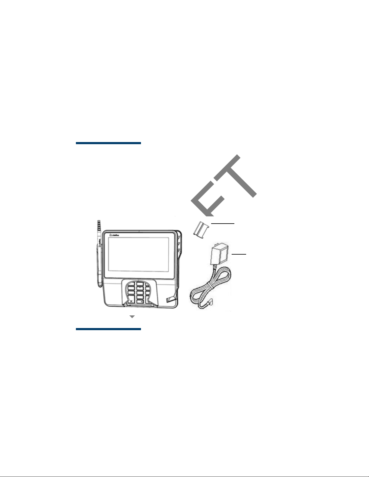
Berg Retainer
Power Pa ck
(Separate Carton)
This chapter describes the MX 900 Series installation procedures and includes
connection examples.
Installing the Device
This section presents installation guidelines for the MX 900 Series terminal.
Unpacking
Open the shipping carton and carefully inspect the contents for possible
tampering or shipping damage.
Warning:Do not use a damaged terminal.
To unpack the shipping carton
1. With the shipping carton right side up, open the top and remove all items
from the carton:
– Terminal unit
– Power pack (Separate Packaging)
–Berg retainer
2. Remove the protective plastic wrap from the display and other
components.
March 1, 2012
Page 10

DRAFT
4 MX 900 Series Installation Guide
3. Place the components on a table or countertop.
4. Save the shipping cartons and packing material for repacking or moving
in the future.
Selecting a Location
Warning:T he MX 900 Series terminal is designed for indoor use only.
Use the following guidelines to select a location for the MX 900 Series terminal.
1. Select a location for the terminal that offers adequate ventilation and
protection and is convenient for the user and merchant.
2. Place the MX 900 Series terminal on a flat surface, such as a table or
countertop, or mount it on a mounting stand supplied by VeriFone. A void
areas with:
– Excessive heat or dust
– Oil or moisture
– Devices that cause excessive voltage fluctuations or electrical noise,
such as air conditioners, fans, electric motors, neon signs, or highfrequency security devices must be no closer than 24 inches
– Direct sunlight or objects that radiate heat
Note: Interference Sources:
Special care is required when mounting the MX 900 Series
terminal in sites that utilize anti-theft devices positioned at
doorways or surface mounted deactivator pads. Devices of this
type, such as Sensormatic brand devices, generate strong
electromagnetic fields which may interfere with MX 900 Series
terminals. Always select mounting locations at least 6 feet from
doorway units and at least 18 inches from surface mounted
deactivator pads.
Note: Mounting Considerations:
V er i Fone recommends the use of an approved stand for all
mounting situations. Position the terminal conveniently in
relation to power, ECR and LAN connections. Ensure the MX 900
Series terminal is located in a manner that allows customers to
swipe their magnetic cards or insert their Smart Cards in a
smooth and comfortable motion without encountering
obstructions. If the unit will be swiveled during normal operation,
V eriFone requires the use of an approved swivel stand. The stand
must limit the swivel to 180 degrees to prevent twisting and
damage to the MX 900 Series cable. After mounting, verify all
cables move freely and do not twist when the unit is rotated
throughout its range of motion.
March 1, 2012
Page 11
DRAFT
MX 900 Series Installation Guide 5
Warning:Do not use the MX 900 Series terminal near water, including a
bathtub, wash bowl, kitchen sink, or laundry tub. Do not use
in a wet basement or near a swimming pool.
3. Before connecting the terminal to the power pack, complete the
installation by connecting all the cables (see Connecting the Device and
Power Up with the Multiport Cable).
Stand Mount
In most retail spaces, the terminal is positioned on a stand mount. To install the
terminal on the stand mount:
1. Install the stand mount on the countertop in the desired lane over an
appropriate hole through which the wiring connections can be threaded.
2. Thread all wiring connections through the center of the stand mount.
3. Make all wiring connections.
4. Align and seat the three pins on the top plate of the stand mount
platform with the three key-hole slots on the bottom of the terminal.
5. Slide the terminal down until the unit seats securely.
6. Position the stand so that it is protected from being bumped by shopping
carts or other items. Being bumped and potentially trigger the system
into “thinking” a breach attempt has occurred, causing the encryption
keys to be cleared.
March 1, 2012
Page 12
DRAFT
6 MX 900 Series Installation Guide
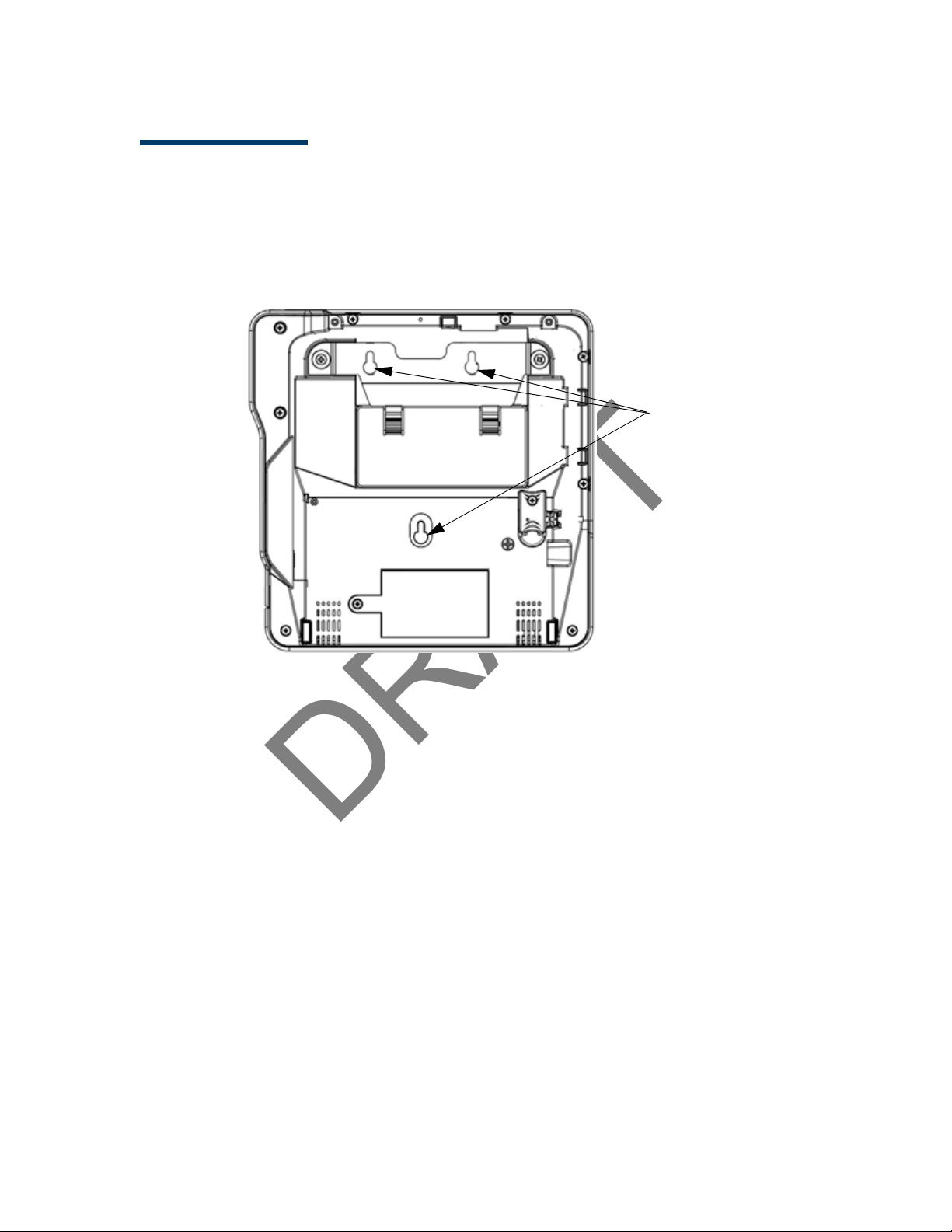
Key Hole Slots
Mounting Holes
Wall Mount
The MX 900 Series terminal can be mounted on a wall. To wall mount the MX 900
Series terminal:
1. Create a template of the three key hole slots on the bottom of the
MX 900 Series terminal.
2. Locate a wall stud to base center placement of the MX 900 Series
terminal unit.
3. Mark the hole placement on the desired wall location.
4. Prepare holes for screw placement. For mounting into drywall use 1/8"
Hollow Wall Anchors. Other stud mountings use #6 trim screws. After
installation apply 30 pounds force downward to ensure proper mounting.
a. Create a small hole in which to screw in self-tapping wood screws, or
b. Insert molly screws into prepared holes in sheet rock wall.
5. Insert screws into prepared holes, leaving approximately 6.35mm (1/4”)
of the screw above the level of the wall.
Note: Adjust the screw depth till the unit is firmly mounted.
6. Align and seat screws in the key hole slots.
7. Slide the MX 900 Series terminal down until the unit seats securely.
March 1, 2012
Page 13

DRAFT
MX 900 Series Installation Guide 7
PIN Protection Measures
The following techniques can be employed to provide for effective screening of
the PIN-entry keypad during the PIN-entry process. These methods would
typically be used in combination, though in some cases a method might be used
singly.
■ Positioning of terminal on the check-stand in such a way as to make visual
observation of the PIN-entry process infeasible. Examples include:
– Visual shields designed into the check-stand. The shields may be
solely for shielding purposes, or may be part of the general checkstand design.
– Position the PIN Entry Device (PED) so that it is angled in such a way
that PIN spying is difficult.
■ Installing PED on an adjustable stand that allows consumers to swivel the
terminal sideways and/or tilt it forwards/backwards to a position that
makes visual observation of the PIN-entry process difficult.
■ Positioning of in-store security cameras so that the PIN-entry keypad is
not visible.
The following table describes the two preferred mounting methods and the
recommended measure to protect from PIN capture in four observation
corridors:
Mounting Methods and Protection Measures
Method Cashier Customer Queue
Countertop without
stand
Countertop with
Stand
V er i Fone also recommends instruction of the cardholder regarding safe
PIN-entry. This can be done with a combination of:
■ Signage on the PED
■ Prompts on the display, possibly with a “click-through” screen
■ Literature at the point of sale
■ A logo for safe PIN-entry process
Use signage
behind the PED
No Action
Needed
Install so that customer is
between PED and next in queue
Install so that customer is
between PED and next in queue
Note: For a detailed discussion of PINpad Security Best Practices, see the
MX 900 Reference Manual.
March 1, 2012
Page 14

DRAFT
8 MX 900 Series Installation Guide
Installing Optional Components
This section discusses the installation procedures for the optional components
available for the MX 900 Series terminal. Your terminal may already have some
of these options, as modules can be installed at the factory or in the field.
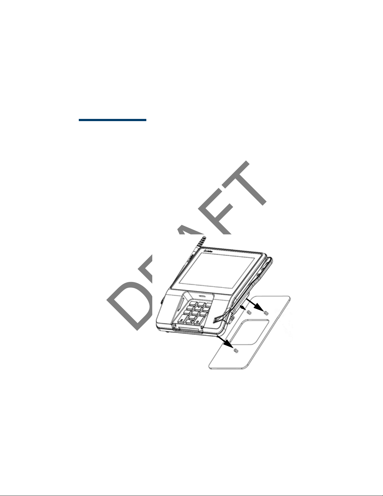
Installing Countertop Wedge
The countertop wedge raises the rear section of the MX 900 Series terminal by
an angle of 10 degrees to facilitate use of the screen. See the Stand Mount
section for aligning the pins.
To install the countertop wedge
1. Align the pins in the countertop wedge with the two key holes on the
bottom of the MX 900 Series terminal.
2. Slide the countertop wedge firmly into position.
March 1, 2012
Page 15

DRAFT
MX 900 Series Installation Guide 9
Tabs
Tabs
Removing or Installing the I/O Module
Use the following steps to remove and install I/O modules.
Push down the two tabs so that the I/O module can slide out.
March 1, 2012
Page 16

DRAFT
10 MX 900 Series Installation Guide
Slide the module in until it locks into place.
I/O Modules
Terminal Description Terminal P/N I/O Module P/N
MX 915
MX 925
AUD, BERG ONLY, NO
TAILGATE
PWR, AUD, BERG W/
TAILGATE, ETH, USB OTG,
COM 2
PWR, AUD, POE, USB OTG,
USB HOST, COM 1, COM 2
PWR, AUD, ETH, USB OTG,
COM 1, WIFI/BT
AUD, BERG ONLY, NO
TAILGATE
PWR, AUD, BERG W/
TAILGATE, ETH, USB OTG,
COM 2
PWR, AUD, POE, USB OTG,
USB HOST, COM 1, COM 2
PWR, AUD, ETH, USB OTG,
COM 1, WIFI/BT
P132-601-00-R MX900-01
P132-602-00-R MX900-02
P132-603-00-R MX900-03
P132-604-00-R MX900-04
P132-601-00-R MX900-01
P132-602-00-R MX900-02
P132-603-00-R MX900-03
P132-604-00-R MX900-04
Installing MSAM or SD Cards
Follow the steps below to install smart cards (MSAM or SD cards).
Often merchants are issued MSAM or SD cards to run small applications, such as
loyalty programs. MSAM and SD cards are used only with MX 900 Series terminal
smart card configurations.
1. Unplug the power pack from the multiport cable or unplug from the I/O
module if no multiport cable is present.
2. Place the terminal upside down on a soft, clean surface to protect the
glass cover from scratches.
March 1, 2012
Page 17

DRAFT
MX 900 Series Installation Guide 11
3. Remove the card compartment door screw and rotate the door up and
back to access the SD and MSAM cardholders.
4. Remove any previously installed MSAM or SD card by sliding the card from
the cardholder.
March 1, 2012
Page 18

DRAFT
12 MX 900 Series Installation Guide
Note: Before inserting the SD or MSAM card, position it with the card’s
gold contacts facing the smart card reader end of the terminal.
The cardholder connector base has a set of contacts and a notch
on one corner to ensure the card is positioned correctly. The card
has a notch on one corner to ensure that it fits into the connector
base in only one way. The card compartment door will not close
properly if the cards are installed incorrectly.
5. Install an MSAM or SD card by aligning the card and carefully sliding it
within the guides on the cover until it is fully inserted.
March 1, 2012
Page 19

DRAFT
MX 900 Series Installation Guide 13
6. Reinstall the compartment cover and door screw.
March 1, 2012
Page 20

DRAFT
14 MX 900 Series Installation Guide
Installing the Stylus and Holster
Use the following steps to install the stylus and its holster.
1. Turn the MX 900 Series terminal over and plug the stylus cable into the
top of the terminal and insert and tighten screw.
March 1, 2012
Page 21

DRAFT
MX 900 Series Installation Guide 15
2. Locate the two screw holes for attaching the holster. Route the stylus
cable through a channel in the holster and then attach the holster using
the two screws. The cable should be in the channel between the holster
and the terminal.
March 1, 2012
Page 22

DRAFT
16 MX 900 Series Installation Guide
Privacy Shield
Removing the Privacy Shield
To remove the privacy shield, pull on each side of the privacy shield until it
disconnects from each of the three connection points.
Warning: O nce the privacy shield is removed, it cannot be re-installed.
March 1, 2012
Page 23

DRAFT
MX 900 Series Installation Guide 17
Connecting the Device
This section provides brief descriptions of possible MX 900 Series terminal device
connections and the power pack connection. For complete information about
installing and using an optional device, see the user documentation supplied
with that device.
Ensure that the multiport cable or I/O module is not connected to a power pack
before attaching to the MX 900 Series terminal.
I/O Module
The MX 900 Series terminals use one of four I/O Modules without the multiport
cable to make the following connections:
Note: Use the Ethernet port on the I/O module only if the multiport cable is
not attached. Otherwise, use the Ethernet port on the multiport cable.
Connection I/O Module 1 I/O Module 2 I/O Module 3 I/O Module 4
Power Jack XXXX
Audio Jack XXXX
Berg X X
Tailgate / Com3 X
Ethernet X
Power Over Ethernet X X
USB 2.0 Device X X X
USB 1.1 Host X X
COM1 X X
COM2 XXX
March 1, 2012
Page 24

DRAFT
18 MX 900 Series Installation Guide
USB
Power
Audio
Berg
Ethernet
COM2
Example of connections to the I/O Module (I/O Module 2 shown below)
Multiport Cable
The MX 900 Series terminals use a multiport cable to make the following
connections:
■ ECR
■ Ethernet LAN
■ Development/host PC
■ Serial cable
■ USB
■ USB device
■ Power inpu t
■ Audio output
Note: Some multiport cables require additional cabling to work; for example a
pigtail for certain ports or Ethernet cable.
March 1, 2012
Page 25

DRAFT
MX 900 Series Installation Guide 19
Caution: Improper installation or removal of the terminal connector may
permanently damage the MX 900 Series terminal.
The following precautions must be taken with multiport cables:
■ Use the Ethernet port on the IO module only if the multiport cable is not
attached. Otherwise, use the Ethernet port on the multiport cable.
■ Do not force the terminal connector into place.
■ Always make sure that all of the pins are lined up in correct parallel
fashion before applying light pressure to snap the terminal connector into
place.
■ Do not attempt to remove the terminal connector by pulling directly on
the cable. Instead, firmly grasp the sides of the terminal connector with
thumb and forefinger, then pull out at the same angle the connector on
the terminal is facing.
■ Disconnecting the power source during transaction processing may cause
loss of transaction data.
March 1, 2012
Page 26

DRAFT
20 MX 900 Series Installation Guide
Retainer
(Slides over Berg)
Connecting ECR in Tailgate Mode
To connect an ECR to the MX 900 Series terminal, insert the multiport cable plug
into the bottom socket on the terminal and install the retainer. Then connect
the RS485 tailgate connector to the desired 12-volt port on the back of the IBM
register, such as 9A or 9B.
Caution: Use caution because the various ports on the back of the register
have different voltages. Plugging into the wrong port may damage
the register or the MX 900 Series terminal.
March 1, 2012
Page 27

DRAFT
MX 900 Series Installation Guide 21
Connecting to a Host PC
To connect the MX 900 Series terminal to a development PC, which shows a USB
connection with the 23741-02-R multiport cable. Note that USB drivers are
required to support this configuration.
Connecting to the Ethernet LAN
Connecting to USB Host or Hub
March 1, 2012
To connect the MX 900 Series terminal to an Ethernet LAN through the Ethernet
port using a standard Ethernet cable, insert the LAN cable from the LAN router
or hub into the Ethernet port on the multiport cable.
Connecting to a USB host or hub requires VeriFone USB cable (P/N 23741-02-R).
To connect to a USB host or hub:
1. Insert the multiport cable plug into the bottom socket on the terminal,
secure with the tie-down strap, and route the cable through the slots to
the desired exit side.
2. Plug the USB connector of the multiport cable into the USB host or hub.
Page 28

DRAFT
22 MX 900 Series Installation Guide
Powering up
This section describes how to connect the MX 900 Series terminal to a power
source using the multiport cable or I/O Module.
Note: If connected to an ECR, the MX 900 Series terminal can receive power
from the ECR.
Warning:Do not plug the power pack into an outdoor outlet or operate the
terminal outdoors.
Note: The power outlet should be on a dedicated circuit or on an
uninterruptible power supply (UPS). If other devices are plugged into the
same circuit, the MX 900 Series device can potentially experience power
fluctuations that might cause it to malfunction.
Using the I/O Module
1. Make all other connections before connecting the power pack.
2. Insert the plug from the power pack into the +12V receptacle on the I/O
module.
3. Plug the power pack into an indoor electrical power outlet.
March 1, 2012
Page 29

DRAFT
MX 900 Series Installation Guide 23
Using the Multiport Cable
1. Make all other connections before connecting the power pack.
2. Insert the multiport cable connector into the port on the back of the
terminal and secu re w ith the Berg retainer.
3. Route the cable through the slots to the desired exit side.
4. Insert the plug from the power pack into the +12V receptacle on the
multiport cable.
5. Plug the power pack into an indoor electrical power outlet.
March 1, 2012
Page 30

DRAFT
24 MX 900 Series Installation Guide
Calibrate Touch Screen
The MX 900 Series terminal requires a touch screen calibration at the time of
installation. The terminal should be powered on and allowed to stabilize at
normal operating temperature; usually this takes no longer than 30 minutes,
even if the terminal was previously in a cooler or warmer location. The touch
screen calibration procedure (below) should then be performed. Also, while in
System Mode, verify the time on the unit is correct.
To perform a touch screen (panel) calibration, follow these procedures:
Primary Method:
1. Press the 1, 5, and 9 keys at the same time to enter System Mode.Keep
hands away from the display until the prompt appears for password
entry.
2. Enter the System Mode password.
3. In System Mode, perform a manual touch screen compensation. Tap
Administration > Touch Panel > Go. Follow the directions on the display.
Note: if the touch panel is completely unresponsive after logging in,
press ‘1’ and ‘enter’ to perform the calibration.
Alternate Method:
This method does not require knowledge of system password.
1. Press ‘Red X’ (clear) key prior to entering any digits on password screen.
The menu screen displays the following options.
– 1 - Run Application
– 2 - Perform Calibration
– X - Ret u rn to Login Screen
2. Press ‘2’ key to perform screen calibration.
3. After calibration is complete, press ‘1’ to run customer application or ‘X’
to return to password menu screen. If no keys are pressed within a few
seconds, the terminal will automatically return to the password menu
screen.
March 1, 2012
Page 31

DRAFT
3 MAINTENANCE
The MX 900 Series terminal has no user-maintainable parts. The smart card
implementation is a proprietary hardware solution that has no serviceable parts.
Cleaning the Terminal
To clean the terminal, use a clean cloth slightly dampened with water and a
drop or two of mild soap. For stubborn stains, use alcohol or an alcohol-based
cleaner. For best results, use the VeriFone Cleaning Kit (P/N 02746-01).
Note: Never use thinner, trichloroethylene, or ketone-based solvents as
they may deteriorate plastic or ru bber parts. Do n ot spray cleaners
or other solutions directly onto the display.
Cleaning the Display Screen
Spray a non-scrubbing cleaner onto a cloth or paper towel and then clean the
screen with it. Do not spray cleaners or other solutions directly onto the display.
Magnetic Stripe Cleaner
Smart Card Reader
March 1, 2012
Dirt can lead to magnetic stripe card reading problems. The magnetic stripe
reader (MSR) should be cleaned on a regular basis using commercially available
card cleaning cards. VeriFone cleaning card P/N 02746-01 is recommended.
Cleaning the MSR should be down anywhere from daily, to once a week
depending on the volume of terminal usage.
Do not attempt to clean the smart card reader. Doing so may void the warranty.
For smart card reader service, contact your VeriFone distributor or service
provider.
Page 32

DRAFT
26 MX 900 Series Installation Guide
March 1, 2012
Page 33

DRAFT
4 TERMINAL SPECIFICATIONS
Terminal Specifications
This chapter discusses power requirements, dimensions, and other
specifications of the MX 900 Series terminals.
Power
Environmental
Dimensions
Weight
• Power pack output requirements: 12W, 12-24VDC.
• Power pack input requirements: 100-240VAC, 50/60Hz.
• Operating temperature: 0° to 40° C (32° to 104° F)
• Storage temperature: – 18° to + 66° C (0° to 150° F)
• Humidity: 15% to 95% relative humidity; no condensation
MX 915
• Height: 56 mm (2.2 inches)
• Width: 182 mm (7.2 inches)
• Depth: 225 mm (8.9 inches)
MX 925
• Height: 56 mm (2.2 inches)
• Width: 218 mm (8.6 inches)
• Depth: 230 mm (9.1 inches)
MX 915: 1.3 lbs. (0.6 kg)
MX 925: 2.0 lbs. (0.9 kg)
March 1, 2012
Page 34

standby mode reducing power draw. Additional feature requirements
used for product must meet the requirements as by the quality
Hardware Requirements
Speaker/Buzzer Speakers for Razor (stereo line out)
Speaker Mini Razor (Mono Line out)
Display 4.3", 7"
USB Display capable for ECR type applications -
Dimmable LED's, HW must be capable of going into a hibernate or
Green
Screen size
requirements
Battery Shelf
Life
Wireless Antenna needs to either be integrated or appear as if it is. Stand
Contactless integrated into display screen/or hidden antenna - NO modular
USB Host and Device support
Additional
communication
are documented in the Green tab in this document
Materials used must comply with all recycling as noted on the Green
tab
All screens >4.3" request for E* Compliancy
Larger screen options > 5.7"
>5yrs min 40k hours (Shelf Life)
cannot interfere with operation
antenna as in the Spectrum Plus series
Modularized FRU solution that is hidden from the customer
RFID, Bluetooth, RS232 to BT (using serial to emulate BT)
options
External Flash
Memory
support
Power supply Locking power supply integrated into chassis / Same power supply
Plastic
requirements
Upgradable locking/hidden USB, Memory stick or Micro SD upgrade
up to 32 GB
MX housing needs to support for a slot for an SD Memory card up to
32GB - No Payment Data
across all MX platforms / Can be done through wire management power supply cannot become inadvertantly unplugged
Would like to standardize on one power supply for VX and MX
products - cannot be done
Power supply for Todays MX needs to be backwards compatibility
POE
PO-USB - Power Over USB - Europe request
Plastics
team for robustness
Page 35

locking
For Kiosk applciations there needs to be an optional locking
mechanism
Touch Panel Touchpanel support - either stylus / finger input during signature
Signature
Capture
Reset Retain paperclip method of reset
mechanism that will put the unit into a state where it can only be
unlocked by a manager or store administrator the unit if removed
without releasing the lock prior to removal. This needs to be an "opt
in" feature by the customer.
capture with palm rejection in stylus mode
Signature capture capability that supports not only speed but also
pressure (and/or other biometric measures supported by signature
pads) - Can be done through the stylus at an added cost - Need to
ensure that componentry is available does not necessarily need to be
ready at launch time.
Page 36

DRAFT
28 MX 900 Series Installation Guide
March 1, 2012
Page 37

Federal Communication Commission Interference Statement
This device complies with Part 15 of the FCC Rules. Operation is subject to
the following two conditions: (1) This device may not cause harmful
interference, and (2) this device must accept any interference received,
including interference that may cause undesired operation.
This equipment has been tested and found to comply with the limits for a
Class B digital device, pursuant to Part 15 of the FCC Rules. These limits
are designed to provide reasonable protection against harmful interference in a
residential installation. This equipment generates, uses and can radiate radio
frequency energy and, if not installed and used in accordance with the
instructions, may cause harmful interference to radio communications.
However, there is no guarantee that interference will not occur in a particular
installation. If this equipment does cause harmful interference to radio or
television reception, which can be determined by turning the equipment off
and on, the user is encouraged to try to correct the interference by one of the
following measures:
- Reorient or relocate the receiving antenna.
- Increase the separation between the equipment and receiver.
- Connect the equipment into an outlet on a circuit different from that
to which the receiver is connected.
- Consult the dealer or an experienced radio/TV technician for help.
FCC Caution: Any changes or modifications not expressly approved by the
party responsible for compliance could void the user's authority to operate this
equipment.
This transmitter must not be co-located or operating in conjunction with any
other antenna or transmitter.
Radiation Exposure Statement:
This equipment complies with FCC radiation exposure limits set forth for an
uncontrolled environment. This equipment should be installed and operated
with minimum distance 20cm between the radiator & your body.
Page 38

DRAFT
INDEX
A
acronyms, Installation Guide
2
audience, Installation Guide
1
C
connecting
ECR Tailgate 20
Ethernet LAN 21
I/O module 17
multiport cables 18
to Host PC 21
to USB host or hub 21
countertop wedge, installing
8
E
ECR connection, tailgate
mode 20
Ethernet LAN connection 21
H
Host PC 21
I
I/O module
connecting 17
disconnecting 17
power up with 22
I/O modules 9
installation
I/O modules 9
MSAM cards 10
MX 900 Series 3
optional components 8
SD cards 10
selecting a location 4
stand mount 5
wall mount 6
L
location for MX 900 Series 4
M
maintenance
cleaning a terminal 25
smart card reader 25
MSAM cards, installing 10
multiport cables
connecting 18
disconnecting 18
power up with 22
MX 900 Series
hardware installation 3
specifications 27
O
optional components
countertop wedge 8
I/O modules 9
installation 8
MSAM cards 10
SD cards 10
P
PIN protection measures 7
power up
with I/O module 22
with multiport cable 22
S
SD cards, installing 10
specifications, MX 900 Series
27
stand mount for MX 900
Series 5
U
USB
connection 21
W
wall mount for MX 900 Series
6
March 1, 2012
Page 39

DRAFT
30 MX 900 Series Installation Guide
March 1, 2012
 Loading...