

Page 1

K450
Installation Guide
Verifone Part Number DOC500-009-EN-A, Revision A
Page 2

K450 Installation Guide
© 2021 Verifone, Inc.
All rights reserved. No part of the contents of this document may be reproduced or transmitted in any form without the written
permission of Verifone, Inc.
The information contained in this document is subject to change without notice. Although Verifone has attempted to ensure the
accuracy of the contents of this document, this document may include errors or omissions. The examples and sample programs are
for illustration only and may not be suited for your purpose. You should verify the applicability of any example or sample program
before placing the software into productive use. This document, including without limitation the examples and software programs, is
supplied “As-Is.”
Verifone and the Verifone logo are registered trademarks of Verifone. Other brand names or trademarks associated with Verifone’s
products and services are trademarks of Verifone, Inc.
All other brand names and trademarks appearing in this manual are the property of their respective holders.
Product Warranty:
For product warranty information, go to http://www.verifone.com/terms.
Comments? Please e-mail all comments on this document to your local Verifone Support Team.
Verifone, Inc.
1-800-Verifone
www.verifone.com
Verifone Part Number DOC500-009-EN-A, Revision A
Page 3

CONTENTS
PREFACE . . . . . . . . . . . . . . . . . . . . . . . . . . . . . . . . . . . . . . . 5
Audience. . . . . . . . . . . . . . . . . . . . . . . . . . . . . . . . . . . . . . . . . . . . . . . . . . . . . . . . 5
Organization . . . . . . . . . . . . . . . . . . . . . . . . . . . . . . . . . . . . . . . . . . . . . . . . . . . . . 5
Related Documentation . . . . . . . . . . . . . . . . . . . . . . . . . . . . . . . . . . . . . . . . . . . . 5
Conventions and Acronyms . . . . . . . . . . . . . . . . . . . . . . . . . . . . . . . . . . . . . . . . . 6
Document Conventions. . . . . . . . . . . . . . . . . . . . . . . . . . . . . . . . . . . . . . . . . . 6
Acronym Definitions . . . . . . . . . . . . . . . . . . . . . . . . . . . . . . . . . . . . . . . . . . . . 6
CHAPTER 1
Device Overview Features and Benefits . . . . . . . . . . . . . . . . . . . . . . . . . . . . . . . . . . . . . . . . . . . . . 8
Exceptional Ease of Use. . . . . . . . . . . . . . . . . . . . . . . . . . . . . . . . . . . . . . . . . 8
Performance and Durability . . . . . . . . . . . . . . . . . . . . . . . . . . . . . . . . . . . . . . 8
Security . . . . . . . . . . . . . . . . . . . . . . . . . . . . . . . . . . . . . . . . . . . . . . . . . . . . . . 8
Connectivity . . . . . . . . . . . . . . . . . . . . . . . . . . . . . . . . . . . . . . . . . . . . . . . . . . 9
CHAPTER 2
Specifications K450 Specifications . . . . . . . . . . . . . . . . . . . . . . . . . . . . . . . . . . . . . . . . . . . . . . 11
K450 Specifications . . . . . . . . . . . . . . . . . . . . . . . . . . . . . . . . . . . . . . . . . . . 12
CHAPTER 3
Setup K450 Installation Safety Instructions . . . . . . . . . . . . . . . . . . . . . . . . . . . . . . . . . 15
CHAPTER 4
Maintenance and
Cleaning
Inside the Shipping Carton . . . . . . . . . . . . . . . . . . . . . . . . . . . . . . . . . . . . . . . . . 17
Installing K450 . . . . . . . . . . . . . . . . . . . . . . . . . . . . . . . . . . . . . . . . . . . . . . . . . . 18
Stability . . . . . . . . . . . . . . . . . . . . . . . . . . . . . . . . . . . . . . . . . . . . . . . . . . . . . 18
Field Wiring . . . . . . . . . . . . . . . . . . . . . . . . . . . . . . . . . . . . . . . . . . . . . . . . . . 19
Disconnect Device . . . . . . . . . . . . . . . . . . . . . . . . . . . . . . . . . . . . . . . . . . . . 19
Circuit Protection. . . . . . . . . . . . . . . . . . . . . . . . . . . . . . . . . . . . . . . . . . . . . . 19
Floor Mounting . . . . . . . . . . . . . . . . . . . . . . . . . . . . . . . . . . . . . . . . . . . . . . . 19
Power and Data Lines from Floor . . . . . . . . . . . . . . . . . . . . . . . . . . . . . . . . . 20
Base Cover Installation. . . . . . . . . . . . . . . . . . . . . . . . . . . . . . . . . . . . . . . . . 21
Top Pole Installation . . . . . . . . . . . . . . . . . . . . . . . . . . . . . . . . . . . . . . . . . . . 22
Top Pole Parts . . . . . . . . . . . . . . . . . . . . . . . . . . . . . . . . . . . . . . . . . . . . . . . 22
Top Pole Extension. . . . . . . . . . . . . . . . . . . . . . . . . . . . . . . . . . . . . . . . . . . . 23
Wall Mounting . . . . . . . . . . . . . . . . . . . . . . . . . . . . . . . . . . . . . . . . . . . . . . . . 25
Operation . . . . . . . . . . . . . . . . . . . . . . . . . . . . . . . . . . . . . . . . . . . . . . . . . . . 27
Removing Cabinet Rear Panel . . . . . . . . . . . . . . . . . . . . . . . . . . . . . . . . . . . 28
Connecting Data Line to Payment Device . . . . . . . . . . . . . . . . . . . . . . . . . . 29
Connecting Devices . . . . . . . . . . . . . . . . . . . . . . . . . . . . . . . . . . . . . . . . . . . 30
Turning on Kiosk . . . . . . . . . . . . . . . . . . . . . . . . . . . . . . . . . . . . . . . . . . . . . . 30
Replacing Printer Paper . . . . . . . . . . . . . . . . . . . . . . . . . . . . . . . . . . . . . . . . 30
Additional Safety Information . . . . . . . . . . . . . . . . . . . . . . . . . . . . . . . . . . . . . . . 33
Surface Cleaning . . . . . . . . . . . . . . . . . . . . . . . . . . . . . . . . . . . . . . . . . . . . . 33
Potentially Explosive Environments . . . . . . . . . . . . . . . . . . . . . . . . . . . . . . . 33
K450 INSTALLATION GUIDE 3
Page 4

CONTENTS
CHAPTER 5
Verifone Service
and Support
CHAPTER 6
Troubleshooting
Guidelines
APPENDIX A
Caution and
Warning Messages
Returning a Device for Service. . . . . . . . . . . . . . . . . . . . . . . . . . . . . . . . . . . . . . 35
Accessories and Documentation . . . . . . . . . . . . . . . . . . . . . . . . . . . . . . . . . . . . 36
Documentation . . . . . . . . . . . . . . . . . . . . . . . . . . . . . . . . . . . . . . . . . . . . . . . 36
Peripheral Device Does Not Work . . . . . . . . . . . . . . . . . . . . . . . . . . . . . . . . . . . 37
K450 Caution and Warning Messages. . . . . . . . . . . . . . . . . . . . . . . . . . . . . . . . 39
4 K450 INSTALLATION GUIDE
Page 5

PREFACE
This guide is the primary source of information for setting up and installing
the K450 device.
Audience
Organization
This guide describes the unit’s features and provides basic information on
installing and configuring variants of K450 devices.
This guide is organized as follows:
Chapter 1, Device Overview. Provides an overview of the K450 device.
Chapter 2, Specifications. Discusses the power requirements and dimensions of
the device.
Chapter 3, Setup. Explains setup and installation of the device, selecting a
location and establishing connections with other devices.
Chapter 4, Maintenance and Cleaning. Explains the maintenance of the device.
Chapter 5, Verifone Service and Support. Provides information on contacting your
Verifone service provider to order accessories or documentation from Verifone.
Chapter 6, Troubleshooting Guidelines. Provides troubleshooting guidelines
should you encounter a problem with unit installation and configuration.
Appendix A, K450 Caution and Warning Messages. Shows the UL/cUL Listing
compliant translations of all Warning and Caution messages in this installation
guide.
Related
Documentation
To learn more about the K450, refer to the following set of documents and their
associated Verifone Part Numbers (VPNs).
K450 Certifications and Regulations VPN DOC500-010-EN
K450 SS DS Quick Installation Guide VPN DOC500-011-EN
K450 WM Quick Installation Guide VPN DOC500-012-EN
K450 INSTALLATION GUIDE 5
Page 6
PREFACE
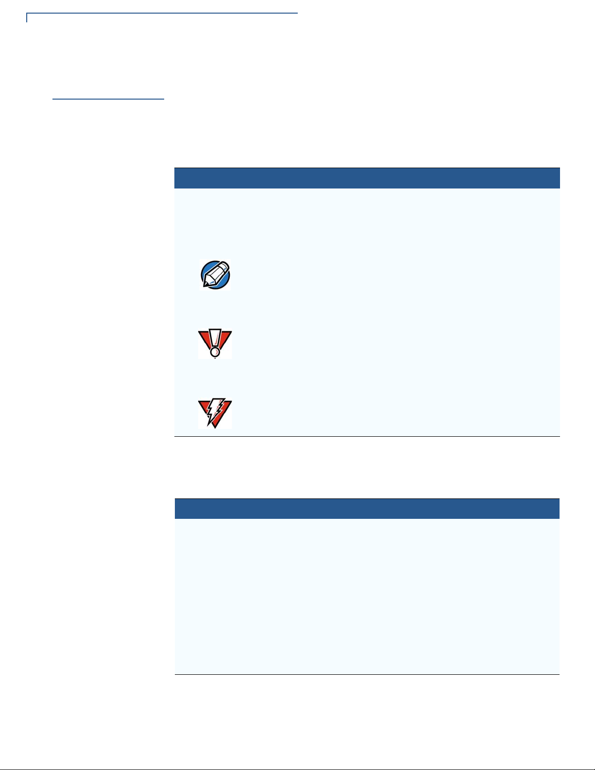
NOTE
CAUTION
WARNING
Conventions and Acronyms
Conventions and
Acronyms
Document
Conventions
This section describes the conventions and acronyms used in this guide.
Various conventions are used to help you quickly identify special formatting.
Table 1 describes these conventions and provides examples of their use.
Table 1 Document Conventions
Convention Meaning Example
Blue
Text in blue indicates terms that
are cross referenced.
The pencil icon is used to
highlight important information.
The caution symbol indicates
possible hardware or software
failure, or loss of data.
See Conventions and
Acronyms.
If exchanging cables use a
Verifone-approved cable.
Avoid placing metallic objects at
the front of the card reader.
Acronym Definitions
The lightning symbol is used as
a warning when bodily injury
might occur.
For safety, do not string cables
or cords across a walkway.
Various acronyms are used in place of full definition. Table 2 represents acronyms
and their definitions.
Table 2 Acronym Definitions
Acronym Definitions
CTLS Contactless
EMV Europay, MasterCard and Visa
IC Integrated Circuit
LED Light-Emitting Diode
MRA Merchandise Return Authorization
NFC Near Field Communication
RF Radio Frequency
RJ45 Registered Jack 45 Modular Connector
Single CI Single Contactless Interface
SMA SubMiniature version A connector
6 K450 INSTALLATION GUIDE
Page 7
Device Overview
CHAPTER 1
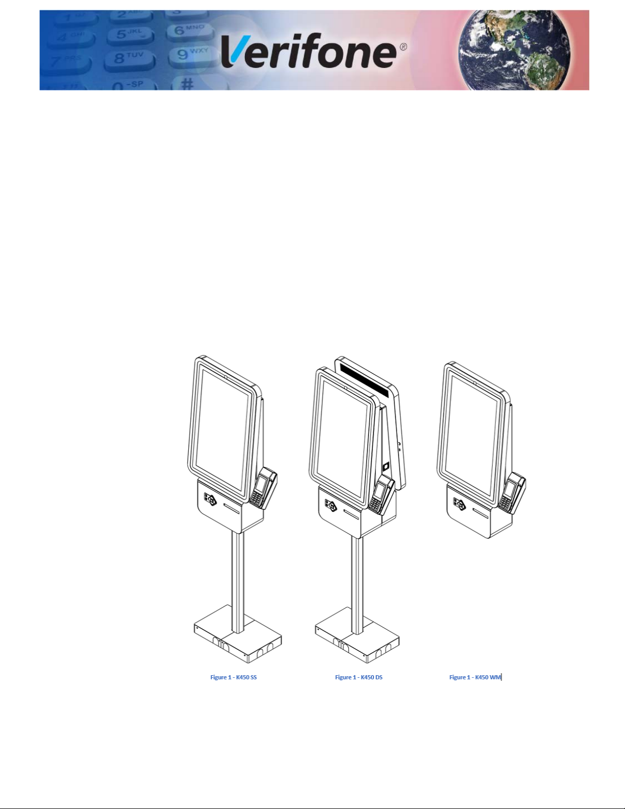
The K450's beautiful design and large 27" screen creates a powerful magnetic
customer attraction. Bring your brand to life with rich graphics that are eyecatching and dynamically disrupt traffic patterns. Its modular design can be
configured to meet all of your self-service needs across your organization. It can
be mounted as a floor standing kiosk with wiring routed through the floor or above
the floor, or from the ceiling. It can also be mounted to a wall and is available with
or without a receipt printer. And ADA and DDA compliance helps provide great
experiences for customers of all needs. Your kiosk may have come preconfigured
with additional devices such as a barcode scanner and Verifone payment device.
Your K450 easily and securely routes data and power lines, keeping sensitive
components securely locked inside an all-metal chassis.
Figure 1- K450 Unit
K450 INSTALLATION GUIDE 7
Page 8

DEVICE OVERVIEW
Features and Benefits
Features and
Benefits
Exceptional Ease of
Use
Following are the features and benefits of K450 device:
The following features of the device simplifies transactions in various
environments:
• K450 device is the most modern, slim and yet fully featured kiosk currently
available.
• Can be ordered as a single-sided or dual-sided pole mountable; or, as wall
mountable.
• Highly configurable with multiple options for payment devices and other
accessories.
• A small, sleek module below the main display has accessibility to keypads and
RFID scanners.
• An optional larger module supports larger devices such as printers and insert
card readers.
• Access to internal components is simple and toolless.
• Dual-sided units support fully independent operations with support for two
PCs, two payment devices and duplicate accessory devices.
Performance and
Durability
Security
• Kiosk are packaged with necessary power cords and cables to operate in
different countries.
• Displays are 27" high definition, capacitive touchscreens for highly detailed,
responsive user interfaces.
• Supports multiple ethernet lines as well as optional Wi-Fi.
• Designed for Verifone payment devices and services for secure transactions.
• Powerful processing capabilities including the latest Dell and Lenovo PCs with
Intel i5 or i7 processor, solid-state drives, expandable memory options, Wi-Fi
and cellular data.
• Windows, Linux and Android support available.
• Optional external omni-directional Wi-Fi for reliable, long-range wireless
connectivity.
• Separate ethernet connectivity to payment device and PC.
• Certified by UL, CE and NOM for safe and reliable operation.
• Power and data are securely routed through the bottom pole for above or
ground wiring or through the top pole for drop-ceiling installations.
8 K450 INSTALLATION GUIDE
• Main cabinet is secured with an industrial cam lock along with security key.
• Tamper-resistant and anti-vandalism enclosure and components.
Page 9

DEVICE OVERVIEW
Features and Benefits
Connectivity
• Supports up to six internal USB devices.
• Single-sided pole and wall mount units support 2 ethernet connections; dual-
sided pole mount unit supports 4 ethernet connections.
• Power and ground from facilities main through either the bottom or top poles.
• Optional wireless connectivity.
NSTALLATION GUIDE 9
K450 I
Page 10

DEVICE OVERVIEW
Features and Benefits
THIS PAGE IS INTENTIONALLY LEFT BLANK
10 K450 INSTALLATION GUIDE
Page 11

Specifications
CHAPTER 2
K450
Specifications
This chapter lists the power requirements and other specifications of
the K450 unit.
Standard Specifications
Processor Intel i5 or i7, Qualcomm Snapdragon
Memory 8GB or 16GB
Storage 128GB or 256GB SSD
OS Windows 10, Linux, Chrome OS, Android
Display 27" High Definition Capacitive Touchscreen (PCAP)
Input Power 120V - 240V AC, 50/60 Hz
Current Rating 2A, 4A Dual Sided
Accessibility Storm Interface AudioNav Keypad, ADA compliant, 6-key
navigation, audio jack, illuminated
Cooling Two system fans and vented enclosure
Environment Operating temperature: 5°C to 30°C (40°F to 85°F)
Storage temperature: -30°C to 60°C (-20°F to 140°F)
Operating humidity: 20% to 80% (non-condensing)
Storage humidity: 5% to 90% (non-condensing)
Altitude: up to 2000m (6,500ft)
Optional Specifications
Payment Verifone P200/P400
Verifone M400
Verifone M915/M925
Printer 80mm receipt printer
Barcode Scanner Printed or digital barcodes
Contactless RFID reader
K450 INSTALLATION GUIDE 11
Page 12
SPECIFICATIONS
K450 Specifications
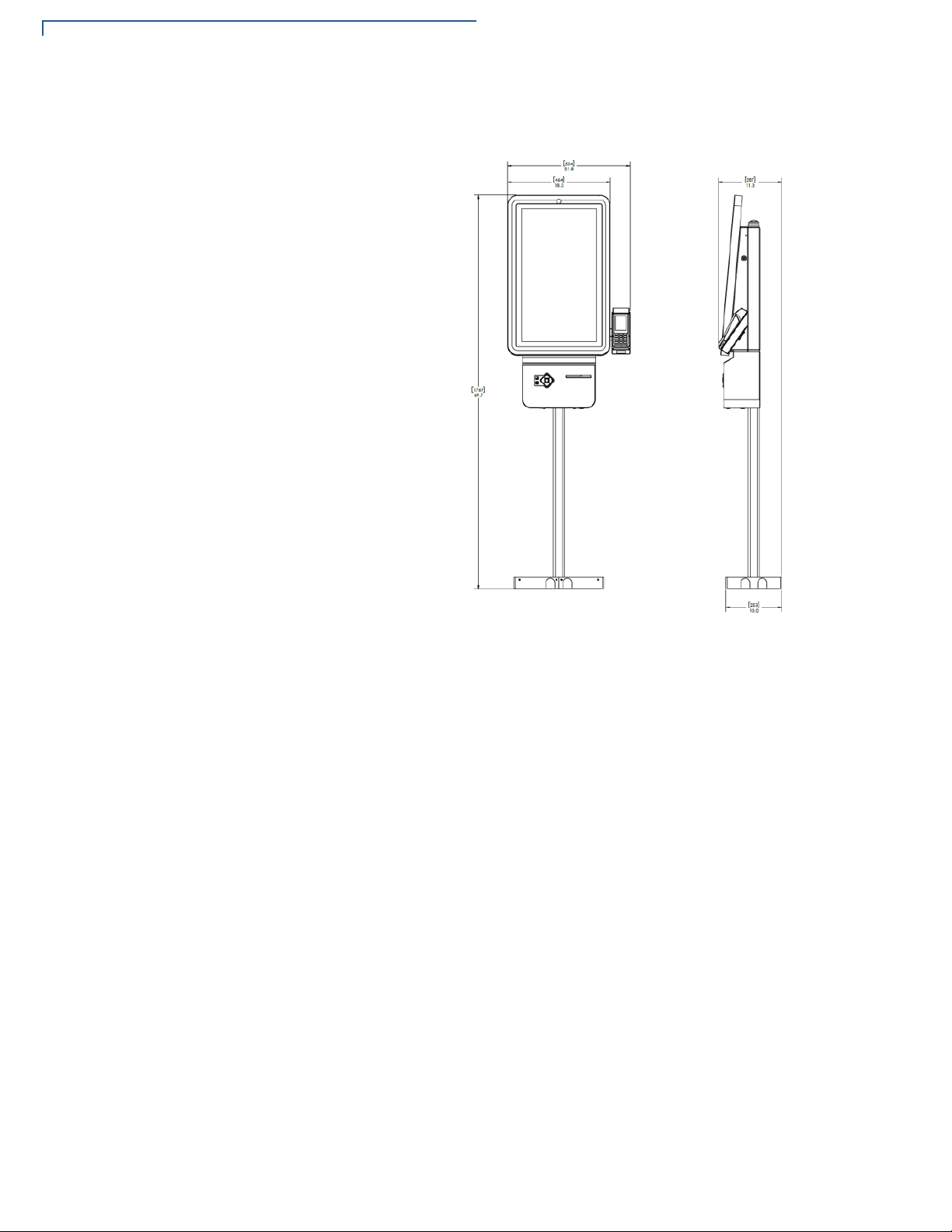
K450 Specifications
Figure 2 K450 SS - Single-Side Pole Mounted
12 K450 INSTALLATION GUIDE
Page 13

SPECIFICATIONS
K450 Specifications
Figure 3 K450 DS - Dual-Sided Pole Mount
Figure 4 K450 WM - Wall Mountable
NSTALLATION GUIDE 13
K450 I
Page 14

SPECIFICATIONS
K450 Specifications
THIS PAGE IS INTENTIONALLY LEFT BLANK
14 K450 INSTALLATION GUIDE
Page 15

Setup
CHAPTER 3
This chapter describes the setup procedure for the K450 in the following sections:
• K450 Installation Safety Instructions
• Inside the Shipping Carton
• Installing K450
K450 Installation
Safety
Instructions
Do not attempt to install this product until all the instructions and warnings have
been read and properly understood.
1 Please check carefully to make sure there are no missing or defective parts -
defective parts must never be used.
2 Verifone is not liable or responsible for damage or injury caused by improper
installation, improper use or failure to observe these safety instructions. In
such cases warranty might get void.
Product Location
1 When determining location, ensure that all access doors and panels are
accessible and have enough room to fully open or remove. Ensure that users
can comfortably walk up to and use the kiosk without obstructions.
2 Do not install the kiosk near electrical or explosive hazards or where there are
falling objects else excessive dust and debris will get collected on the kiosk.
3 Do not operate or service the unit unless it is securely mounted to a fixed
surface or stable structure. Failure to mount securely can cause injury or
damage to the kiosk.
Floor Mounting
1 Please ensure to install K450 unit on a suitable, hard, stable floor or surface.
2 K450 unit must be secured to the surface with provided anchor bolts or other
suitable anchors for its intended use. Notify Verifone if you have questions
about your floor or mounting hardware.
Wall Mounting
1 Please ensure to install K450 unit on a suitable wall.
K450 INSTALLATION GUIDE 15
Page 16

SETUP
K450 Installation Safety Instructions
2 If you install this product on drywall then it must be securely fixed to a wooden
stud, concrete block or any other permanent structure behind the drywall
board. Installing on drywall boards alone will not support the weight of K450
equipment.
3 When drilling holes in walls it is essential to avoid contact with electrical cables
and water or gas pipes contained within. Use of good quality live wire detector
and hidden object locator is recommended.
Hazard limitation
It is recommended to periodically inspect the product and its fixing points to
ensure that safety is maintained.
LCD
The response time, brightness and colors of K450 unit may be affected by the
ambient temperature.
1 Tiny spots (dark or luminescent) may appear on the display due to the liquid
crystal characteristics.
2 There are variations in brightness and colors on each unit.
3 Cold cathode tubes are incorporated into the LCD display for backlights.
Optical properties (brightness, irregular colors, etc.) may change in a low
temperature environment or over the time of operation.
Periodic Inspection Periodically inspect the terminal for possible tampering. Signs of tampering
include:
• Wires protruding out of the device.
• Foreign objects inserted into the smart card slot or magnetic stripe slot.
• Any bumps in the casing below the mag stripe slot and any noticeable
additional mag stripe head from the side.
• Signs of damage to the tamper-evident labels.
• A Tamper Warning message on the device display.
• If any device is found to have been tampered with, please remove it from the
service immediately. Keep it available for potential forensics investigation and
notify your company security officer and your local Verifone representative or
service provider. To contact Verifone, please see Verifone Service and
Support.
16 K450 INSTALLATION GUIDE
Page 17

SETUP
WARNING
Inside the Shipping Carton
Inside the
Shipping Carton
To unpack the
shipping carton
Open the shipping carton and carefully inspect its contents for possible tampering
or shipping damage. The device is a secure product. Tampering causes it to
cease to function or to operate in an unsecured manner.
To unpack the shipping carton:
1 Carefully inspect the shipping carton and its contents for possible tampering or
damage.
2 Validate the authenticity of the sender by verifying the shipping tracking
number and other information located on the product order paperwork.
3 Remove and inspect the contents of the shipping carton. The device ships in
multiple configurations. The carton may include all or any of the following:
• Main kiosk cabinet with touchscreen door assembly(s).
• Single-sided and dual-sided units will additionally contain an attached
base pole assembly, two (2) base covers.
• Wall mounted units will include a wall mount bracket and mounting
hardware.
• Hardware Kit.
• Electrical cover(s).
• Your kiosk may have been preconfigured with optional components.
Refer to your sales order or agreement for additional components and
accessories.
4 Remove all plastic wrapping from the device and the components.
5 Remove the clear protective film from the display.
6 Inspect the terminal for possible tampering; see how to identify signs of
tampering in section Periodic Inspection.
7 Save the shipping carton and packing material for future repacking or moving
of the device.
Do not use a tampered or a damaged unit. The device comes equipped with
tamper-evident labels. If a label or component appears damaged, please notify
the shipping company and your Verifone service provider immediately.
NSTALLATION GUIDE 17
K450 I
Page 18

SETUP
Installing K450
Installing K450
Figure 5- K450 Unit
Installing Tools and Materials
• Adjustable Wrench
• Security Hex Key (Provided)
• Small Open-End Wrenches
• Set of Allen Wrenches, Ball End
• Small Socket Set
• Needle Nose Pliers
• #1 and #2 Phillips Screwdrivers
• Wire Strippers
• Drill, Bit Set, Associated Attachments
• 3/8" Anchor Bolts (Minimum QTY 4)
• Anchor Bolt Installation Tools
• Cable Ties
Stability
18 K450 INSTALLATION GUIDE
Kiosk must be securely bolted to the floor or wall in accordance with mounting
instructions contained within this guide. Do not attempt to open or work inside the
kiosk unless kiosk has been securely mounted. If needing to operate the kiosk
Page 19

Installing K450
before installation or in a laboratory or other temporary location, an optional
stability plate is available.
SETUP
Field Wiring
Disconnect Device
Circuit Protection
Floor Mounting
1 All lines are routed inside the building within a grounded conduit
(recommended ½" diameter terminated by a ¾" Romex connector).
2 Incoming power lines are type TN-C with three conductors (hot, neutral and
ground).
3 All field wiring shall be in accordance with the National Electrical Code (NEC).
A readily accessible disconnect device shall be incorporated into the building
installation wiring.
1 Circuit Type: Branch Circuit Protection
2 Input Voltage: 120 - 240V AC, 50 - 60 Hz
3 Max Current: 2A - Single-Sided and Wall Mount
4A - Dual-Sided
1 Anchor bolts provided are intended for concrete. Concrete flooring must meet
commercial building standards. Verify for your local State building code.
2 Mark the floor corresponding to the anchor slots on the kiosk.
3 Drill 3/8" anchor bolt holes (4 minimum) to support anchor bolts into the floor
at least 4"-5" deep.
4 Install anchors into floor and verify that they are tight and have not damaged
the floor.
NSTALLATION GUIDE 19
K450 I
Page 20

SETUP
CAUTION
WARNING
Installing K450
5 Lift kiosk and align slots in base to anchors. Carefully lower the kiosk onto
anchor bolts and secure with washers and nuts. Ensure nuts are properly
tightened.
Power and Data
Lines from Floor
1 If power and data lines come from the ceiling, skip to next section.
2 Start routing wires at the pedestal's base.
3 If the wires come up from the floor underneath the base, run the wires through
the provided 3.5" x 1.5" cutouts. Run power lines through one cutout and data
lines through the other (check labels on base).
4 If the wires run through a conduit above the floor, use the existing routing
holes on the sides of the base. Use different holes for power and data lines.
There is a divider inside the pedestal pole to separate power and data lines.
DO NOT run power and data through the same side.
Run two data lines up through the pedestal pole on the data side of the divider.
With electrical cover removed, there is exposure to electrical hazards such as
bare electrical wire and terminals. Only personnel with proper training and
experience should remove electrical cover.
20 K450 INSTALLATION GUIDE
Page 21

SETUP
Installing K450
Base Cover
Installation
• Green (Ground) to Ground Nut
• Black (Hot) to Black (Hot)
• White (Neutral) to White (Neutral)
1 Remove screws from base.
2 Place covers on base and ensure center tabs interlock.
NSTALLATION GUIDE 21
K450 I
Page 22

SETUP
Installing K450
3 Reinsert screws and tighten.
Top Pole Installation
Install the top pole onto the top of the kiosk and secure the bolts in place using
supplied nut hardware.
22 K450 INSTALLATION GUIDE
Page 23

Top Pole Pa rts
SETUP
Installing K450
Top Pole Extension
If ceiling is higher than 10 feet, a Top Pole Extension is required.
STEP 1: REMOVE TOP POLE
DO NOT drill holes near electrical wires. Disconnect power lines from kiosk before
installing top pole extension.
The top pole extension is attached to the top pole and thread-forming screws.
These screws require pre-drilled holes. If the top pole doesn't have pre-drilled
holes at the top of the pole, they need to be created.
1 Unpack the top pole extension. It comes assembled with mounting brackets
and hardware as shown in Figure 2.
NSTALLATION GUIDE 23
K450 I
Page 24

SETUP
Installing K450
2 Align the inside divider plate in the top pole extension with the divider in the
top pole with the "POWER ONLY" labels on the same side. Slide the top pole
extension onto the top pole until it stops.
3 Attach top pole extension to top pole with included thread-forming screws.
Align holes in extension to holes in top pole and secure with screws.
4 Turn the poles over and install screws to remaining side.
STEP 2: CONNECT POWER + DATA LINES
24 K450 INSTALLATION GUIDE
Run power and data lines through poles. If lines run into interference at the
junction of the two poles, remove screws and slide top pole extension away from
top pole.
STEP 3: SECURE TOP POLE EXTENSION TO CEILING
Use the provided ceiling mounting bracket or other sufficient method to secure the
top of the extension to the facilities ceiling structure.
Page 25

Installing K450
CAUTION
WARNING
Power & Data Lines from Ceiling
1 If power and data lines come from the ceiling, see previous page.
2 Start at the top of the top pole.
3 Guide power cables down through the top pole.
There is a divider inside the top pole to separate power and data lines. DO NOT
run power and data through the same side.
4 Remove top cover and connect hot and neutral power lines to terminal block.
Connect ground wire to grounding stud.
5 Run two data lines down through the top pole on the data side of the divider.
With electrical cover removed, there is exposure to electrical hazards such as
bare electrical wire and terminals. Only personnel with proper training and
experience should remove electrical cover.
SETUP
NSTALLATION GUIDE 25
K450 I
Page 26

SETUP
Installing K450
Wall Mounting
26 K450 INSTALLATION GUIDE
Hang the kiosk on the bracket and secure with ¼-20 nuts and washers
Page 27

SETUP
WARNING
Installing K450
Operation
Opening Kiosk
Open monitor panel by unlocking side of the cabinet, Figure 5, and pulling the
display forward firmly.
ELECTRICAL HAZARD RISK - Inside of kiosk contains power wires and
electronic devices. Only authorized personnel should open kiosk. Take
necessary precautions when working with electrical equipment.
NSTALLATION GUIDE 27
K450 I
Page 28

SETUP
Installing K450
Figure 6 Cabinet Lock
Removing Cabinet
Rear Panel
1 A rear service panel provides additional access to internal components and
wiring. Only authorized personnel should remove panel.
2 To remove:
• Open monitor panel. (See Opening Kiosk).
• From inside the cabinet, pull the pin on the left of the cabinet.
• Lift the rear panel straight up until it stops and then pull the panel straight
back.
28 K450 INSTALLATION GUIDE
Page 29

SETUP
Installing K450
NSTALLATION GUIDE 29
K450 I
Page 30

SETUP
NOTE
Installing K450
Connecting Data
Line to Payment
Device
1 Connect one data line to the dongle of the payment device. Secure extra cable
with cable ties.
The payment device hub will be located in the cabinet. Connect the data line to
the available network jack on the hub.
2 Connect other data line to the network port of the computer. Secure extra
cable with cable ties.
30 K450 INSTALLATION GUIDE
Page 31

SETUP
Installing K450
Connecting Devices
1 Connect power to the touchscreen monitor with its provided power adapter
located inside the cabinet.
2 Connect power to the computer with its power adapter located inside the
cabinet.
3 Connect the USB cable from the ADA keypad device to the computer.
4 Secure all excess cables with cable ties.
Turning on Kiosk
Replacing Printer
Paper
1 Open monitor panel. (See Opening Kiosk above).
2 Turn on power strip using its power button (left image).
3 Turn on computer by pushing button on front (right image).
1 Open the component door by pushing the button on the bottom of the printer
cabinet.
2 Press the release button on the printer to open the printer door.
3 Replace paper and close printer door.
4 Close component door until lock fully engages.
NSTALLATION GUIDE 31
K450 I
Page 32

SETUP
Installing K450
THIS PAGE IS INTENTIONALLY LEFT BLANK
32 K450 INSTALLATION GUIDE
Page 33

Maintenance and Cleaning
CAUTION
Your self-serve kiosk is a product of superior design and craftsmanship and
should be treated with care. It has no user-serviceable parts.
The following suggestions will help you protect your warranty coverage.
• Do not store the device in hot areas. High temperatures can shorten the life of
electronic devices, damage batteries and warp or melt certain plastics.
• Do not store the device in cold areas. When the device returns to its normal
temperature, moisture can form inside the device and damage electronic
circuit boards.
• Do not drop, knock, or shake the device. Rough handling can break internal
circuit boards and fine mechanics.
• Do not use harsh chemicals, cleaning solvents, or strong detergents to clean
the device. Use a wet soapy cloth to clean the device surfaces.
CHAPTER 4
Additional
Safety
Information
Surface Cleaning
Potentially
Explosive
Environments
These suggestions apply equally to your contactless device, or any of its
attachments or accessories. If your device is not working properly, take it to the
nearest Verifone-authorized service provider for servicing or replacement.
The following is additional information for your safety in using this device.
To clean the device, use a clean cloth slightly damped with water and a drop or
two of mild soap. For stubborn stains, use alcohol or an alcohol-based cleaner.
Do not spray water or chemicals directly on the device. Spray liquids onto a cloth
and then apply to kiosk surfaces.
When using the device in areas with potential risk of explosion, such as petrol
stations, follow the advice of all signs and instructions. If there is a leak, then do
not use this device.
K450 INSTALLATION GUIDE 33
Page 34

MAINTENANCE AND CLEANING
Additional Safety Information
THIS PAGE IS INTENTIONALLY LEFT BLANK
34 K450 INSTALLATION GUIDE
Page 35

Verifone Service and Support
NOTE
Contact your local Verifone representative or service provider for any problems on
your terminal.
For product service and repair information:
• USA – Verifone Service and Support Group, 1-800-Verifone (837-4366)
• Monday - Friday, 8 A.M. - 8 P.M., Eastern time
• International – Contact your Verifone representative
CHAPTER 5
Returning a
Device for
Service
You must obtain a Merchandise Return Authorization (MRA) number before
returning the terminal to Verifone. The following procedure describes how to
return one or more terminals for repair or replacement (U.S. customers only).
For international customers, please contact your local Verifone representative for
assistance with your service, return, or replacement.
1 Get the following information from the printed labels at the back of each K450
to be returned:
• Product ID, including the model and part number. For example, “K450” and
“M500-XXX-XXX-XXX.”
• Serial number (S/N nnn-nnn-nnn)
2 Obtain the MRA number(s) by completing one of the following:
a Call Verifone toll-free within the United States at 1-800-Verifone and follow
the automated menu options.
• Select the MRA option from the automated message. The MRA
department is open Monday to Friday, 8 A.M.– 8 P.M., Eastern Time.
• Give the MRA representative the information you gathered in Step 1.
• Complete the Inquiry Contact Form at https://www.verifone.com/en/us/
contact-us.
• Address the Subject box to “Verifone MRA Dept.”
K450 INSTALLATION GUIDE 35
Page 36

VERIFONE SERVICE AND SUPPORT
NOTE
Accessories and Documentation
• Reference the model and part number in the Note box.
One MRA number must be issued for each K450 you return to Verifone, even if
you are returning several of the same model.
3 Describe the problem(s).
4 Provide the shipping address where the repaired or replacement unit must be
returned.
5 Keep a record of the following items:
• Assigned MRA number(s).
• Verifone serial number assigned to the K450 you are returning for service
or repair (device serial numbers are located at the back of the unit.)
• Shipping documentation, such as air bill numbers used to trace the
shipment.
Accessories and
Documentation
Documentation
• Model(s) returned (model numbers are located on the Verifone label at the
back of the K450).
Verifone produces the following accessories and documentation for the
K450. When ordering, please take note of the part number.
• Verifone online store www.estore.verifone.com
• USA – Verifone Customer Development Center, 800-Verifone (837-4366),
Monday - Friday, 7 A.M. - 8 P.M., Eastern time
• International – Contact your Verifone representative
K450 Certifications and Regulations VPN DOC500-010-EN
K450 SS DS Quick Installation Guide VPN DOC500-011-EN
K450 WM Quick Installation Guide VPN DOC500-012-EN
36 K450 INSTALLATION GUIDE
Page 37

CHAPTER 6
NOTE
CAUTION
Troubleshooting
Guidelines
The troubleshooting guidelines provided in the following section are included to
assist you to successfully install and configure your K450 Kiosk. If you have
problems operating your K450 Kiosk, please read through these troubleshooting
examples.
If the problem persists even after performing the outlined guidelines or if the
problem is not described below, contact your local Verifone representative for
assistance. Typical examples of malfunction you may encounter while operating
your K450 Kiosk and steps you can take to resolve them are listed.
The K450 Kiosk comes equipped with tamper-evident labels. The K450 contains
no user serviceable parts. Do not, under any circumstances, attempt to
disassemble the unit. Perform only those adjustments or repairs specified in this
guide. For all other services, contact your local Verifone service provider. Service
conducted by parties other than authorized Verifone representatives may void any
warranty.
Using an incorrectly rated power source can damage the unit or cause it to
malfunction.
Device Does Not
Peripheral
Work
See Specifications for power source information.
If any peripheral device (PIN pad or smart card reader) does not work properly:
• Check the power cord connection to the peripheral device.
• Check for proper grounding connections.
• Check that the device connected to the proper port has power and is
functioning properly. If possible, perform a self-test on the device in question.
• The cable connecting the optional device to the PC port may be defective. Try
a different serial cable.
• If the problem persists, contact your local Verifone representative.
K450 INSTALLATION GUIDE 37
Page 38

TROUBLESHOOTING GUIDELINES
Peripheral Device Does Not Work
THIS PAGE IS INTENTIONALLY LEFT BLANK
38 K450 INSTALLATION GUIDE
Page 39

Caution and Warning Messages
APPENDIX A
K450 Caution
and Warning
Messages
Products with UL/cUL Listed should include French translations of Caution and
Warning notices. The following table shows all notices found in the document,
their location and the equivalent French translations.
Table 3 Caution and Warning Messages
Notice Chapter Page English Text French Text
Warning Setup page 9 For safety, do not string cables
or cords from your installation
cabinet or housing across a
walkway.
Warning Setup page 10 Do not use a unit that has been
damaged.
If a label or component
appears damaged, please
notify the shipping company
and your Verifone service
provider immediately.
Caution Setup page 15 Observe standard precautions
in handling electrostatically
sensitive devices. Electrostatic
discharges can damage the
equipment. Verifone
recommends using a grounded
anti-static wrist strap.
Caution Setup page 18 Using an incorrectly rated
power source can damage the
unit or cause it to malfunction.
Pour la sécurité, ne sont pas des câbles à
cordes ou des cordons de votre armoire
d'installation ou de logement à travers
une passerelle.
Ne pas utiliser un appareil qui a été
endommagé.
Si une étiquette ou d'un composant
semble endommagé, se il vous plaît
aviser la compagnie de navigation et
votre fournisseur de services Verifone
immédiatement.
Observer les précautions standard dans
le traitement de dispositifs sensibles aux
décharges électrostatiques. Les
décharges électrostatiques peuvent
endommager l'équipement. Verifone
recommande d'utiliser un bracelet anti statique à la terre.
L'utilisation d'une source alimentation mal
classé peut endommager l'appareil ou
provoquer un dysfonctionnement.
Caution Maintenance
and
Cleaning
Caution Troubleshoot
ing
See Specifications for power
supply information.
page 23 Never use thinner,
trichloroethylene, or ketone
based solvents – they can
deteriorate plastic or rubber
parts.
page 29 Using an incorrectly rated
power supply can damage the
unit or cause it to malfunction.
See Specifications for power
supply information.
Voir les caractéristiques de l'information
d'alimentation.
Ne jamais utiliser de diluant, le
trichloréthylène ou des solvants à base
de cétone - ils peuvent détériorer les
pièces en plastique ou en caoutchouc.
L'utilisation d'une alimentation mal classé
peut endommager l'appareil ou provoquer
un dysfonctionnement.
Voir les caractéristiques de l'information
d'alimentation.
K450 INSTALLATION GUIDE 39
Page 40

Verifone, Inc.
1-800-Verifone
www.verifone.com
K450
Installation Guide
Verifone Part Number DOC500-009-EN-A, Revision A
 Loading...