

Page 1

H5000
Installation Instructions
2
ABC
5
JKL
8
0
*
#
TUV
7
PQRS
4
GHI
1
Page 2

Page 3

Verifone GmbH
Konrad-Zuse-Straße 19–21
36251 Bad Hersfeld
Germany
info-germany@verifone.com
www.verifone.de
WEEE-Reg.-Nr. DE 58713050
© 2016 Verifone Corporation, all rights reserved. Verifone and the Verifone logo are registered trademarks of Verifone Corporation. All other products or services which are referred
to in this document, are trademarks, service marks, registered trademarks or registered
service marks of the corresponding owners.
Verifone does not grant tacit warranties for commercial qualities and suitability for a
certain intended purpose.
Verifone assumes no liability for errors or consequential damages which occur as a result
of the features, performance and use of this documentation. This documentation contains
copyright protected information.
This documentation may not be photocopied, duplicated, translated or recorded on data
carriers, neither as a whole nor in parts or excerpts, without the prior approval from
Verifone.
Changes in this documentation as well as all rights reserved.
Technical changes reserved. October 2016 DOC450-005-EN-A Rev. A00
Page 4

4 Installation Instructions H5000
Inhalt
1 Introduction ..............................................................................................................6
1.1 Symbols used .............................................................................................................6
1.2 References for installation instructions .....................................................................6
1.3 Notes on service ........................................................................................................6
1.4 Terms and abbreviations used ...................................................................................7
2 Security .....................................................................................................................9
2.1 Device security ...........................................................................................................9
2.2 Transaction security .................................................................................................11
3 Product description ...............................................................................................13
3.1 Overview ..................................................................................................................13
3.2 Connections and card slots .....................................................................................15
3.3 LED displays ............................................................................................................16
3.4 Function keys ...........................................................................................................17
3.5 Display with touchscreen functionality .....................................................................17
4 Operating the device ..............................................................................................28
4.1 Switching on / off ......................................................................................................28
4.2 Inserting the card .....................................................................................................29
4.3 Laying the card on the reader ..................................................................................29
4.4 Calling up functions directly .....................................................................................30
4.5 Enter digits, text and special characters ..................................................................30
5 Preparing to take the device into operation .......................................................31
5.1 Insert / change merchant card .................................................................................32
5.2 Connecting the device ..............................................................................................35
5.3 Inserting the paper roll .............................................................................................40
6 Taking the device into operation ..........................................................................41
7 Diagnosis ................................................................................................................47
7.1 Extended diagnosis ..................................................................................................47
8 Cleaning and maintenance ....................................................................................48
9 Security seal ...........................................................................................................49
Page 5

Installation Instructions H5000 5
10 Technical eata .........................................................................................................51
10.1 H5000 .......................................................................................................................51
10.2 Replacement paper roll (thermal paper) ..................................................................52
Page 6

6 Installation Instructions H5000
Introduction
1 Introduction
1.1 Symbols used
CAUTION
Warning, which the user must heed to guarantee safe
operation of the device and safety of persons and property.
i
A such marked text contains useful information and tips
for the safe use of the device.
► Here, you are requested to do something.
1.2 References for installation instructions
Target group These Installation Instructions are aimed at users and
administrators of the device.
Subject The Installation Instructions describe the installation and
handling of the device.
Function These Installation Instructions provide the user with the
necessary knowledge about function, installation,
operation, maintenance and disposal of the device.
The Installation Instructions contain all necessary
information for a safe use and give tips about possible
error causes and their rectication.
1.3 Notes on service
Hotline If you have questions about the technology, operation and
function of the device, please contact the hotline of your
service provider
Page 7

Installation Instructions H5000 7
Introduction
1.4 Terms and abbreviations used
CUP China Union Pay
DHCP Dynamic Host Conguration Protocol
ELV/EDDS Electronic Direct Debit Scheme
EMV Europay, MasterCard, VISA
The EMV standard was dened by the international card organisations
Europay, MasterCard and Visa for the safe, chip-supported payment
transactions with debit and credit cards. EMV enables safe communication
between chip cards and devices.
Gc Girocard
Girocard girocard is the superordinate and neutral framework of the German credit
industry for the two debit card payment systems electronic cash in trade
(Point of Sale, POS) and the German ATM system.
Girogo girogo is a contactless payment function of the German credit industry.
girogo is based on the Prepaid principle.
Before paying, an amount (max. 200 Euro) must be loaded on the card.
GKK/GCC Gift customer card
ISDN Integrated Services Digital Network
LAN Local Area Network
MSN Multiple Subscriber Number
NFC Near Field Communication
The NFC technology is used to process contactless payment types such
as, e.g. girogo, PayPass und payWave. With the contactless payment,
customers can pay small amounts contactless without inserting the card,
without entering a PIN and without signature.
Ofine With a card payment a connection is not established between the device
and the network operator computer. Payment is stored in the device and
transferred to the network operator later.
Online With a card payment, a connection is established between the device and
the network operator computer and the payment is authorised.
Page 8

8 Installation Instructions H5000
Introduction
PayPass PayPass is the contactless payment function of the MasterCard.
payWave payWave is the contactless payment function of the Visa card.
PIN Personal Identication Number
Secret number to identify the cardowner
PSTN Public Switched Telephone Network (analogue telephone network)
RS232 Recommended Standard 232 (serial interface)
SAM Secure Access Module
SIM Subscriber Identity Module
SSL Secure Sockets Layer
SSL is a hybrid encryption protocol for data transmission via the Internet.
TID Terminal-ID
(Terminal Identication Number)
USB Universal Serial Bus
USB OTG Universal Serial Bus On-The-Go
ZVT/PTT Payment Transaction Terminal
Page 9

Installation Instructions H5000 9
Security
2 Security
2.1 Device security
2.1.1 Standards and guidelines
Conformity The device meets the requirements of the corresponding
guidelines of the European Community, among others the
R&TTE Directive 1999/5/EC, the EMC Directive 2004/108/
EC and the Low Voltage Directive (equipment safety)
2006/95/EC.
i
The Declaration of Conformity is available directly
from Verifone or can be downloaded from the Verifone
homepage.
2.1.2 Requirements concerning the installation site
Environmental conditions ► Install the device on an even surface.
► Choose a location which is as far as possible away from
devices which cause vibrations.
Humidity ► Operate the device only in a dry environment in the
range of 15% to 85% relative humidity without
condensation.
► Pay attention that foreign bodies or liquids do not enter
the inside of the device or the card reader.
Otherwise damages could occur.
Temperature The device is designed for operation within a temperature
range from 0 °C to +45 °C
► Please ensure that the device is not exposed to direct
sunlight or other sources of heat permanently.
The effects of high temperatures can lead to
device damage.
Page 10

10 Installation Instructions H5000
Security
Avoid sources of interference ► Pay attention to an EMC appropriate installation,
maintenance and installation (EMC = Electromagnetic
Compatibility).
Magnetic elds (e.g. from article protection systems) or HF
sources of interference (e.g. from mobile phones, radio
devices, switching power supplies) can interfere with data
transfer and impair operating safety.
► Do not place the device or its connection cables close
to interference sources.
2.1.3 Safe and reliable power supply
Power pack
i
The manufacturer does not assume liability when the
power supply is provided with accessories other than
the supplied power pack!
CAUTION
Danger through use of unsuitable power packs!
The use of unsuitable power packs can lead to overheating
or re. Unsuitable power packs can lead to malfunctions or
damage of the device.
► Operate the device only with the supplied power pack.
Power connection You need a 230 V socket to connect the power pack.
► Keep the power pack uncovered so that the heat
created in the power pack can be dissipated.
► Ensure that the socket is easily accessible so that the
mains plug can be pulled out of the socket immediately
in the case of danger.
Page 11

Installation Instructions H5000 11
Security
2.1.4 Disposal
Disposal of the device According to the EC Directive 2002/96/EC (WEEE
Directive) all electrical and electronic equipment must be
collected separate from the household garbage so that a
proper recycling is guaranteed.
i
Contact your merchant or supplier if you wish to dispose
of the device. He will have further information for you.
Disposal of the lithium
battery
► Dispose of the battery in accordance with the legal
provisions and not with the normal household waste.
2.2 Transaction security
2.2.1 Requirements concerning the installation site
► Set up the device so that a cardholder has the card
reader completely in view after inserting the card.
2.2.2 Capturing the terminal life cycle
The owner of the device is responsible for capturing the
following data via the terminals:
• Type designation and serial number
• Production and delivery date
• Installation sites (chronologic)
• Repair and maintenance
• Taking-out-of-operation and whereabouts
• Loss and possible theft
Page 12

12 Installation Instructions H5000
Security
2.2.3 Conducting regular visual controls
Safety The device corresponds to the prescribed safety standards
and has diverse safety mechanisms. This protection is
effective against interventions in the device and against
“tapping” of the data trafc.
Protection can be lost through externally applied mounting
structures to the device (e.g. by attaching a card reader or
keyboard).
The rules of the regulatory authorities oblige the owner of
the device to instruct the cashiers and to have the cashiers
conduct regular visual inspections.
i
Sensitize your cashiers and have the cashiers conduct
regular visual controls.
Conducting visual controls ► Check the following device elements during the visual
control:
• The keyboard eld for a possible mounting structure on
the original keyboard
• The cared reader for a possible manipulation of the
visible magnetic strip reader head and for mounting
structure of the complete reader
• The safety seal for integrity and the correct seal serial
number
• The device housing for unknown discolorations, cracks
and overwidth joints between the individual device
parts.
Page 13

Installation Instructions H5000 13
Product description
3 Product description
3.1 Overview
2
ABC
5
JKL
8
0
*
#
TUV
7
PQRS
4
GHI
1
1
2
4
6
7
8
5
9
3
1 Printer (optional) 6 PINPad
2 Card reader 7 Function keys
3 Kensington-Lock
device
8 On/Off switch
4 Display with touch-
screen functionality
9 Operating display
5 NFC reader
The H5000 is a card payment terminal with integrated
customer service unit (PINPad), a hybrid card reader for
magnetic strips and chip as well as an NFC reader.
Communication Depending on the model, communication can be carried
out via the analogue telephone network, ISDN or LAN for
online transactions.
Page 14

14 Installation Instructions H5000
Product description
PINPad The integrated PINPad allows processing of
PIN-supported payment transactions (PIN Number).
Function keys
The function keys are colour coded and tted with symbols
identiable by touch (see chapter 3.4 Function keys on
page 17).
Printer (optional) The installed thermo-printer prints payment receipts,
diagnosis records and device-specic information.
Card reader The device has a hybrid card reader for magnetic strips
and chip.
This means that all card types can be processed, no
matter whether these are bank customer cards, chip cards
or multifunctional cards with magnetic strip and chip.
NFC reader The NFC antenna installed in the display frame, allows
contactless payment methods (e.g. girogo, PayPass,
payWave). Only cards which support this function can be
processed.
Kensington Lock unit The device has a Kensington Lock unit for a Kensington
Lock cable. With a Kensington Lock cable, a strong steel
cable, you can protect your device against theft.
Display with touchscreen
functionality
The device is mainly operated via the display with
touchscreen functionality.
Softkeys on the display, which are operated with the naked
nger, take over the function of keys. As the user interface
on the touchscreen adapts to the usage situation, you
have direct access to many functions of the device.
In addition to the short keys for calling up functions, the
display shows menu texts and entries (see chapter 3.5
Display with touchscreen functionality on page 17).
Merchant card slot (SAM) There are three slots available to receive Security Access
Modules (SAMs, merchant cards). Merchant cards are
necessary, among other things, when payment is to be
accepted by GeldKarte.
Page 15

Installation Instructions H5000 15
Product description
3.2 Connections and card slots
RS232
LAN
ISDN
DC IN
USB
USB OTG
MicroSD
PSTN
5
4
3
2
1
6
8
7
1 Merchant cards 5 micro-SD card
2 DC IN 9V 6 USB
3 ISDN / PSTN 7 USB OTG
4 LAN 8 RS232
Page 16

16 Installation Instructions H5000
Product description
3.3 LED displays
12
3
LED Status Description
1 Blinking At least one contactless
payment type is activated.
Shines
continuously
The NFC reader is active.
The card can be placed.
Does not shine No contactless payment method
is activated.
2 Shine
simultaneously
The contactless payment was
carried out successfully.
3 Shines Device is switched on.
Doesn’t shine Device is switched off.
Page 17

Installation Instructions H5000 17
Product description
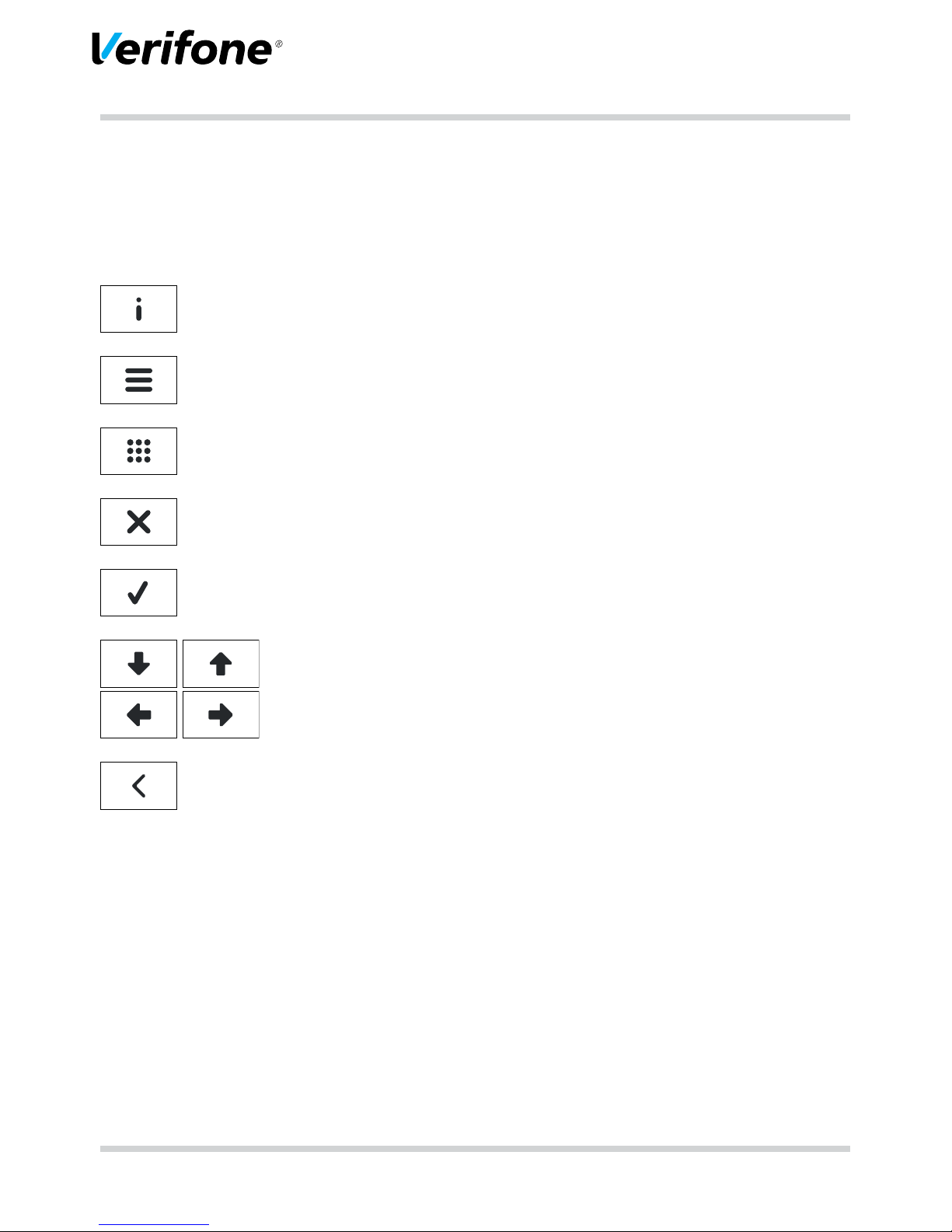
3.4 Function keys
Key Function
• Cancel process
• Jump backwards in menu
• Correct entry
• Delete last entered character
• Delete characters in front of cursor position
• Call up manual entry of credit card data
• Conrm entry
• Start procedure
• Print duplicate of last printed receipt (in basic state)
• Navigation in menu:
– Navigate downwards
– Scroll backwards between individual pages (in the case of several
menu pages)
• Navigation in menu:
– Navigate upwards
– Scroll forwards between individual pages (in the case of several
menu pages)
• In basic state:
– Call up ZVT/PTT function code entry
3.5 Display with touchscreen functionality
CAUTION
The operation with a pen or similar objects can impair the
touchscreen functionality of the display or even damage
the display.
► Operate the display only with the nger
Page 18
18 Installation Instructions H5000
Product description
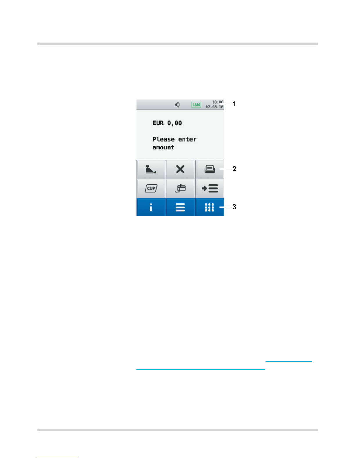
3.5.1 Display in basic state
After switching the device on, the display is shown in the
basic state.
From this dialog, you can call up the following menus via
softkeys (3):
• Main menu
• Transactions
• Information
Further softkeys (2) are arranged on the display to call up
frequently used functions such as, e.g. reconciliation or
reversal directly.
The selection of these softkeys can be adjusted to need
(see Operating Instructions, chapter “Assigning Softkeys”).
Date and time are displayed in the status bar (1). The
status bar also supplies information about the status of
the RDT connection and shows whether the contactless
payment has been activated (see chapter 3.5.5 Symbols
in the status bar of the display on page 22).
Page 19

Installation Instructions H5000 19
Product description
3.5.2 Main menu
You can reach the Main menu from the basic state via the
following softkey:
In the Main menu you can conduct settings on the device,
enter system data, congure payment processes (e.g.
tips, printing receipts) and call off information.
In addition, there are functions available for diagnosis
and service.
Some functions which are called up via the menu
Transactions, can also be reached via the Main menu (e.g.
reconciliation).
You can nd the description of the main menu in the Operating Instructions in the chapter “Main menu.”
Page 20

20 Installation Instructions H5000
Product description
3.5.3 Transactions
From the display in the basic state you can reach the
menu Transactions via the following softkey:
In the menu Transactions you can call up various functions
(see chapter Transactions on page 24).
• Types of payment (e.g. girocard)
• Additional applications (e.g. Prepaid)
• Functions for Administration (e.g. reconciliation)
You can scroll between the individual pages with the
following softkeys:
Or
Page 21

Installation Instructions H5000 21
Product description
3.5.4 Information
From the display in the basic state you can reach the
menu Information via the following softkey:
In the menu Information you can call up frequently used
information and switch off the device or restart it (see
chapter Information on page 26).
Page 22

22 Installation Instructions H5000
Product description
3.5.5 Symbols in the status bar of the display
Symbol Description
LAN connection exists
LAN connection not set up
There is no TCP/IP connection (e.g. cable not plugged)
Secure connection
Non-secured connection
Connection via Modem / ISDN available
Connection via Modem / ISDN not available
Online connection (Modem, ISDN or LAN)
USB connection available
Process under way
At least one contactless payment type activated
Page 23
Installation Instructions H5000 23
Product description
3.5.6 Softkeys on display
Navigation
Softkey Called functions
Information
Main menu
Transactions
Abort process
Jump backwards in menu
Conrm entry
Start procedure
Navigation
Correct entry
Delete last entered character
Delete character in front of cursor position
Call up manual entry of credit card data
Page 24

24 Installation Instructions H5000
Product description
Transactions
Softkey Called functions
Reconciliation
Ofine direct debit
Reversal
Refund
Permission by telephone
Reservation
Tip
Online direct debit
girocard
CUP card
GeldKarte
Prepaid
Page 25

Installation Instructions H5000 25
Product description
Softkey Called functions
Account splitting
Amex Rewards
Payback
TAX
FREE
Tax Free (Global Blue)
GKK/GCC application (Gift Customer Card application)
Diagnosis
Daily sums
Ofine transfer
Page 26

26 Installation Instructions H5000
Product description
Further functions
Softkey Called function
Paper feed
Administration
ZVT/PTT codes
Selection menu
Information
Symbol Called function
Support
Shows the hotline of your service provider
System
Shows the system data of your device
Self test
Checks the device for proper function.
You can nd further information in the Operating Instructions in the chap-
ter “Self test.”
Last transaction
Shows information about the last transaction (e.g. payment, reconciliati-
on).
Calendar
Shows a calendar and the current date.
Page 27
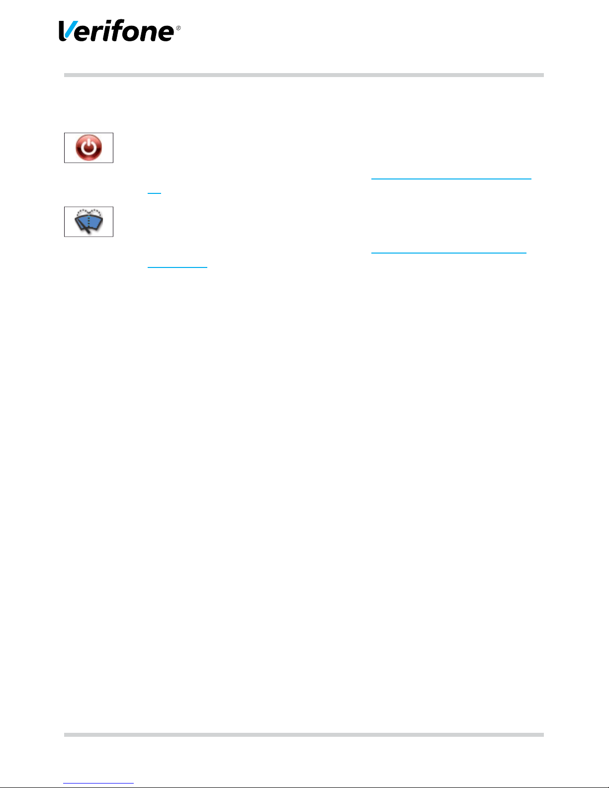
Installation Instructions H5000 27
Product description
Symbol Called function
Switch off / Restart
Calls up the menu Deactivate.
You can nd further information in chapter 4.1 Switching on / off on page
28.
Display cleaning
Activates the cleaning mode of the device.
You can nd further information in chapter 8 Cleaning and maintenance
on page 48.
Page 28

28 Installation Instructions H5000
Operating the device
4 Operating the device
4.1 Switching on / off
4.1.1 Switching on
► Press the On/Off switch on the underside of the device.
A signal sounds.
Power indicator is illuminated.
Keyboard illumination is on.
Operating system of the device is loaded.
As soon as the device is ready for operation, the user
dialog for standard payment processes is displayed.
4.1.2 Switching off
► Press the On/Off switch until the display turns black and
the keyboard illumination switches off.
4.1.3 Switching off / Restarting via softkey
► Select the function Information.
► Select the function Deactivate.
► Select the corresponding function.
– Deactivate and Yes: the device switches off.
– Restart and Yes: The device restarts.
Page 29

Installation Instructions H5000 29
Operating the device
4.2 Inserting the card
2
1
► Insert the swipe card with the magnetic strip (1) facing
back left into the slot from above.
i
Pay attention that the swipe card is inserted with
constant speed. Abrupt changes of speed can lead to
reading errors.
► Insert the chip card with the chip (2) facing the display
into the slot from above.
i
Pay attention that the card is inserted right up to the
stop and is removed only after conclusion of the
transaction or after request shown on the display.
4.3 Laying the card on the reader
2
ABC
5
JKL
1
QZ
1
2
One of the contactless payment methods is activated.
LED (1) is illuminated.
► Hold the card close to the display.
A signal sounds.
All LEDs (1 and 2) are illuminated.
Page 30

30 Installation Instructions H5000
Operating the device
4.4 Calling up functions directly
In the basic state, 6 softkeys are arranged in the lower half
of the display. You can call up frequently used functions,
such as e.g. reconciliation or reversal with these softkeys.
► Press the softkey on the display to call up the function.
i
You can assign the display according to your needs
(see Operating Instructions, chapter “Assigning Softkeys”.
4.5 Enter digits, text and special characters
Digits, text and special characters are entered via the
keyboard or the display. All keys are assigned with several
characters.
You can nd the following characters on one key:
• the digit and letters shown on the key, e.g. "2ABC"
• the corresponding lower case letters, e.g. “abc”
• possible Umlaute, e.g. “Ää” or special characters such
as “ß”.
You can nd further special characters on the key “0“.
► Press the key which shows the desired character, on
the keyboard or on the display.
The selectable characters are displayed.
► Press the key as many times as required until the desi-
red character is marked.
The character is accepted after a short waiting period.
Page 31

Installation Instructions H5000 31
Preparing to take the device into operation
5 Preparing to take the device into operation
CAUTION
Impairment of the device function through dust and
moisture!
► Choose an installation site which is free of dust,
moisture and high humidity.
Necessary equipment You need the following equipment for the installation:
• Standard-Equipment
– H5000 Terminal
– Paper roll
– Power pack
• 230 V socket for power supply
GeldKarte
i
If you wish to accept and conduct payments by the
GeldKarte at the device, you require a valid merchant
card. You can get the merchant card from your bank.
micro-SD card For future applications of the device, a contact for a micro-
SD card is arranged in the connector compartment.
Page 32

32 Installation Instructions H5000
Preparing to take the device into operation
5.1 Insert / change merchant card
Three chip card contacts for merchant cards (SAM slots)
are arranged in the connector compartment of the device
under a cover.
If you wish to process GeldKarten a merchant card must
be inserted into the device rst. You can get the merchant
card from your bank.
i
Merchant cards have a limited validity. Please pay
attention to the expiry date of your merchant card.
CAUTION
Destruction of the chip on the merchant card due to voltage on the device!
► Before inserting the merchant card, separate the device
from the power supply.
Preparing change of the
merchant card
► Conduct a successful reconciliation (see Operating
Instructions, chapter “Reconciliation“).
► Separate the device from the power supply.
► Place the device, operating eld side down, on a clean
non-slip storage surface.
► Remove the cover of the connector compartment:
– Slide the lock of the cover in arrow direction.
– Remove the cover from the connector compartment.
Page 33

Installation Instructions H5000 33
Preparing to take the device into operation
Inserting the merchant card
1
2
► Unlock the cover (2).
► Slide the cover (1) with your ngers in the direction of
the arrow.
► Remove the cover.
CAUTION
Destruction of electrostatically sensitive components
through touching!
► Pay attention to the measures to protect electrostatically
endangered components.
► Avoid touching any of the contacts and the electric
components.
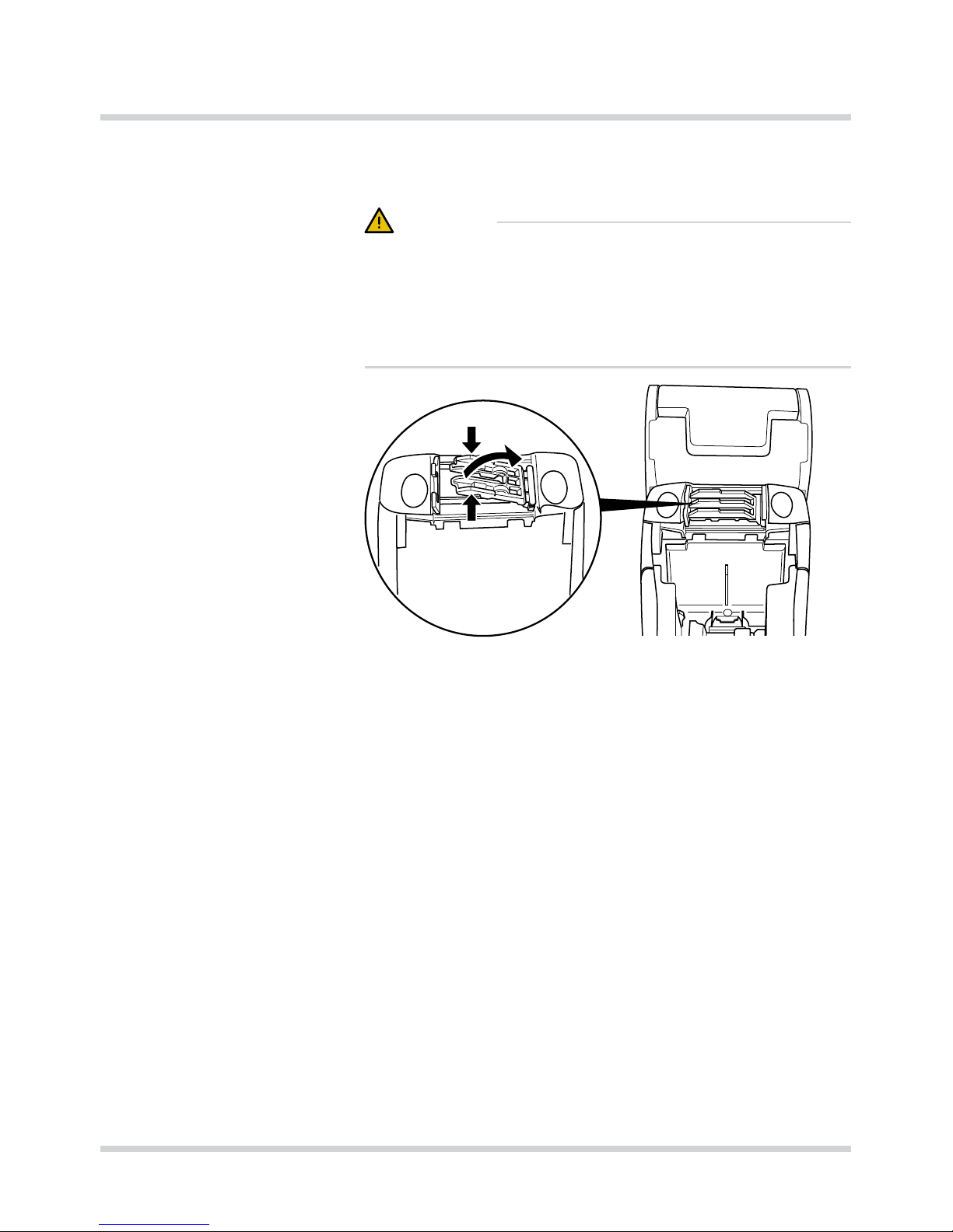
► Open the lock.
► Flip open the card holder.
Page 34

34 Installation Instructions H5000
Preparing to take the device into operation
► Remove any existing merchant card from the card
holder.
21
► Pay attention to the correct alignment when inserting
the merchant card:
– The chip points in the direction of the device (1).
– The slanted edge sits to the left top (2).
► Slide the merchant card up to the stop into the card
holder.
Page 35
Installation Instructions H5000 35
Preparing to take the device into operation
► Close the card holder again.
► Close the lock carefully.
i
The locks of all card holders must be closed.
► Slide the cover of the chip card contacts in until the
cover engages.
► Insert the cover of the connector compartment.
5.2 Connecting the device
CAUTION
Danger of accidents through loose cables!
► Secure all cables through the strain relief and further
corresponding devices, e.g. cable ducts.
Page 36

36 Installation Instructions H5000
Preparing to take the device into operation
5.2.1 Connecting data lines
CAUTION
Malfunctions or damage of the device through operation
with incorrect lines!
► Please use the supplied lines exclusively.
► Remove the cover of the connector compartment:
– Slide the lock of the cover in arrow direction.
– Remove the cover from the connector compartment.
i
There is a sticker on the inside of the cover, which
shows the arrangement of the bushes in the connector
compartment. The colour of the bushes on the sticker
concurs with the colour of the plugs.
Bushing Colour Connection for
LAN White Network
USB Grey USB-Host
USB OTG Grey USB-Peripherals
RS232 Green Cash desk, serial peripherals
ISDN Pink ISDN telephone network
PSTN Blue PSTN (analogue telephone
network)
► If necessary, remove any dummy plugs.
► Insert the plugs exclusively into the corresponding
bushes.
Page 37

Installation Instructions H5000 37
Preparing to take the device into operation
5.2.2 Connecting the power pack
CAUTION
Function impairment or damage of the device through
operation with the wrong power pack!
► Supply the device with power only via the supplied
power pack.
► Remove the cover on the lower side of the device.
► Insert the round plug of the power pack cable into the
bushing marked with “DC IN 9 V”.
► Insert the plug of the power supply cable into the power
pack.
► Insert the device plug into a 230 V socket.
Page 38
38 Installation Instructions H5000
Preparing to take the device into operation
5.2.3 Secure connecting cable with strain relief
CAUTION
Loosening and damage of the bushing and connection
cable through tension!
► To secure the connection cable, it is imperative to use
the strain relief.
► Open the strain relief by pressing the clamp together
and lifting it upwards.
Page 39

Installation Instructions H5000 39
Preparing to take the device into operation
RS232
LAN
ISDN
DC IN
USB
USB OTG
MicroSD
► Place the connection cables into the cable ducts.
i
The power cable always has to be placed in the right
outer cable duct.
► Insert the cover of the connector compartment.
► Close the strain relief by pressing the clamp downwards
until this engages.
Page 40
40 Installation Instructions H5000
Preparing to take the device into operation
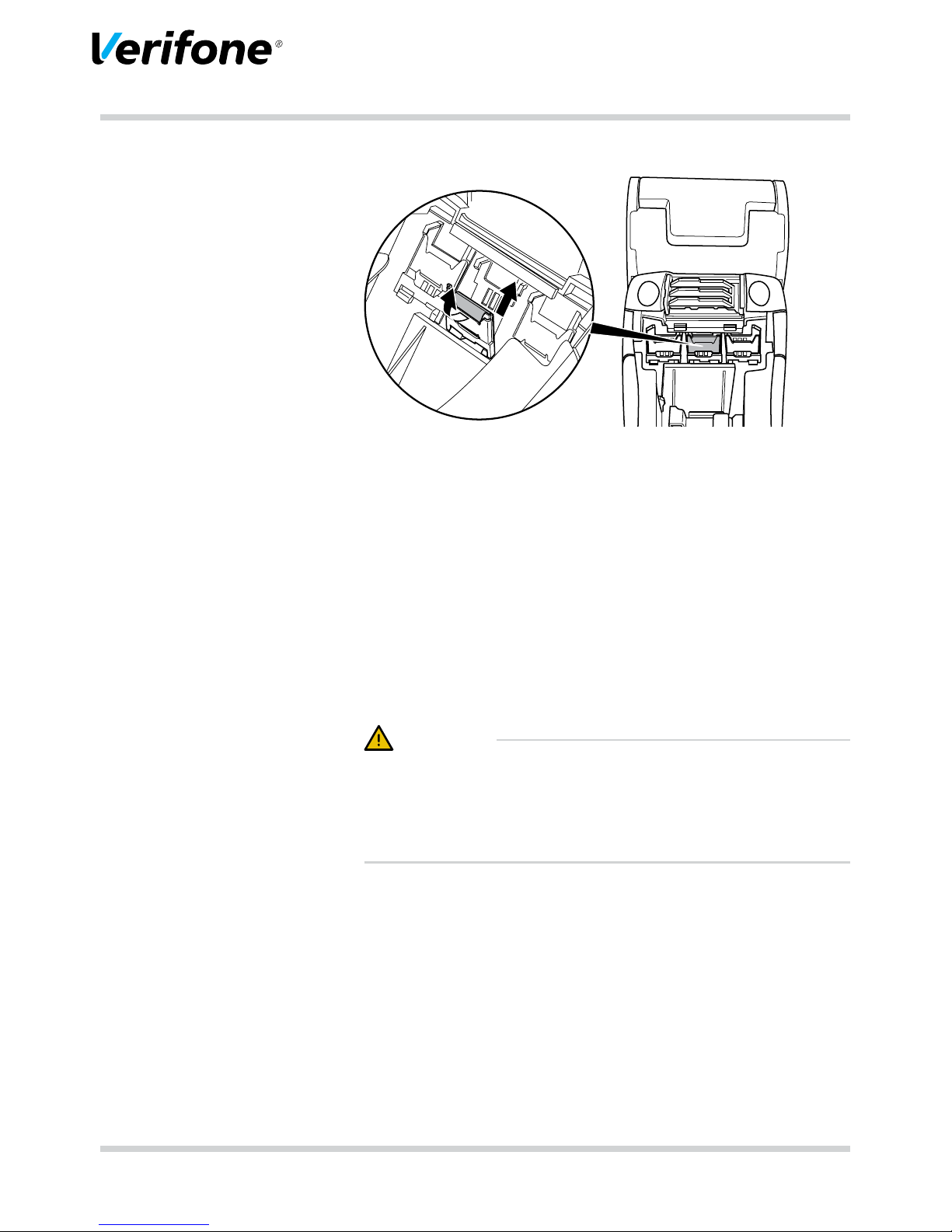
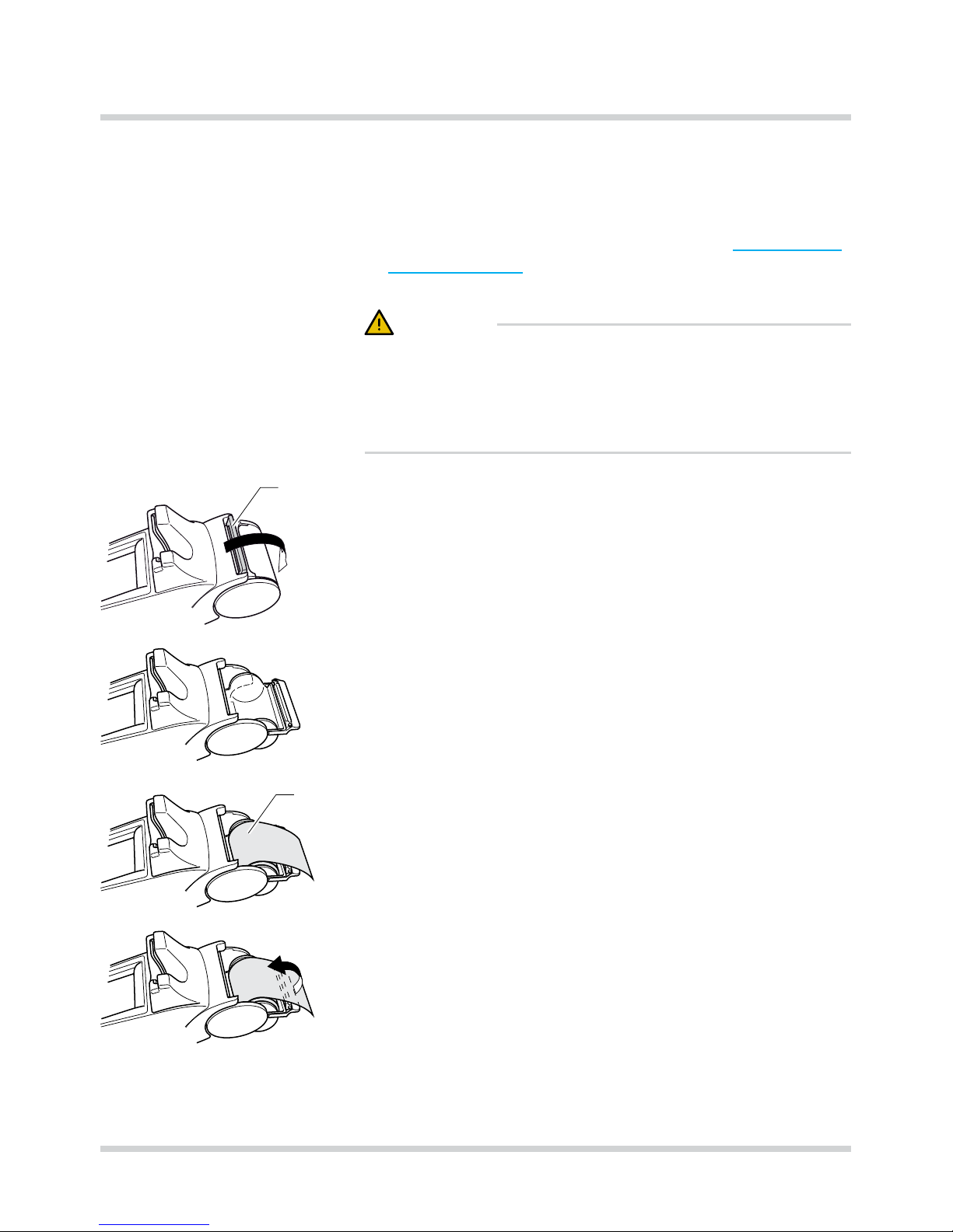
5.3 Inserting the paper roll
i
Only use paper rolls which correspond to
manufacturer’s specication (see chapter 10 Technical
eata on page 51).
CAUTION
Danger of injury due to open paper cutting edge.
► Change the paper rolls carefully.
► Avoid touching the paper cutting edge.
1
► Release the cover (1) of the paper container simultane-
ously from the right and left locking mechanism.
► Turn down the cover completely.
► Fold back the paper container fully to the rear.
2
► Place the paper roll (2) into the paper container so that
the start of the paper protrudes a few centimetres.
► Close the paper container.
The cover of the paper container must engage audibly.
i
The printer only works correctly when the paper
container is closed.
Page 41

Installation Instructions H5000 41
Taking the device into operation
6 Taking the device into operation
Before you can conduct any transactions with the device,
you need to take the device into operation.
Prerequisites for taking the
device into operation
The prerequisites for the taking into operation are:
• The telephone cable (ISND or analogue telephone) /
network cable (LAN) is plugged in.
• A valid Terminal ID is available.
i
You can get the Terminal ID (TID) from your service
provider. The Terminal ID (TID) is an 8-digit number.
Start taking-into-operation
procedure
► Connect the mains lead with the socket.
i
As soon as the device is supplied with power for the rst
time, the taking-into-operation procedure will start.
Select language ► Select the language.
Enter password ► Enter the merchant password.
i
The basic setting of the password is 000000.
► Conrm the entry.
Enter Terminal ID ► Enter the Terminal ID (TID).
► Conrm the entry.
► Enter the Terminal ID again (TID).
► Conrm the entry.
Select RDT module
► Select RDT module.
i
The further procedure of the taking-into-operation is
dependent on the RDT module (LAN / ISDN / Modem):
– LAN module, see chapter 6.3.1 Setting up the LAN
connection on page 42
– ISDN module, see chapter 6.3.2 Setting up ISDN /
Modem connection on page 44
– Modem, see chapter 6.3.2 Setting up ISDN / Modem
connection on page 44
Page 42

42 Installation Instructions H5000
Taking the device into operation
6.3.1 Setting up the LAN connection
After selecting the RDT module LAN the device establishes
the LAN connection itself.
i
Only when an automatic setting up is not possible with
the parameters pre-set in the device, you need to
undertake the following settings:
► Select the corresponding setting:
– Yes: there is a DHCP server in your network which
assigns an IP address to the device (continue with
“assign IP address via DHCP server”).
– No: the IP address is entered manually (continue with
“enter IP address manually”).
Assign IP address via DHCP
server
The IP settings are determined automatically.
Further parameters pre-set by your service provider are
enquired.
► Conrm the pre-set parameters.
The device carries out the taking-into-operation
automatically.
Enter IP address manually
i
One or two-digit values must be entered with leading
zeros.
► Enter the following parameters one after the other:
– IP address of terminal
– Subnet mask of the terminal
– IP address of gateway of terminal
– IP address of DNS of terminal
i
Please contact your network administrator if you have
questions about the parameters to be entered.
► Conrm each entry.
Further parameters pre-set by your service provider are
queried.
► Conrm the pre-set parameters.
Page 43

Installation Instructions H5000 43
Taking the device into operation
Concluding the
taking-into-operation
Further taking-into-operation is carried out automatically. It
takes some time.
The taking-into-operation record is printed. The basic
display for payment transactions is displayed.
After a successful taking-into-operation, the device is
ready for operation.
i
Depending on the conguration of the device, the
display can look differently.
If the taking-into-operation was unsuccessful, “Only menu
is possible” is displayed.
i
For further information see chapter 6.3.3 Taking into-
operation not successful on page 46.
Page 44

44 Installation Instructions H5000
Taking the device into operation
6.3.2 Setting up ISDN / Modem connection
Determine external line
automatically
► Select the corresponding setting:
– Yes: the parameters for the external line are set inde-
pendently.
– No: follow the further points.
Enter external line code
i
A setting is not required in the case of a direct
telephone exchange line.
In the case of telephone PABX systems you must get
the exchange/ lines through a character which is dialled
before the number. Usually this is the “0” as external
line code. In addition, it may be necessary to set waiting
times with the character “-“.
► Select the corresponding setting:
– Yes: External line code required (telephone PABX
system)
– No: External line code not required (direct telephone
exchange line)
With selection Yes: The external line code is set automatically to “0-”. You can also change the external line codes.
► Delete the automatically set external line codes.
► Enter the external line code.
► Conrm the entry.
The entry of digits, letters or special characters required
for the external line is described in chapter 4.5 Enter digits,
text and special characters on page 30.
Page 45

Installation Instructions H5000 45
Taking the device into operation
Concluding the
taking-into-operation
Further taking-into-operation is fully automatic. It takes
some time.
The taking-into-operation record is printed.
The basic display for payment transactions is displayed.
After a successful taking-into-operation the device is ready
for operation.
i
Depending on the conguration of the device, the display can vary in appearance.
If the taking-into-operation was unsuccessful, “Only menu
is possible” is displayed.
i
For further information see chapter 6.3.3 Taking into-
operation not successful on page 46.
Page 46

46 Installation Instructions H5000
Taking the device into operation
6.3.3 Taking into-operation not successful
If the taking-into-operation was unsuccessful, “Only menu
is possible” is displayed.
Possible error causes for an unsuccessful taking-intooperation can be, e.g.:
• Incorrect terminal ID entered
• Incorrect pre-settings
• Incorrect setting for the external line
Re-Start taking-intooperation procedure
► Separate the device from the power supply.
► Reconnect the mains lead with the socket.
The taking-into-operation procedure starts again.
For further information see chapter 6 Taking the device into
operation on page 41.
Troubleshooting If the taking-into-operation was unsuccessful, you can
rectify possible errors as follows:
► Select the function Main menu.
► Check the settings you have performed (see Operating
Instructions, chapter “Setting RDT settings”).
► Rectify possible errors.
► Carry out an extended diagnosis (see chapter 7.1 Ex-
tended diagnosis on page 47).
i
Take note of what is shown on the display and check
the taking-into-operation record. These may possibly
give an indication of the error cause.
i
In case you cannot take the device into operation,
please contact the hotline of your service provider.
Page 47

Installation Instructions H5000 47
Diagnosis
7 Diagnosis
Main menu
Reconciliation
Diagnosis
Administration
...
During the diagnosis, the data on the device are compared
with the data on the network operator computer.
7.1 Extended diagnosis
Main menu
...
Diagnosis
Extended diagnosis
Normal diagnosis
...
► Select the function Extended diagnosis.
Limits, date, time etc. are requested from the service provider and transferred to the device.
i
Pay attention to further error comments on the display
and on printouts. Rectify possible errors and conduct
another Extended diagnosis.
Page 48

48 Installation Instructions H5000
Cleaning and maintenance
8 Cleaning and maintenance
i
Do not use scouring agents or plastic dissolving
cleaners (alcohol, thinners or acetone) for cleaning.
i
You can also clean the keyboard and display with
disinfecting tissues.
8.1.1 Cleaning the display
► Select the function Information.
► Select the function Clean Display.
The device enters the cleaning mode. The display is
locked for operation by nger.
► Leave cleaning mode: Follow the instructions on the
display.
8.1.2 Cleaning the housing
CAUTION
Danger to life through electric shock!
Damage of the device through penetrating water!
► Switch the device off.
► Pull the mains plug out of the socket.
► Never wet clean the device.
► Ensure that liquid cannot penetrate inside the device.
► Clean the device surface with a dry cloth.
► In the case of heavy contamination: Use a moist cloth
which you have dipped in water with a mild detergent
and wrung out well.
Page 49

Installation Instructions H5000 49
Security seal
9 Security seal
The device is tted with a security seal. When removing
this, the seal is damaged irreversibly.
If the seal is damaged, the device may have been opened.
► Check whether the device has a seal which corres-
ponds to the adjacent gure.
The seal serial number is represented as 2D barcode (1)
and in plain text (2).
In plain text, the seal serial number consists of the letter V
followed by 8 digits.
The lock symbol (3) is coloured with security colour shifting
ink. It appears either green or pink, depending on the
viewing angle.
► Check whether the seal is intact.
i
You can identify manipulation easiest at the point where
housing components meet under the seal.
Page 50

50 Installation Instructions H5000
Security seal
Intact seal:
• The seal does not show any mechanical damages, e.g.
cuts or cracks.
• The seal foil shows a uniform grey colour tone.
• The lock symbol appears either uniform green or pink,
depending on the viewing angle.
Damaged seal:
• The seal is damaged e.g. through cuts or cracks.
• Instead of a uniform colour tone the seal shows
honeycombed pale spots.
► When the seal is damaged: Contact your service pro-
vider or your hotline immediately.
► Note the serial number of the seal.
This way you can determine at a later point of time when
the seal on your device was changed.
► Check the seal regularly.
Page 51

Installation Instructions H5000 51
Technical eata
10 Technical eata
10.1 H5000
H5000 with printer H5000 without printer
Dimensions (L x W x H) 280 mm x 90 mm x 125 mm 225 mm x 90 mm x 125 mm
Weight 665 g 516 g
Power supply Table power pack (Manufacturer Channel Well Tech. Co.
Ltd.),
100 V to 240 V / 50 Hz to 60 Hz,
9.3 VDC/4A
Memory 256 MB Flash
256 MB SDRAM
1 MB SRAM
Processor 32-bit ARM 11 / 400 MHz
Printer Thermal printer, up to 22
lines per second
–
Graphic Display 3.5 inch, touch sensitive colour touch display
Keyboard 15 keys, EBS standard, back-lit, additional softkeys
(programmable function keys) via touch sensitive colour
touch display.
Card reader Contactless card reader
Hybrid reader for chip and magnetic strip cards
Illuminated card slot
3 plug-in slots (SAM)
Micro-SD card slot
Interfaces Power supply: 9.3 VDC +/- 10 % / 4 A
Serial: 2 times RS-232 (1-times current applied)
USB Host / USB OTG
Bluetooth Class 2 (10 m) (optional)
WiFi 802.11 b/g/n (optional
Integratable DFU-Modules Ethernet
ISDN/Modem Combi.modem
GPRS (optional)
Operating temperature 0 °C to +45 °C
Rel. humidity 15 % to 85 %, not condensing
Storage temperature -20 °C bis +70 °C
Rel. humidity 15 % to 85 %, not condensing
Page 52

10.2 Replacement paper roll (thermal paper)
Width 58 mm +0 / −1,0 mm
Roll diameter Max. 60 mm
Paper thickness 65 µm +5 / −5 µm
Paper colour White
Development colour Black
Thermal sensitivity Standard
Page 53

Page 54

Verifone GmbH
Konrad-Zuse-Str. 19-21
36251 Bad Hersfeld
Germany
www.verifone.com
info-germany@verifone.com
WEEE-Reg.-Nr. DE 58713050
H5000
Installation Instructions DOC450-005-EN-A Rev. A00
© 2016 Verifone GmbH
 Loading...