

Page 1

Forecourt Controller
Forecourt Controller Interface
Interface
Installation Guide
Date: August 11, 2016
Page 2

Page 3

Forecourt Controller Interface Installation Guide
August 11, 2016
Verifone
88 West Plumeria Drive
San Jose, CA
Telephone: 408-232-7800
http://www.verifone.com
Printed in the United States of America.
© 2016 Verifone, Inc. All rights reserved.
No part of this publication covered by the copyrights hereon may be reproduced or copied in
any form or by any means - graphic, electronic, or mechanical, including photocopying, taping,
or information storage and retrieval systems - without written permission of the publisher.
The content of this document is subject to change without notice. The information contained
herein does not represent a commitment on the part of Verifone. All features and
specifications are subject to change without notice.
Verifone, Ruby SuperSystem, and Secure PumpPAY are registered trademarks of Verifone, Inc.
Ruby Card, iOrder, and Commander Site Controller are trademarks of Verifone. All other brand
names and trademarks mentioned in this document are the properties of their respective
holders.
®
, Inc.
95134
Page 4

Forecourt Controller Interface Installation Guide
Revision History
Date Description
June 25, 2012
November 2, 2012
May 1, 2014
June 19, 2014
September 19, 2014
March 25, 2015
August 11, 2016
Initial documentation release.
Added Warning below. Also, added new part numbers
for the FCI kit and manual.
Added references to Commander Site Controller and
current loop board changes.
Added Tokheim and Bennett
Added information regarding Tokheim and Bennett
RS485 board connections and added Current Loop
Jumper Settings.
Added SFC section.
Updated the Determing a Location section, Tokheim
TED, added a Megger Test note to the Connecting the
Dispenser Control Cables section, and added Product
Warranty information to the Introduction.
Page 5

WARNING!
1. This equipment is not intended to be repaired by the user. All
repairs must be performed by an Authorized Service Technician or
a Verifone VASC.
2. The AC Outlet must be within six feet of the Forecourt Controller
Interface unit.
3. The power supply cord must not be attached to the building
surface nor through wall, ceilings, floors, or similar openings in
the building structure.
4. Installation measures must be taken to prevent physical damage
to the power supply cord, including proper routing of the power
supply cord.
5. When replacing the cover on the Forecourt Controller Interface,
tighten the thumbscrews securely with a screwdriver.
Page 6

Page 7

Forecourt Controller Interface Installation Guide i
Contents
1. Introduction. . . . . . . . . . . . . . . . . . . . . . . . . . 1
Product Warranty. . . . . . . . . . . . . . . . . . . . . . . . . . . . . . . 1
Description . . . . . . . . . . . . . . . . . . . . . . . . . . . . . . . . . . . . . 1
Before You Install . . . . . . . . . . . . . . . . . . . . . . . . . . . . . . . . . 2
Unpacking. . . . . . . . . . . . . . . . . . . . . . . . . . . . . . . . . . . . 2
Contents. . . . . . . . . . . . . . . . . . . . . . . . . . . . . . . . . . . . . 2
General Requirements . . . . . . . . . . . . . . . . . . . . . . . . . . . . . . 3
Safety Instructions . . . . . . . . . . . . . . . . . . . . . . . . . . . . . . . . 4
2. Installing the Forecourt Controller Interface Box 7
Determining a Location . . . . . . . . . . . . . . . . . . . . . . . . . . . . . 7
Existing Equipment . . . . . . . . . . . . . . . . . . . . . . . . . . . . . . . . 8
Sites required to use the Smart Fuel Controller (SFC) . . . . . . . 8
Gilbarco Sites . . . . . . . . . . . . . . . . . . . . . . . . . . . . . . . . . 8
Wayne Sites . . . . . . . . . . . . . . . . . . . . . . . . . . . . . . . . . . 9
Tokheim Sites . . . . . . . . . . . . . . . . . . . . . . . . . . . . 11
Bennett Sites . . . . . . . . . . . . . . . . . . . . . . . . . . . . . 12
Preparing to Install . . . . . . . . . . . . . . . . . . . . . . . . . . . . . . . 13
Installing the Forecourt Controller Interface Box. . . . . . . . . . . . 14
Installing the Boards . . . . . . . . . . . . . . . . . . . . . . . . . . . . 14
Mounting the Unit . . . . . . . . . . . . . . . . . . . . . . . . . . . . . 20
Connecting the Dispenser Control Cables. . . . . . . . . . . . . . . . . 22
Connecting to Current Loop Boards . . . . . . . . . . . . . . . . . . 23
Connecting to RS485 Boards . . . . . . . . . . . . . . . . . . . . . . . 26
Connecting to a Tokheim TED . . . . . . . . . . . . . . . . . . . . . . . . 29
Completing the Installation. . . . . . . . . . . . . . . . . . . . . . . . . . 30
August 11, 2016
Page 8

ii Forecourt Controller Interface Installation Guide
August 11, 2016
Page 9

1 INTRODUCTION
Forecourt Controller Interface Box
This guide provides instructions for installing the Verifone® Forecourt Controller
Interface (FCI) Box.
Product Warranty
For Product warranty information, go to
http://global.verifone.com/company/terms-and-conditions/
Description
The Forecourt Controller Interface allows fuel and DCR communications
between the dispensers and the Commander Site Controller.
Note: The Forecourt Controller Interface is not used for fuel communication
for Tokheim, Bennett, and sites required to use the Smart Fuel
Controller (SFC).
.
August 11, 2016
Page 10

2 Forecourt Controller Interface Installation Guide
The FCI box can hold up to four current loop or RS485 boards (or a combination
of both). Each board can support up to 16 fueling positions. The FCI box comes
with one current loop board installed. Additional boards must be ordered
separately.
• Current Loop Board (Kit # 29721-01) — Supports both current loop and
RS232 communications.
• RS485 Board (Kit # 29376-01) — Supports RS485 communications and must
be used for Dresser Wayne CAT/Ovation, Tokheim DPT, Bennett Secure
Payment Module (SPM), and Verifone Secure PumpPAY installations.
Before You Install
This section describes the components supplied with the Forecourt Controller
Interface box.
Unpacking
Carefully inspect the shipping carton and its contents for any damage that might
have occurred during shipment. If anything appears damaged, immediately file
a claim with the shipping company or carrier and notify your Verifone
representative.
Never use damaged equipment. A shock or fire hazard may exist if equipment is
energized in a damaged condition.
Contents
Remove the components from the packaging and place them on a table or
counter top. Make certain you have all the parts listed in Table 1 before you
begin. Contact the Verifone Technical Support Center if you are missing
anything.
Note: Keep the shipping carton and any packing material in case it is necessary
to move components from one location to another or to return the
equipment for service.
Note: One FCI box supports up to 32 fueling positions.
August 11, 2016
Page 11

Forecourt Controller Interface Installation Guide 3
Table 1: Forecourt Controller Interface Box (P/N M149-901-01-R)
Quantity Item Verifone Part Number
(1) unit Forecourt Controller Interface
Box
Includes:
- Locking ribbon cables (4)
- AC Power Cable
- Current Loop Board
(1) per unit Forecourt Controller Interface
Installation Guide
Table 2: Materials Provided by Installer
Quantity Item
Various lengths 18 AWG plenum rated twisted-pair cable (for example,
Belden P/N 88760). Lengths depend on configuration.
(20) per unit Wire nuts for splicing 18 AWG wires
(3) per unit 1-inch metallic conduit fittings
M149-901-01-R
DOC149-901-01-R,
Revision C00
(1) per unit 1/2-inch Romex cable clamp
(4) per unit #8, 1-1/2 inch wood screws
(4) per unit 1/8 inch toggle bolts. 3 inches long
General Requirements
August 11, 2016
Before you start, read the following important information:
1. Changes or modifications not expressly approved by Verifone, Inc., could
void the user’s authority to operate this equipment.
2. This equipment is not intended to be repaired by the user. All repairs
must be performed by an Authorized Service Technician or a Verifone
VASC .
3. All installations must comply with the requirements of the National
Electrical Code (NFPA 70), the Code for Fuel Dispensing Facilities and
Repair Garages (NFPA 30 and 30A), OSHA regulations, including Standard
29 CFR 1910.147, and all other applicable national and local codes.
Page 12

4 Forecourt Controller Interface Installation Guide
4. The circuit providing power to the Forecourt Controller Interface unit
must not power other devices. The AC outlet must be within six feet of
the Forecourt Controller Interface unit. Do not use extension cords.
5. The power supply cord must not be attached to the building surface nor
through walls, ceilings, floors, or similar openings in the building
structure.
6. Installation measures must be taken to prevent physical damage to the
power supply cord, including proper routing of the power supply cord.
7. Do not connect the Forecourt Controller Interface unit to the AC power
until the installation is complete.
8. Always wear an electrostatic wrist strap. Working on console electronics
without connecting to a ground or discharging static can damage
electronic parts.
9. When replacing the cover on the Forecourt Controller Interface
enclosure, tighten the screws securely with a Phillips screwdriver.
Safety Instructions
For safe disassembly and installation of this equipment, read and understand all
safety notices.
WARNING: You must be a Verifone Authorized Service Contractor
DANGER means: If you do not follow the instructions, severe injury or
WARNING means: If you do not follow the instructions, severe injury or
CAUTION means: If you do not follow the instructions, damage to the
CAUTION: High voltage. To be serviced by authorized service
(VASC) with training in the installation, service, or
maintenance of this equipment before working on it.
death will occur.
death can occur.
equipment can occur.
personnel only.
CAUTION: There is a risk of explosion if the battery is replaced by
an incorrect type. Dispose of used batteries according to
the instructions.
August 11, 2016
Page 13

Forecourt Controller Interface Installation Guide 5
DANGER: Disconnect all power to this equipment during
installation, service, or maintenace. Tag breakers to
prevent others from reconnecting power.
DANGER: This equipment is to be installed in an indoor location
only. Do not install this equipment in a hazardous
location.
WARNING: Make sure this equipment is correctly grounded. Failure
to do so can cause injury or damage to the equipment.
August 11, 2016
Page 14

6 Forecourt Controller Interface Installation Guide
August 11, 2016
Page 15

2 INSTALLING THE FORECOURT
C
ONTROLLER INTERFACE BOX
This chapter provides instructions for installing the Forecourt Controller
Interface (FCI) box.
You can install the FCI box with
• Up to four current loop boards
• Up to four RS485 boards
• Any combination of current loop boards and RS485 boards (up to four
boards)
Warning:Before you begin to install the Forecourt Controller Interface box,
be sure all power to the existing distribution box and PAM or
Electronics Cabinet is disconnected at the main panel. Multiple
disconnects may be required to de-energize these devices. (Refer to
the General Requirements section in Chapter 1.)
Determining a Location
August 11, 2016
The Forecourt Controller Interface box must be mounted in an indoor location.
Locate the box at least 18 inches above the floor in an area where liquids will
not be spilled onto it.
Note: The Forecourt Controller Interface box is to be mounted in an indoor
location only. The box is not to be used in a hazardous location. Do not
mount the Forecourt Controller Interface in a fuel dispenser.
Avoid the following locations:
• DO NOT install less than six inches near or inside electrical panels
• DO NOT install less than six inches near submersible pump controllers or
along side wiring to these devices
• DO NOT install less than six inches near submersible pump relays
Page 16
8 Forecourt Controller Interface Installation Guide
Distribution Box
Dispenser Communications Cables
Existing Equipment
Note: Dispose of all removed components in an appropriate manner as
approved by the site owner.
Sites required to use the Smart Fuel Controller (SFC)
Note: The Commander Site Controller application must be at base 32 or higher
OR supports POP Discounts and loyalty using the Smart Fuel Controller.
If the site is required to use the Smart Fuel Controller for fuel, then the Current
Loop boards are not needed in the FCI box. The FCI box and RS-485 boards are
still needed for the DCRs. A RS-232 cable is required from the Commander Site
Controller to the SFC box. See the Smart Fuel Controller Installation Guide on
the Verifone Premier Portal at Petro Downloads > Verifone Fuel Controllers >
Smart Fuel Controller for more information.
Gilbarco Sites
If there is an existing distribution box at the site, disconnect the cables from the
box and remove it. It is not used with the Forecourt Controller Interface. The
Forecourt Controller Interface box can be mounted in the same location.
The dispenser control cables will be reconnected to the Forecourt Controller
Interface.
Also, disconnect and remove the PAM. It is not used with the FCI box.
August 11, 2016
Page 17

Forecourt Controller Interface Installation Guide 9
PAM
Dispenser Control Cables
Cables to Electronics
Cabinet
Outside of Distribution Box
Wayne Sites
If there is a Wayne distribution box, disconnect all the dispenser control cables.
The terminals on the distribution box are marked (
+) wires. The dispenser control cables will be reconnected to the FCI. Also,
(
disconnect the cables that go to the Electronics Cabinet.
+) and (–); mark the positive
Remove the distribution box. It is not used with the FCI. The FCI box can be
mounted in the same location.
Remove the Electronics Cabinet and all the cables connected to it. It is not
reused.
August 11, 2016
Page 18

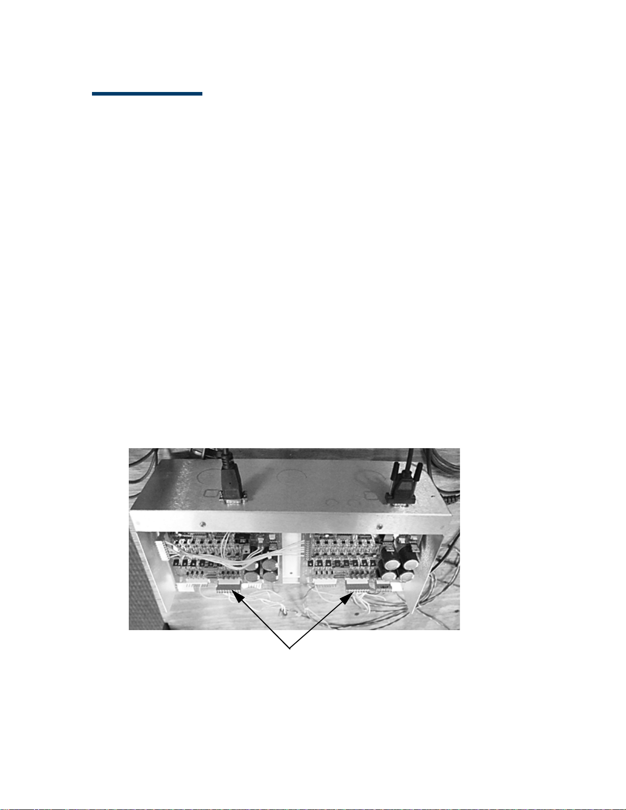
10 Forecourt Controller Interface Installation Guide
Wayne Electronics Cabinet
August 11, 2016
Page 19

Forecourt Controller Interface Installation Guide 11
Tokheim DHC/VXDHC
To k he i m S i t e s
The FCI Box does not control Tokheim fuel communications. Tokheim sites
require a VXDHC or DHC box. Use a RS-232 cable (P/N 13836-XX) and red null
modem connector (P/N 13581-01) to connect the Commander Site Controller to
the VXDHC or DHC.
Note: If the Verifone Site Controller is being replaced rather than a new
installation, use the existing VXDHC/DHC box, cable and connector as
described above.
August 11, 2016
Page 20

12 Forecourt Controller Interface Installation Guide
Bennett 515 Box
Bennett Sites
The FCI Box does not control Bennett fuel communications. Bennett sites
require a 515 Box. Use a RS-232 cable (P/N 13836-XX) and black straight through
connector (P/N 13641-01) to connect the Commander Site Controller to the 515
Box.
Note: If the Verifone Site Controller is being replaced rather than a new
installation, use the existing 515 box, cable and connector as described
above.
August 11, 2016
Page 21

Forecourt Controller Interface Installation Guide 13
Thumbscrews (2)
Preparing to Install
Before you begin the installation, loosen the two thumbscrews that attach the
cover of the FCI enclosure. Push the cover forward 1/2- inch and lift.
August 11, 2016
Page 22

14 Forecourt Controller Interface Installation Guide
Ribbon Cable
Connector
Power
Connector
Loop Cable Connectors
Installing the Forecourt Controller Interface Box
This section describes how to install the distribution boards and mount the FCI
box on the wall.
Installing the Boards
Note: The Forecourt Controller Interface box come with one current loop
board installed. Additional boards must be ordered separately.
Installing the Current Loop Boards
The current loop boards (Kit # 29721-01) support both current loop and RS232
communications. (For RS485 communications, go to the section Installing the
RS485 Boards.)
To install the current loop boards:
1. Locate the current loop board (P/N 29521-01-R) provided with the
Current Loop Board kit.
August 11, 2016
Page 23

Forecourt Controller Interface Installation Guide 15
Mounting Post Locations
1
2
3
4
2. Locate the mounting posts on the FCI box.
August 11, 2016
Page 24

16 Forecourt Controller Interface Installation Guide
Screw Locations (4)
COM Ports
3. Position the first current loop board over the mounting posts in
location 1 above, and secure the board to the posts using the four screws
(P/N SCR-0001) provided with the Current Loop Board kit.
August 11, 2016
Page 25

Forecourt Controller Interface Installation Guide 17
Connector Blocks (8)
Ribbon Cable
Connector
Power
Connector
4. Repeat these steps to install additional boards, installing the boards in
locations 2, 3, and 4 as shown in the picture in step 2 above.
Jumper Settings for Current Loop Boards
Verify that the jumper settings below are correctly set for Commander.
– JP9—CL current selector: 20mA, 30mA, or 45mA (default)
– JP10—Select Communication mode: 1-2=Current Loop (CL),
2-3=RS232(default)
– JP11—A test point ground that should remain empty
(no jumper)
– JP13—Select Master/Client board: 1-2=Master, 2-3=Client
Installing the RS485 Boards
The RS485 Board 8-Channel Interface Kit (Kit # 29376-01) supports RS485
communications and must be used for Dresser Wayne CAT/Ovation, Tokheim
DPT, Bennett Secure Payment Module (SPM), and Verifone Secure PumpPAY
installations.
To install the RS485 boards:
1. Locate the RS485 board (P/N 18806-01-R) provided with the RS485 kit.
August 11, 2016
Page 26

18 Forecourt Controller Interface Installation Guide
Mounting Post Locations
1
2
3
4
2. Locate the mounting posts on the FCI box.
August 11, 2016
Page 27

Forecourt Controller Interface Installation Guide 19
Screw Locations (4)
COM Ports
3. Locate the four screws (P/N SCR-0001) provided with the RS485 Board
kit.
4. Position the RS485 board over the mounting posts in location 1 above.
Secure the board to the posts using the four screws.
August 11, 2016
5. Repeat these steps to install additional boards, installing the boards in
locations 2, 3, and 4 as shown in the picture in step 2 above.
Jumper Settings for RS485 Boards
– JP3—Connects signal ground (GND) to chassis ground (default is
connected)
Note: The jumper settings should not be changed.
Page 28

20 Forecourt Controller Interface Installation Guide
Knockout Locations
Mounting the Unit
Before you mount the unit, remove one or more of the 1-inch knockouts into
which to install 1-inch conduit fittings for routing the dispenser control wires.
The number of knockouts to be removed will depend on how many dispenser
control wires there are. It will be easier to do this now than after the units are
mounted.
Install 1-inch metallic conduit fittings into the knockout holes where the
dispenser control wires will enter the enclosure. More than one fitting may be
needed, depending on the number of dispenser control wires.
Mount the FCI unit in the orientation shown in to the following illustration. This
provides convenient access to the dispenser control cables, which, at most
sites, come up through a conduit in the floor.
August 11, 2016
Page 29
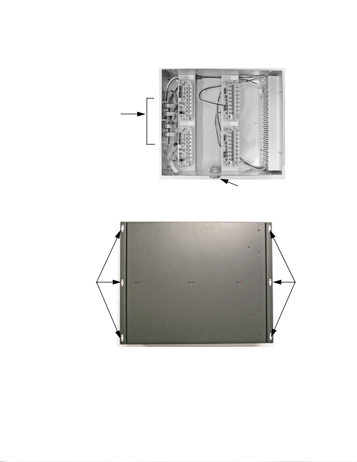
Forecourt Controller Interface Installation Guide 21
COM
Ports
Forecourt Controller Interface Box
Conduit Fitting
Screw
Holes
Screw
Holes
Rear View
Mount the FCI box securely to the wall with toggle bolts through the pre-drilled
tabs.
August 11, 2016
To mount the FCI Box:
1. Using the box as a template, mark the hole placement for the four toggle
bolts on the desired wall location where the distribution boards can be
easily connected to the existing dispenser control cables.
Page 30

22 Forecourt Controller Interface Installation Guide
Dispenser Control
Cable
2. For mounting into drywall, use four 1/8-inch toggle bolts, 3 inches long.
To install the toggle bolts:
a. Open a hole of the recommended size (usually 3/8 or 1/2 inch) at the
center of the holes marked in step 2.
b. Mount the toggle bolts to the pre-drilled tabs on the unit.
c. Push the toggle bolts through the wall hole and tighten securely.
Connecting the Dispenser Control Cables
Note: Before connecting the dispenser control cables to the FCI box, the
Megger Test must be used. The Megger Test checks the quality of the
cable insulation. The dispenser control cables routed from the dispenser
to the FCI box must not be less than six inches to the proximity of power
or other data cables.
Dispensers are connected to the FCI using the existing dispenser control cables
previously connected to the distribution box.
1. Locate the dispenser control cables previously removed from the
distribution box.
2. Do one of the following:
– For Gilbarco dispensers, remove the wire nuts that connect the
dispenser control wires to the existing distribution box connectors.
Set aside the wire nuts for reuse.
– For Wayne dispensers, strip 1/2-inch of insulation from each wire on
the dispenser control cable twisted pair, if not already stripped.
August 11, 2016
Page 31

Forecourt Controller Interface Installation Guide 23
Conduit
Fitting
Dispenser Control
Wires
Positive (+) Wire
Protective
Tips
3. Route the dispenser control wires through the conduit fittings installed
earlier.
Connecting to Current Loop Boards
1. Locate the loop cables provided with the Current Loop Board kit. Eight
loop cables can be connected to each distribution board. Connecting all
cables will result in connections for 8 dispensers. These cables will be
spliced to the dispenser control cables.
2. Remove the black protective tips and strip I/2-inch from each wire and
twist the ends. Leave the protective tips on wires that will not be spliced
to dispenser control cables.
August 11, 2016
Page 32

24 Forecourt Controller Interface Installation Guide
Twisted
Loop
Cables
Pair
Loop Cables
Connected to
Board
3. Using wire nuts, connect one dispenser control wire to each FCI current
loop wire. Connect positive (
distribution board. Note that it might be necessary to reverse some of
the connections after you check the communications from the FCI to the
dispensers.
Note: At sites that have both Gilbarco and Wayne dispensers, both can
be connected to the same FCI unit but the dispenser control
wires must be connected to different distribution boards.
4. Connect all loop cables to the loop cable distribution board.
+) to positive. Repeat for each current loop
August 11, 2016
Page 33

Forecourt Controller Interface Installation Guide 25
Board 1 Board 2 Board 3 Board 4
Power
Cable
Ribbon
Cable
5. Connect the power cable and one of the communications ribbon cables
to the current loop board. Connect the ribbon cables in the order shown.
6. Repeat steps 1 - 5 to connect additional current loop boards.
August 11, 2016
Page 34

26 Forecourt Controller Interface Installation Guide
Single Wire
Chassis Ground
Drain/Ground Wires
Connector Blocks (8)
Connecting to RS485 Boards
Note: At sites with Tokheim and Bennett, all of the drain or ground wires are
tied together to a single wire connected to chassis ground using a wire
nut as shown below.
The RS485 board has eight connector blocks, which can support up to 16 fueling
points with two DCR wires connected to each block, or up to 32 fueling points
with four wires connected to each block.
1. Unplug the required number of connector blocks for the number of
dispenser points.
August 11, 2016
Page 35

Forecourt Controller Interface Installation Guide 27
Connector Block with 2 Wires
Screws
—
+
Connector Block with 4 Wires
Screws
—
+
2. Strip 1/4-inch of insulation from each DCR wire and twist the ends.
Connect the wires to the connector blocks and secure by tightening the
screws on the connector block.
3. Insert the connector blocks back into the RS485 board.
August 11, 2016
Page 36

28 Forecourt Controller Interface Installation Guide
Board 1 Board 2 Board 3 Board 4
Power
Cable
Ribbon
Cable
4. Connect the power cable and one of the ribbon cables to the current
loop board. Connect the ribbon cables in the order shown.
5. Repeat steps 1 - 4 to connect additional RS485 boards.
August 11, 2016
Page 37

Forecourt Controller Interface Installation Guide 29
Connecting to a Tokheim TED
The TED will connect to a single channel of an RS485 board in the FCI. Tokheim
uses three wires for DPT connections (Positive, Negative and Ground). The single
ground wire coming into the FCI from the TED should be grounded to the lower
left mounting screw of the RS485 board.
August 11, 2016
Page 38

30 Forecourt Controller Interface Installation Guide
COM1 COM2 COM3 COM4
AC Power
Connector
Completing the Installation
This section provides instructions for closing up the box, connecting
communications cables between the Forecourt Controller Interface and the
Commander Site Controller, and connecting to the AC power supply.
1. Replace the cover on the enclosure and secure by tightening the two
thumbscrews.
2. Connect the serial cables with RJ45 connectors (provided with the
Commander Site Controller) to the RJ45 ports on the front of the FCI
box.
3. Route the serial cables to the Commander Site Controller and connect
according to the instructions in the Commander Site Controller
documentation.
Caution: When installing the cables, make sure they are protected from
damage or accidental disconnection. Route cables along a wall or
under a counter and secure with cable ties or clips. Do not route
cables near sources of possible interference, such as fluorescent
lights, microwaves, intercoms and so forth.
4. Locate the AC power cord provided with the unit.
5. Locate the AC power connector on the end of the FCI enclosure.
August 11, 2016
Page 39

Forecourt Controller Interface Installation Guide 31
6. Plug the female end of the power cord into the power connector on the
FCI box. Make sure the connector locks securely in place.
7. Plug the other end of the power cord into the dedicated AC outlet.
Caution: The circuit providing power to the FCI unit must not power other
devices. The AC outlet must be within six feet of the FCI unit. Do not
use extension cords.
The power supply cord must not be attached to the building surface
nor through walls, ceilings, floors, or similar openings in the
building structure.
Installation measures must be taken to prevent physical damage to
the power supply cord, including proper routing of the power supply
cord.
8. Restore power to the circuit.
August 11, 2016
 Loading...