

Vericom V-Sense Series, Profile X1 User Manual
V-Sense
TM
Series + Profile X1©
User Guide
The Vericom V-SenseTM series of data acquisition instruments and Profile X1© analysis software is a
combination of sensor instrumentation and analysis software that offers significant flexibility for testing
nearly any moving object or vibration application. If you can find a way to attach the V-Sense POD to the
test object, you can quickly and easily collect the targeted data (for many applications, the heavy-duty
vacuum cup mounting system provided with the package is the perfect option for mounting the sensor
unit). The test files are then analyzed with the Vericom Profile X1 analysis software. Vericom Profile X1
is also very easy to use – yet very sophisticated and powerful. Optionally, you can elect to add up to 12
external analog sensors to the V-Sense POD for collection of a wide variety of data from almost any low
voltage analog sensor (0-5v).
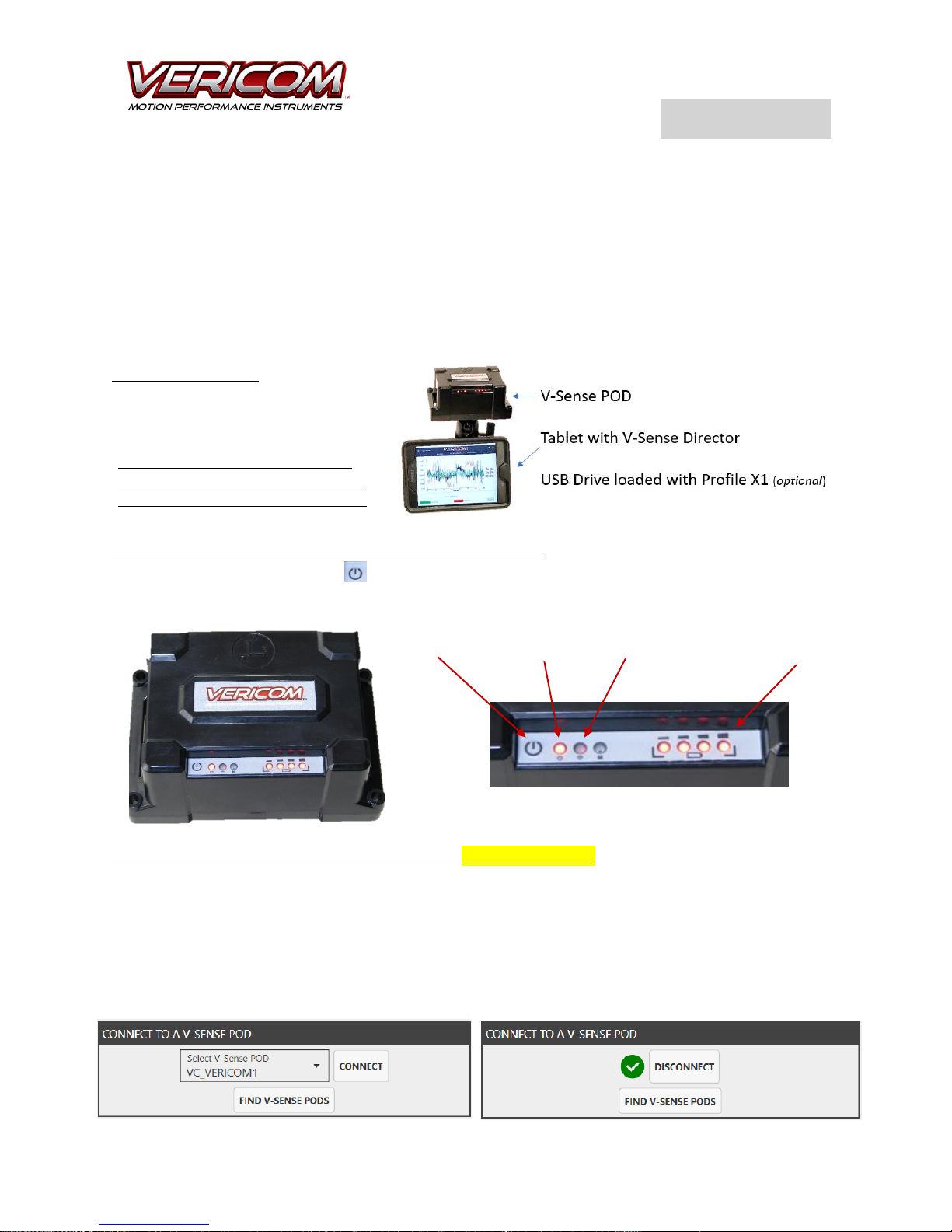
What’s Included:
V-Sense POD LED Panel – Power ON/OFF, Battery, Connected:
Press and hold the power button (hold for ~3 seconds to power on or off). The light on the far left of
the LED panel will illuminate when power is ‘on.’ The 4 LED lights on the right side of the LED panel
indicate the battery level of the V-Sense POD.
Connect a V-Sense POD to the Tablet or PC with wireless Bluetooth: The tablet is preloaded with the
Vericom V-Sense Director application. It is also preconfigured to connect to the V-Sense POD included
within the case. While 1 tablet can be configured to connect to multiple V-Sense PODs, it is recommended
that the tablet and POD that shipped together are repacked in the same case. To connect the tablet/PC
to the V-Sense POD with the Bluetooth, power on the POD and then open the Tools screen on the Vericom
V-Sense Director app (tablet) or Profile X1 (PC). From the drop-down box, select the POD for the
connection. Then click the ‘Connect’ button. Once the POD is connected, the connection box will show a
green check mark and the connect button will become a ‘Disconnect’ button.
• Wall Charger/Power Supply
• 12V DC Charger (Automobile)
• Heavy Duty Vacuum Cup Mount
The V-Sense User Guide is at Vericom
Website, on the USB Drive, or found on
Profile X1 under the Tools menu screen.
Power Button V-Sense is ON V-Sense Connected Light V-Sense POD Battery Level
V-Sense
TM
Series + Profile X1©
User Guide
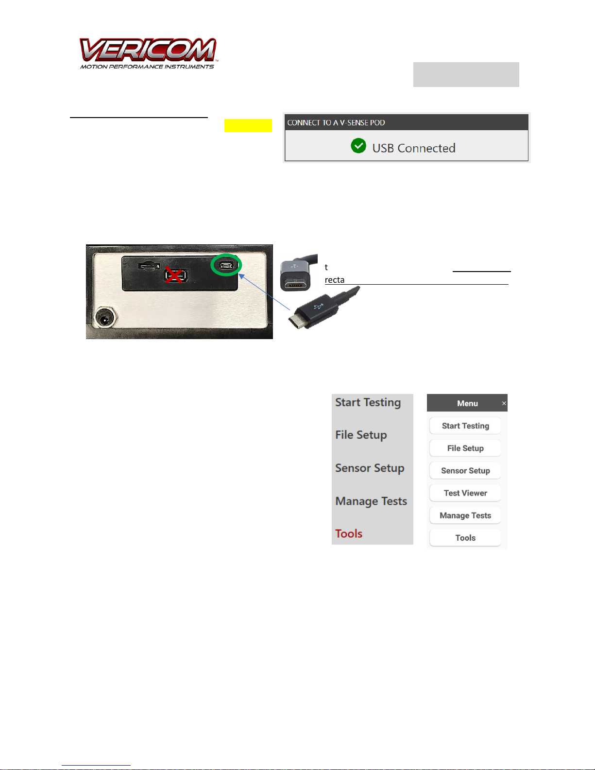
Connect a V-Sense POD to a PC: To connect a
V-Sense POD to a PC with the USB cable,
connect the cable and power the POD. When
the POD is on and connected with the USB
cable, Profile will automatically connect. To
disconnect the POD, simply power off the POD or disconnect the USB cable. Connecting a V-Sense POD
using Bluetooth requires following the same process as described for connecting a POD to the tablet.
Connect the micro-USB end on the USB cable to the POD micro-USB connector. Connect the common
USB end (rectangular shape) to the PC USB port.
The Profile X1© software includes 5 primary screens: Start
Testing, File Setup, Sensor Setup, Manage Tests, and
Tools. The V-Sense Director tablet app incudes 1
additional screen for basic test viewer capability (Test
Viewer).
Profile X1 Screens (PC)
V-Sense Director
(Tablet App)
Connect micro-USB to the V-Sense POD. Then
use the common ‘rectangular port on the PC for
the other end of the USB cable. Do not use the
rectangular USB from the POD to PC or Tablet!
V-Sense
TM
Series + Profile X1©
User Guide
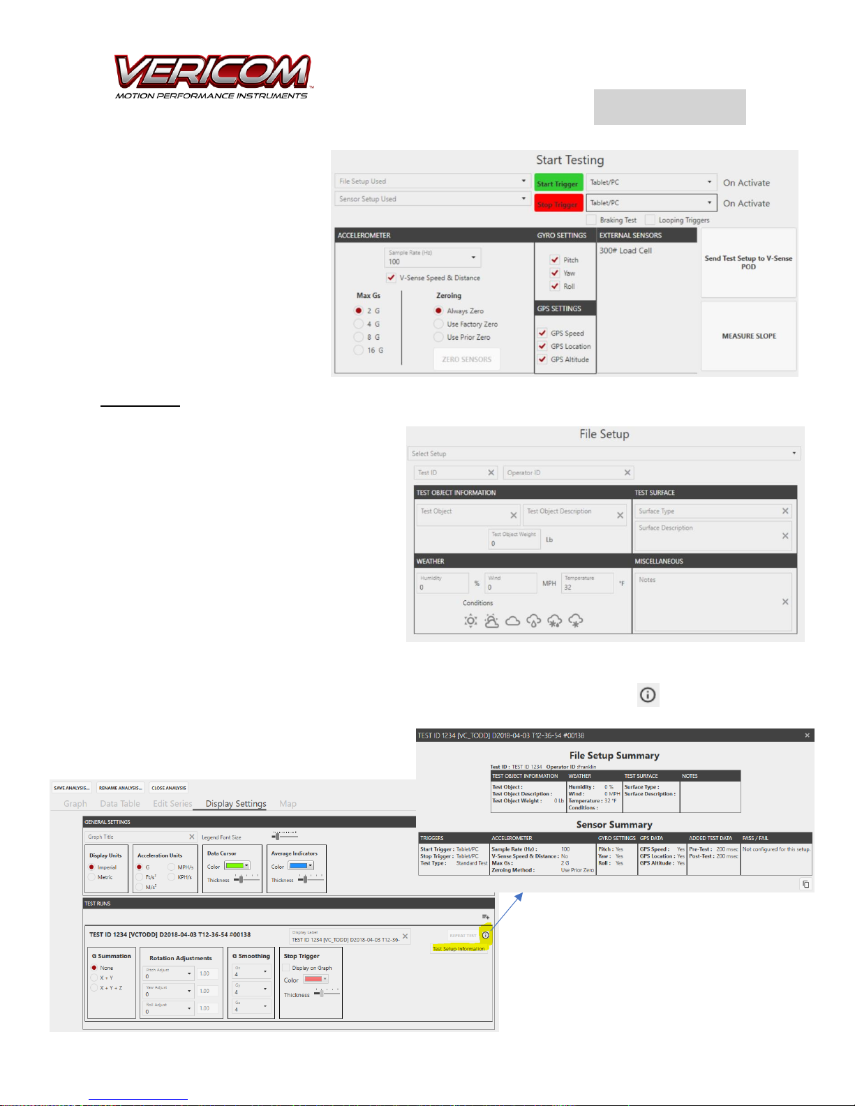
The Start Testing view includes
common Sensor Setup options and
is the screen from where all testing
is initiated. This screen includes
the ‘Send Test Setup’ button –
which is used to send the test
instructions to the V-Sense POD.
Later in this User Guide, you will
find additional details regarding
the Start Testing screen.
File Setup
The File Setup screen for both Profile X1 and
the tablet app (V-Sense Director) provide the
same general functionality. Use the File Setup
screen to add context and information that you
want to attach to the test file. As desired you
can add a Test ID, Operator ID, and additional
description information for a specific test. A
File Setup can be saved with a specific name
and reused as needed. In addition, if a Test ID
is added, that Test ID is included with the test
file name by adding that information to the
beginning of the file name.
The File Setup details can be reviewed from Profile X1. Open a test file, select the Display Settings tab,
click on the ‘information’ icon for the specific test. After clicking on the ‘information’ icon, a pop-up
window will show the File Setup and Sensor Setup information.
V-Sense
TM
Series + Profile X1©
User Guide
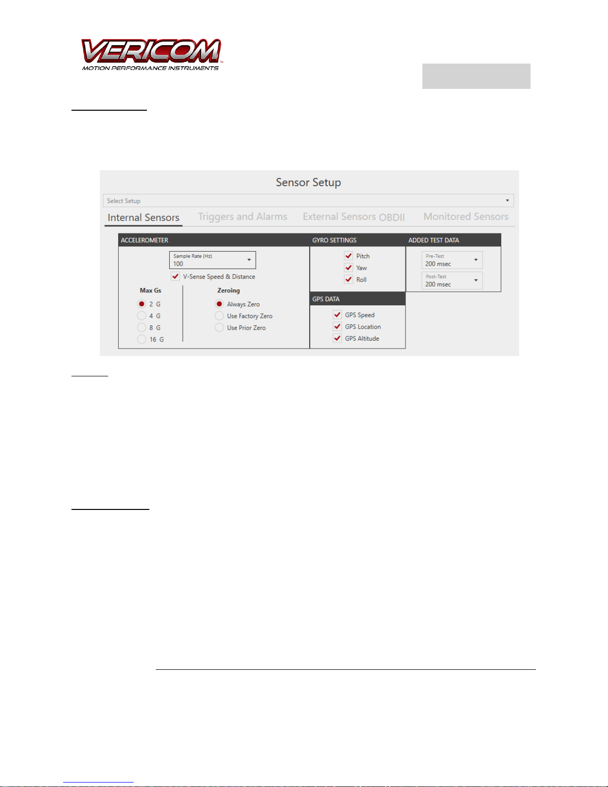
Sensor Setup
The Sensor Setup screen is where you define the sensors that are ‘ON/OFF’ for each specific test. In
addition, this is where the Start/Stop Triggers and Alarms are defined. The Sensor Setup area is also
used to identify the sensor data you want to view on the testing screen while a test is in progress (using
the Monitored Sensors tab).
Max G’s: The V-Sense POD includes a full 3-axis accelerometer that can be set for a maximum of 2G, 4G,
8G, or 16G. For most common vehicle tests (typical brake tests, road geometry testing, general vehicle
acceleration testing, haul road testing in mining operations), 2G is enough to capture critical data. If you
expect the test to create Gs at a higher level, select the G range desired. As an example, low speed crash
testing (5 MPH) usually generates data less than 8G while higher speed crash tests (15-25 MPH) can
generate data that will exceed 15Gs. (In the previous examples, the Gs experienced depends on the crash
test details). When testing for vibration applications, you may also want to use a higher G setting – as
many vibration environments can be violent and generate very high Gs. If you are unsure, conduct a pretest and review the data to verify the G range maximum that is best for the proposed test.
Sample Rate (Hz): The Sample Rate for each test is set by selecting the desired rate from the drop-down
menu box. The Sample Rate defines the number of times per second the data is collected and stored for
the test file. As an example, a sample rate of 1Hz means that the test file will include the data as measured
1 time each second. With a setting of 1 Hz, a 10 second test will include 10 data points for each active
sensor. At a sample rate of 1000 Hz, the test file will include 1000 data points per second for every sensor
that was turned on. Some sensors do not have new data at a rate of 1000 times per second. In cases
where the selected sample rate exceeds the capability of the sensor, the data from that sensor is repeated.
A test set at a Sample Rate of 1000 Hz with a test duration of 3.8 seconds will include a data file of 3,800
data points (creating a table of 3,800 rows). Anytime a test is expected to last less than 15 seconds, a
sample rate of 100 Hz, 500 Hz or 1000Hz is usually the best option. When the test is expected to last more
than 30 seconds, a sample rate of 100Hz or less is recommended. While you can conduct a test at a higher
sample rate for a long duration, it is important to understand that the size of the test file can become
large very quickly. Larger files (tests with a time duration of more than 60 seconds) will take more time
V-Sense
TM
Series + Profile X1©
User Guide
to load to your PC if the sample rate is set to 1000Hz. If you do have a large test file, it is recommended
that you do NOT load the test file to the tablet for review with the V-Sense Director app (the
computational processor on the tablet cannot efficiently handle the larger files). At the end of each test,
a dialog box is displayed to ask if you would like to load the file from the V-Sense POD to the tablet/PC. If
you select ‘NO’ and do not load the test file, the test file is always saved to the V-Sense POD for later
download and review at a PC with Profile X1 – data is NOT lost by declining to load for immediate viewing
on the tablet/PC.
V-Sense Speed & Distance: The V-Sense Speed and Distance is the speed and distance as determined by
the accelerometer data. Check this box if you want to save the accelerometer speed and distance data
with the test file. It is recommended that this box is ONLY checked when the test is 15 seconds or less
AND the test object motion is essentially ‘straight’. Any test that involves turns (lateral Gy data),
significant rotation (gyro data) of the test object, or changes in slope over the testing distance will result
in ‘odd’ V-Sense Speed and Distance. If the test is expected to include significant Y, Z or gyro data, do NOT
check the V-Sense Speed & Distance box. Saving V-Sense Speed & Distance data is typically used for transit
brake testing, drag factor tests for crash investigations, and other similar ‘straight line’ tests that last less
than 2-10 seconds. The V-Sense Speed and Distance is also useful for ‘drag racing’ applications.
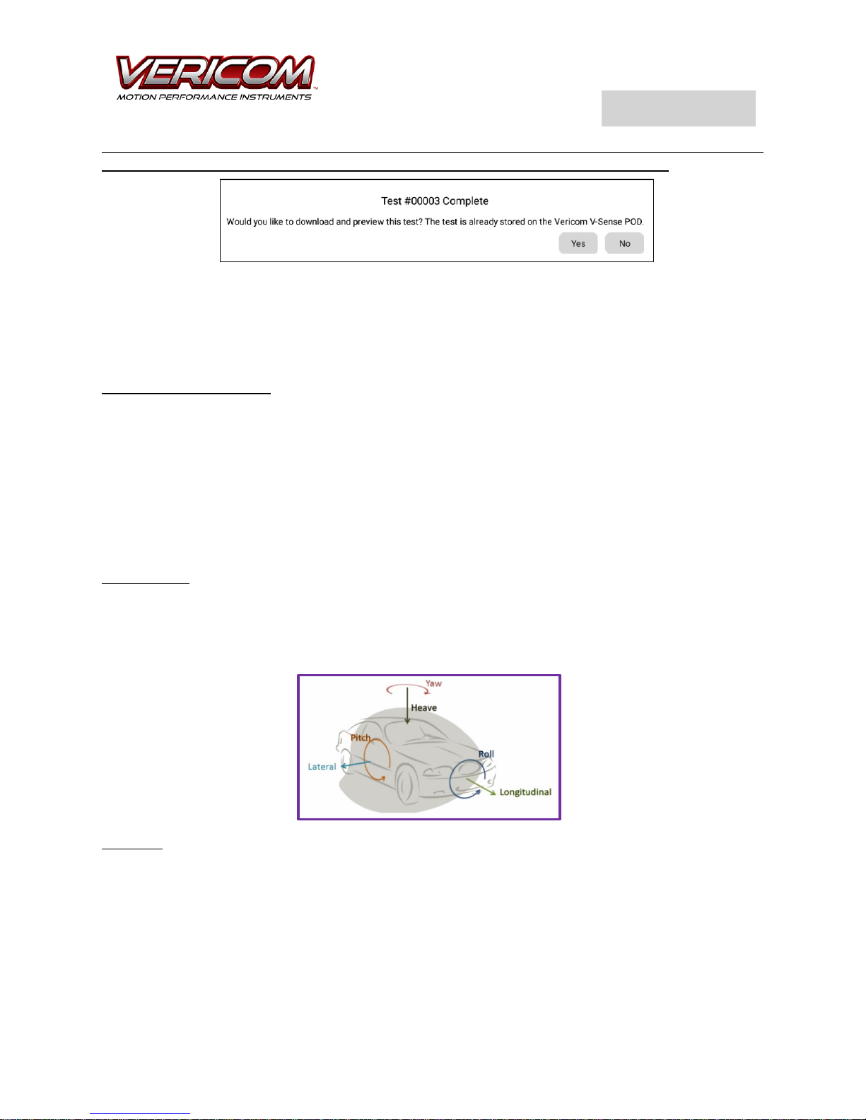
Gyro Settings: The V-Sense POD includes a 3-axis gyro that measures rotation of the test object in all
directions: PITCH, YAW, and ROLL. It is recommended that the Gyro Setting be turned on for most tests.
The Gyro data can be helpful with analysis. Since the V-Sense POD includes a capacity of 16 GB flash
memory, the primary constraint for test file size is the selection of a high Sample Rate. The Gyro data is
not large and thus it is better to leave the gyro set to ‘on’ if you have any doubts about the value of the
potential data.
GPS Data: If you want to map the test data to a satellite image of the test location, the GPS Location
setting must be ON. To save the GPS speed data, set that toggle switch to ON. To analyze the slope of a
test area, turn on the GPS Altitude data. The GPS data is collected from the available satellites at a sample
rate of 10 Hz (10 times per second). With a flash memory capability of 16 GB, there is plenty of space to
save GPS data with most tests. Again, you might want to be more careful selecting the sensors that are
set as ON when you expect to have a longer test with a higher sample rate of 1000 Hz. As an example, a
test that lasts roughly 80 seconds at 100 Hz with all sensors ON will generate a data file with 8000 data
points consuming approximately 250KB of memory. NOTE: The time on the POD is automatically updated
when it receives a good GPS signal.
 Loading...