

Vericom VC4000 Owner's Manual


Table of Contents
Table of Contents
1. INTRODUCTION ............................................................................ 1
Features .......................................................................................... 2
What it comes with ......................................................................... 3
2. OPERATION BASICS ................................................................... 4
Mounting ......................................................................................... 4
Powering up .................................................................................... 7
Display and Keypad ........................................................................ 8
Menus ........................................................................................... 10
Modes ........................................................................................... 10
Tools ............................................................................................. 13
3. ACCIDENT RECONSTRUCTION USE ....................................... 14
Initial Setup ................................................................................... 14
Get VC4000 Ready ...................................................................... 15
Measuring Drag Factor ................................................................. 18
Testing Brake Performance .......................................................... 19
Measuring Coefficient of Friction .................................................. 20
Light Impact Testing ..................................................................... 23
Avoiding False Triggering ............................................................. 25
Measuring Slope ........................................................................... 26
Acceleration Testing ..................................................................... 27
Accel/Brake Run ........................................................................... 29
4. TRANSIT USE ............................................................................. 31
Initial Setup ................................................................................... 31
Get VC4000 Ready ...................................................................... 32
Testing Brake Performance .......................................................... 35
5. ENGINEERING USE .................................................................... 37
Initial Setup ................................................................................... 37
Get VC4000 Ready ...................................................................... 37
Testing Brake Performance .......................................................... 40
Acceleration Testing ..................................................................... 42
Monitor Data ................................................................................. 45
6. TOOLS ......................................................................................... 46
Monitor Data ................................................................................. 47
Crash Mode .................................................................................. 51
Calibration Check ......................................................................... 52
Deleted Run .................................................................................. 55
SD Card Options .......................................................................... 56
Accel/Brake Runs ......................................................................... 58
Enter Suffix ................................................................................... 59

Measuring Slope ........................................................................... 60
7. VC4000 SETUP ........................................................................... 61
Setup Flowchart ............................................................................ 63
G Threshold .................................................................................. 65
Vehicle ID ..................................................................................... 65
Set Defaults .................................................................................. 66
Date/Time ..................................................................................... 67
Pitch/Roll Factors ......................................................................... 67
User Type ..................................................................................... 69
English/Metric ............................................................................... 71
RS232 Port ................................................................................... 72
Brake MPH ................................................................................... 72
Sensors Setup .............................................................................. 73
OBDII Sensors .......................................................................... 73
Analog Out ................................................................................ 74
GPS Sensors ............................................................................ 75
Accelerometer Setup .................................................................... 76
G Summation ............................................................................ 76
G Smoothing ............................................................................. 78
Zeroing On/Off .......................................................................... 79
Accelerometer Range ............................................................... 79
G Adjust .................................................................................... 79
Graph Range ............................................................................ 80
Alarm Threshold ........................................................................ 80
Performance Setup ....................................................................... 81
Vehicle Weight .......................................................................... 81
Countdown On/Off .................................................................... 82
Maintenance ................................................................................. 82
Unit Information ......................................................................... 82
Run Tests .................................................................................. 82
Discharge Battery ..................................................................... 82
8. SENSOR INPUT .......................................................................... 83
OBDII Input ................................................................................... 84
Analog Output ............................................................................... 84
GPS Input ..................................................................................... 85
External Activation ........................................................................ 86
9. REVIEW - PRINT DATA .............................................................. 90
Display a Run ............................................................................... 90
Print Runs ..................................................................................... 91
Store to SD Flash drive ................................................................ 91
10. PC INTERFACE ......................................................................... 92
RS232 Ports ................................................................................. 93

Table of Contents
USB Port ....................................................................................... 95
11. UPDATING FIRMWARE ............................................................ 96
12. CHARGING THE BATTERY ..................................................... 98
13. CUSTOMER SERVICE .............................................................. 99
Warranty ....................................................................................... 99
Repairs ......................................................................................... 99
Options, Upgrades and Accessories .......................................... 100
14. TROUBLESHOOTING ............................................................. 101
15. SPECIFICATIONS ................................................................... 103

VC4000 Manual
1
VERICOM VC4000PC
AND BRAKE METER
OWNERS MANUAL
Revision 1.8, October 2, 2013
1. INTRODUCTION
ecades of refinement make the VC4000 the best yet. The
VC4000 has been designed for ease of use and simplicity of
operation for quick and easy results, yet has advanced
features for doing much more. The unit is preprogrammed
with standard defaults so that it is ready to operate immediately. The
new VC4000 measures X, Y and Z axis acceleration, OBDII and
GPS. The more acquainted you become with the VC4000 the more
applications you will discover.
D

VC4000 Manual
2
Introduction
3-axis accelerometer
Single vacuum cup mounting
Summation of X+Y+Z vectors
Analog output of sensors or speed
Menu selection software
RS232 port
USB port
Updateable firmware via USB interface
Delete individual Runs
Battery shows charging on display and LED on front
Audible G alarm
Calculates adjusted braking distance
115 minutes of internal data storage
2GB SD flash memory card for extra storage (PC)
GPS speed and position (with GPS module) (PC)
OBDII input compatible (PC)
Selectable G range of 2 or 6 G (PC)
Profile Professional included (PC)
Can send data directly to Profile (Data Streaming) (PC)
Variable sample rate of 1, 10, 100, 500 or 1000Hz (PC)
This manual covers everything necessary to operate your VC4000.
For further information and details, see our web site
www.vericomcomputers.com and go to the support page. There
will be documents with tips on various subjects. Look to the support
pages for firmware updates for your VC4000.
How to use this manual
The gray area on the page edges allow you to quickly thumb through
to find the section you want. Use the Table of Contents at the
beginning to quickly search for the general section you are interested
in. If you can’t find what you are looking for, go to our web site’s
support pages for more detailed information. This manual covers the
VC4000 Brake Meter and the VC4000PC. When you see “(PC)”
means it applies to the VC4000PC model only.
VC4000 Features

VC4000 Manual
3
Check to see that the following items are supplied with your VC4000:
1 VC4000 with single cup mounting assembly
1 Power cord (to cigarette lighter)
1 AC wall adapter
1 USB interface cable (PC)
1 VC4000 manual
1 Profile CD (PC)
1 Carrying case
Optional Accessories:
RS232/Analog out splitter
GPS input (PC)
OBDII input (PC)
Activation switches
Reaction time switches
Portable thermal micro printer
Variety of mounting bases
Two cup mounting system
Extra carrying case
Wireless modems for up to 7 mile data transfer (PC)
What it comes with
Operations Basics
VC4000 Manual
4
2. OPERATION BASICS
This section will give you basic operating
procedures for the VC4000.
The VC4000 does not have to be level to get accurate results. It
uses a 3 axis accelerometer and calculates the vector sum of all 3
axes to calculate G force, speed and distance. G “Summation 3D
(XYZ)” must be on in Setup. It is on by default. See page 76 for
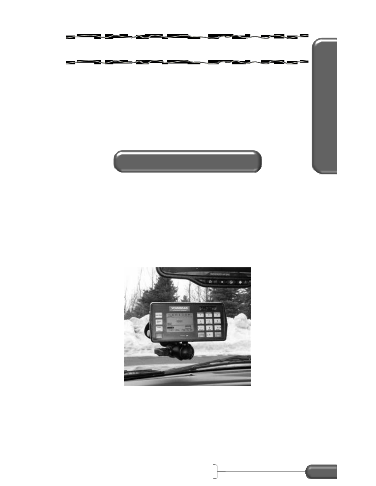
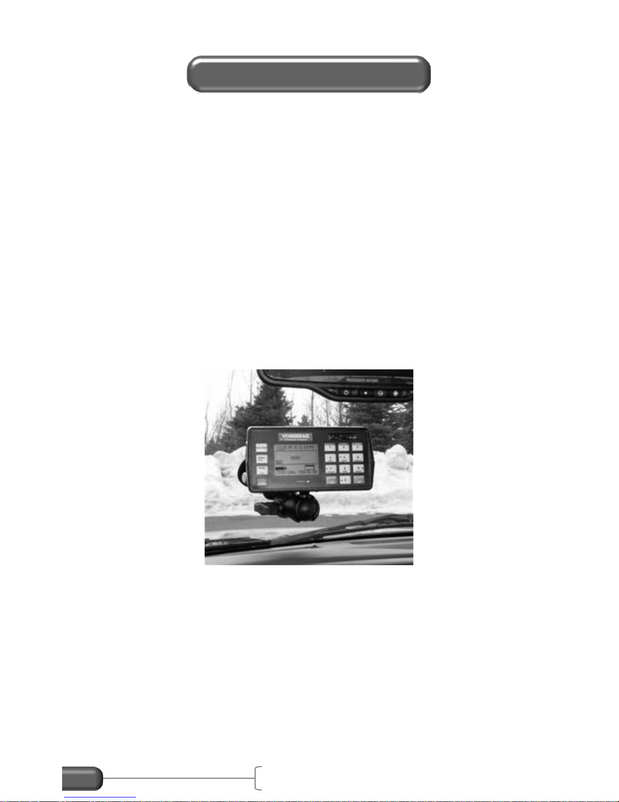
details. Mount the VC4000 so the display is roughly facing the back
of the vehicle, or so the X-axis is roughly along the front to back line
of the vehicle.
Figure 1: Single mount on windshield
Mounting
VC4000 Manual
5
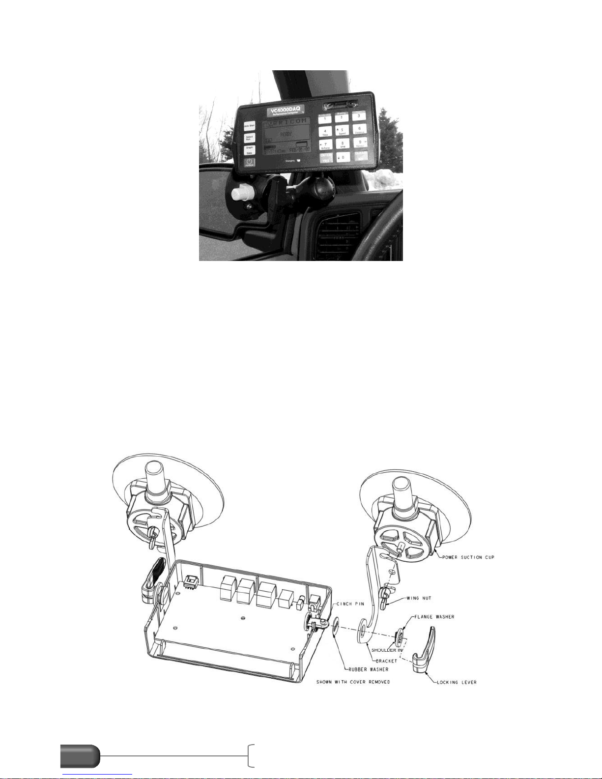
Figure 2: Single mount on side window
The VC4000 uses a single mounting arm and a pump up vacuum
cup to attach to the windshield or side window. The VC4000 and the
suction cup each have a plate with a ball that the arm attaches to.
Loosen the thumb screw on the arm and position the VC4000, and
then tighten the thumb screw to clamp the arm onto the mounting
base balls. Other mounting accessories are available. See our web
site for details.
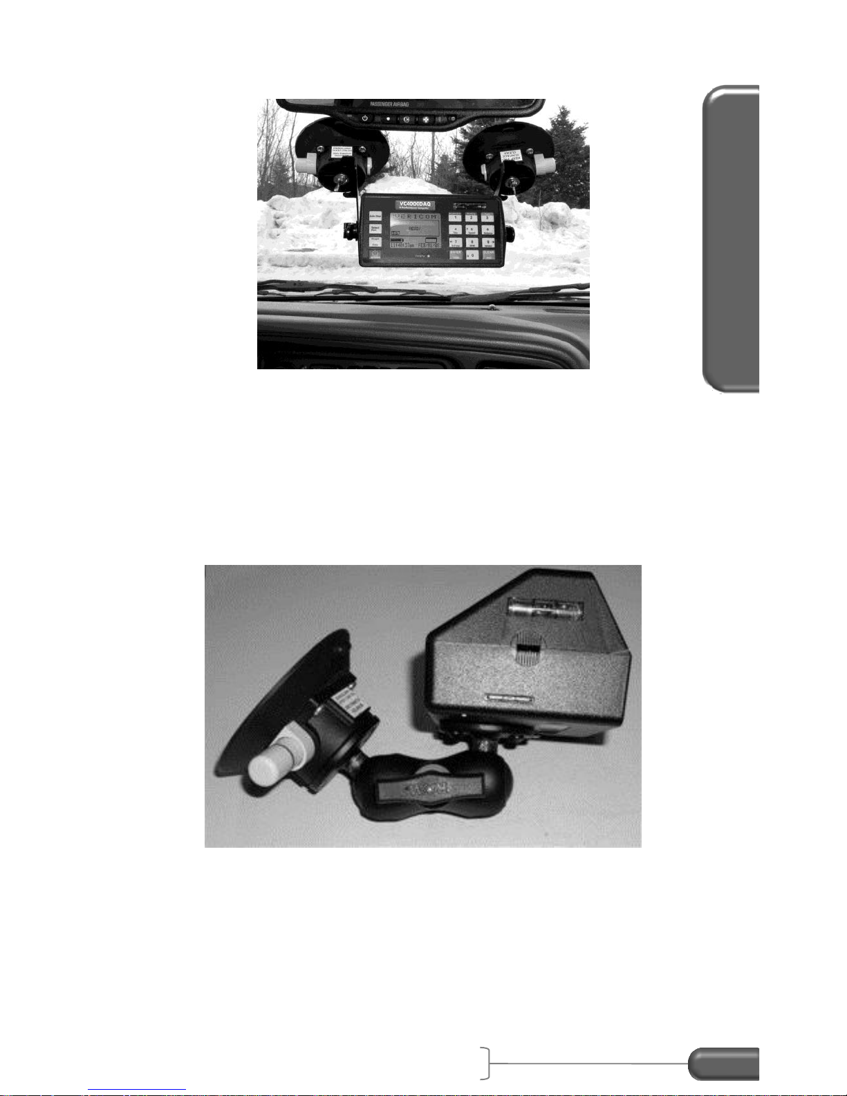
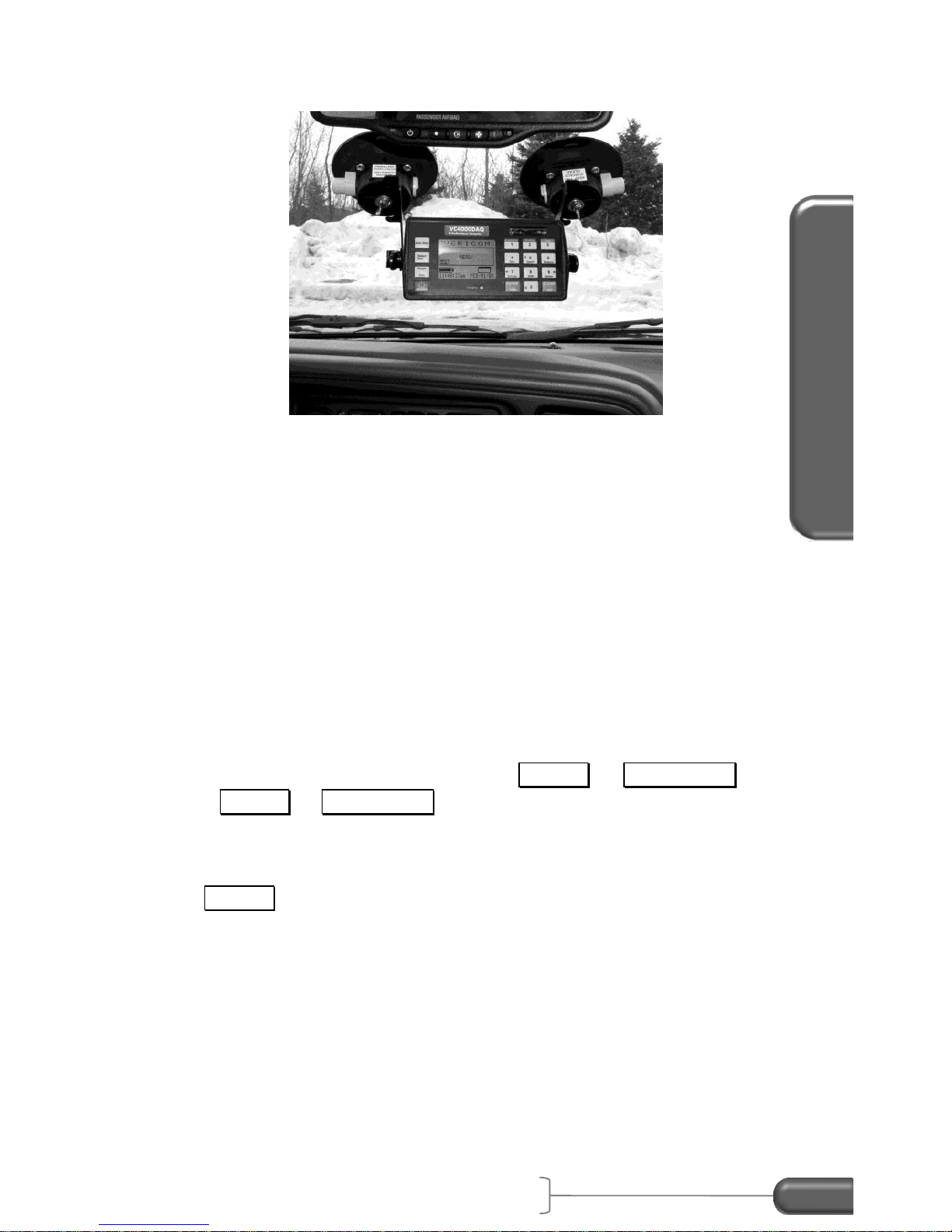
Alternatively, the VC4000 can be mounted more rigidly by using a
two suction cup kit with brackets attached to the sides of the unit.
Figure 3: Dual cup assembly
Operations Basics
VC4000 Manual
6
Figure 4: Dual cups mount
1. If you do not wish to use the batteries, plug the power cord
into the back of the VC4000 and into the vehicle's cigarette
lighter.
2. Plug external accessories such as VSI or GPS into VC4000.
See page 83 for connection description.
Figure 5: Assembly w/single vacuum cup

VC4000 Manual
7
Battery
The VC4000 has a semi-permanent internal battery pack that will
run for at least 6 hours before it needs recharging. The battery pack
can be changed by the user if it does not hold a charge anymore.
The unit can be operated from the battery or plugged into a vehicle’s
accessory jack (cigarette lighter) while testing. The battery will
charge while plugged into the vehicle. Accessories such as GPS will
discharge the battery quicker since they draw power from the
VC4000. It can also be powered and recharged from the wall
adapter. Recharging will take up to 3 hours. While charging, the
charging indicator on the front will light and if the unit is turned on the
battery gauge on the display will show arrows.
Turning on and off
Hold the power key for about 1 second to turn the unit on. To turn
the power off hold the power key for about 1 second until the unit
beeps and displays a message to release the power key.
Safety Circuit
The VC4000 has safety circuits in place for accidental shorting or
reverse polarity of sensors or power input. If a sensor draws too
much current it will shut the power off to the unit. Sometimes when a
sensor is plugged in when the VC4000 power is on the unit will shut
off due to the inrush current when the sensor first powers on. This is
why we recommend plugging in all accessories with the power off.
Static Shock
If the unit is struck with ESD (electrostatic discharge) the display may
go blank, or less likely the unit may shut off. Push a key on the
keypad to see if the display comes back. You may have to get back
to the READY screen to make the display re-appear.
Powering up
Operations Basics
VC4000 Manual
8
Display
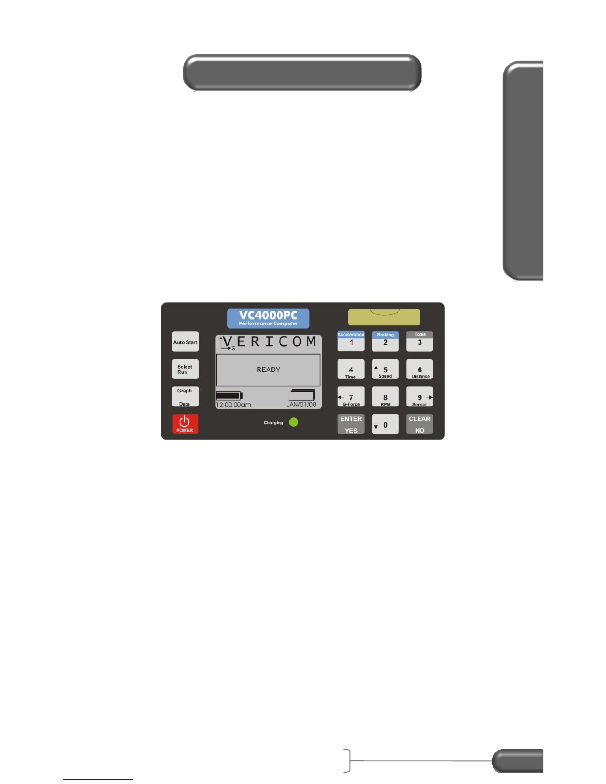
The VC4000 uses a graphic and text display. It has large letters so
it is easy to see from a distance, such as on a windshield when
viewing from the drivers’ seat. The display and keypad are lighted
for viewing in low light. The light will go out after a few minutes if a
key has not been pressed. It will light again when a key is pressed.
Keypad
The keypad has 16 keys with the numeric side laid out like an
industry standard telephone keypad.
Figure 6: keypad
Many keys have more than one function, depending on what the
display shows. See the following table.
Display and Keypad

VC4000 Manual
9
Key function table:
Key
Function
Auto Start
Press after pressing Braking or Acceleration to sense
the G-Force activation threshold.
Select
Run
Select a run from memory to display or print.
Graph
Data
While viewing a run, press to toggle between graphs
and data of run.
POWER
Hold down for 1 second to turn unit on. Hold down for
1 second to turn unit off.
1
Acceleration
Start an acceleration test or enter the numeric 1.
2
Braking
Start a brake test or enter the numeric 2.
3
Tools
Show the Tools menu or enter the numeric 3.
Time
4
Enter the numeric 4 or display a time graph.
Speed
5
Enter the numeric 5, display a speed graph or scroll up.
Distance
6
Enter the numeric 6 or display a distance graph.
G-Force
7
Enter the numeric 7, scroll the cursor left, display a GForce graph or display detailed G-Force data for an
acceleration run.
RPM
8
Enter the numeric 8, display an RPM graph or display
detailed RPM data for an acceleration run.
Sensor
9
Enter the numeric 9, scroll the cursor right or scroll
through GPS or VSI graphs.
0
Enter the numeric 0 or scroll down.
ENTER
YES
Enter information, select a menu item or respond YES
to a prompt.
CLEAR
NO
Clear memory, clear information, go back to previous
screen or respond NO to a prompt.
Operations Basics
VC4000 Manual
10
The VC4000 uses Menus when several choices are available. Use
the up and down arrows to scroll through the list. Hold down the up
or down arrow to quickly scroll through a list. The menus use wrap
around so when you reach the end of a list the cursor jumps to the
other end of the list. Press ENTER / YES to select your choice.
Press CLEAR / NO to go to the previous screen.
The VC4000 has 2 modes: Braking and Acceleration.
Braking
Use the Braking mode to test a vehicle’s brakes or measure the drag
factor of a road surface. From the “READY” screen press
2
Braking
.
Press the Braking key while at a complete stop. If the Braking key
was pressed while reviewing data from a previous test, or if the
zeroing setting was turned off, it’s not necessary to come to a
complete stop before pressing the Braking key. The VC4000 will
use the zero reference from the previous test or if zeroing was turned
off it will use the zero reference established at the factory. See page
79 in setup for more details on zeroing. The VC4000 will zero adjust
the accelerometers to the current angle the unit is facing. Press the
“Auto Start” key before accelerating up to your target speed, or press
it after you’ve reached your target speed if conditions might cause
vibration to prematurely activate the unit.
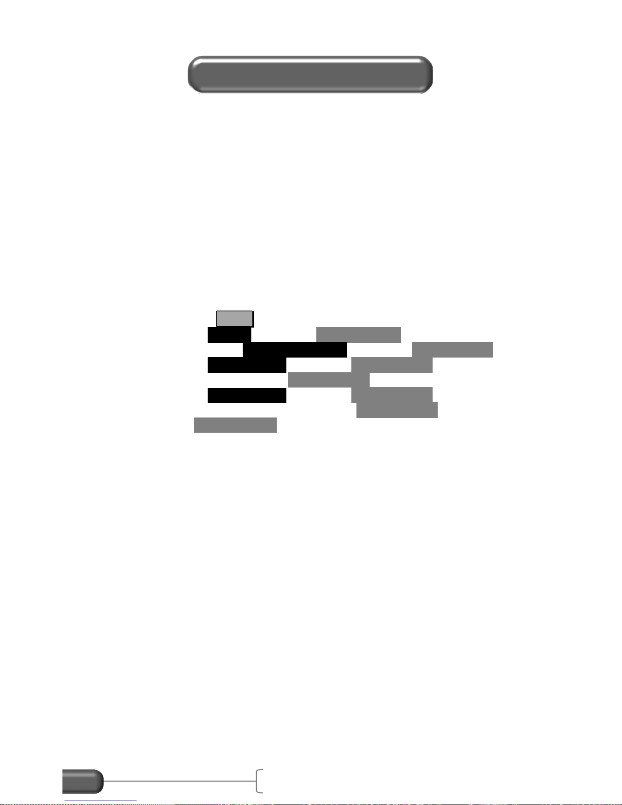
Menus
Monitor
Cal. Check
Setup
Delete Run
Print
SD Card Options
Accel/Brake Run
Crash Mode
Modes

VC4000 Manual
11
Basic steps for brake testing:
1. Connect GPS or VSI if you are using them. (PC)
2. Mount the VC4000.
3. Position the vehicle on the same incline as the test is being
performed.
4. Press the Braking key. Unit will zero adjust itself.
5. Press the Auto Start key.
6. Accelerate up to target speed.
7. Apply the brakes hard and fast and come to a complete stop.
8. Use the arrow keys to scroll through the data.
For further details see application specific sections. Note: Braking
mode always uses 100Hz sample rate regardless of what the sample
rate is set to in Setup.
Operations Basics
VC4000 Manual
12
Acceleration
Use the Acceleration mode to measure time, speed, distance,
average G and peak G during acceleration. From the “READY”
screen press
1
Acceleration
. Press the Acceleration key while at a
complete stop. The VC4000 will zero adjust the accelerometers to
the current angle the unit is facing. A menu will appear showing
some pre-defined tests and a custom choice. Choose Custom to
make your own test. You may also press the Auto Start key to
start a QuickSet™ ¼ mile test.
Basic steps for acceleration testing:
1. Connect sensors if you are using them.
2. Mount the VC4000.
3. Position the vehicle on the same incline as the test is being
performed.
4. Press the Acceleration key. Unit will zero adjust itself.
5. Select a test from the menu or Press Auto Start key for ¼
mile testing.
6. Accelerate up to the end point.
7. Use the arrow keys to scroll through the data.
If the Acceleration key was pressed while reviewing data from a
previous test, or if the zeroing setting was turned off, it’s not
necessary to come to a complete stop before pressing the
Acceleration key. The VC4000 will use the zero reference from the
previous test or if zeroing was turned off it will use the zero reference
established at the factory. See page 79 in setup for more details on
zeroing.
For further details see application specific sections.
0-30 mph
0-60 mph
0-80 mph
0-100 ft
0-300 ft
0-15 sec
Custom
AutoStart 1/4 mile
VC4000 Manual
13
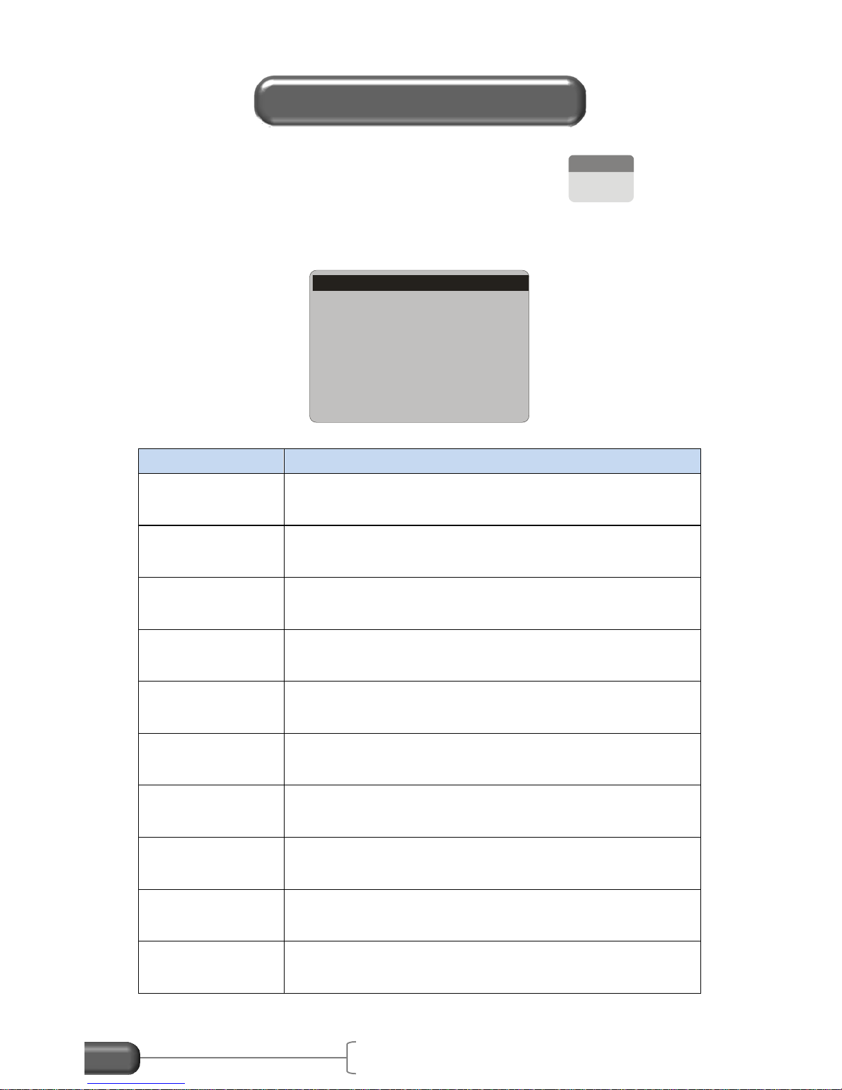
The VC4000 has several tools available. Press the
3
Tools
key to
bring up a list of available tools. Below is a list of the tools and a
short description of each tool.
Tool
Description
Monitor
Continuously display Acceleration, GPS data (PC)
or OBDII sensors (PC)
Crash Mode
(PC)
Saves data 1 second before a high G-Threshold
and up to 30 seconds after
Cal. Check
Check calibration on internal accelerometers
Setup
Change VC4000 Setup including G-Threshold,
User type and turn GPS (PC) or VSI (PC) on or off
Delete Run
Delete a run from memory
Print
Print a single or all runs in memory
SD Card
Options (PC)
Copy or erase runs from SD Card
Accel/Brake
Run
Perform an acceleration test followed by a brake
test without stopping to re-zero
Enter Suffix
Adds a suffix letter to the run file when saved
using Profile 5
Measure Slope
Measure slope of a road in Grade and Degree
Tools
Monitor
Cal. Check
Setup
Delete Run
Print
SD Card Options
Accel/Brake Run
Crash Mode
Accident Recon Use
VC4000 Manual
14
3. ACCIDENT RECONSTRUCTION
USE
This section gives specific instructions on how to
use the VC4000 in accident reconstruction.
User Type
When you first receive your VC4000 the User Type will be set
“General” which displays all available data. You should change this
setting to “Accident Reconst.” User Type. This will show all the
data necessary for the accident reconstructionist.
To change the User Type to Accident Reconstruction, follow these
steps:
1. Press the Tools key.
2. Scroll to Setup and press ENTER / YES .
3. Scroll down to User Type and press ENTER / YES .
4. Scroll up to Accident Reconst. and press ENTER / YES .
5. Press CLEAR / NO to get back to the READY screen.
Or use Profile to change the setup in the VC4000 from your PC:
1. Start the Profile program
2. Connect the VC4000 to your computer
3. Turn on the VC4000
4. In Profile, Click on the VC4000 Setup icon (VC4000 tab,
VC4000 Setup)
5. VC4000 will beep and Profile will read the setup on the
VC4000
6. Click the User Type drop down box
7. Select Accident Reconst.
8. Click the “Send Setup” key
ALL settings can be changed using Profile. Not all settings can be
changed using the VC4000 keypad.
Initial Setup
VC4000 Manual
15
Do not use this unit in violation of federal, state or local laws. For
safety reasons the driver should never press any keys on the
VC4000 while the vehicle is in motion. If observation and operation
of the VC4000 is required from a moving vehicle, use a separate
observer/passenger. Please buckle up and drive safely.
Mounting
The VC4000 does not have to be level to get accurate results. It
uses a 3 axis accelerometer and calculates the vector sum of all 3
axes to calculate G force, speed and distance. G “Summation 3D
(XYZ)” must be on in Setup. It is on by default. See page 76 for
details. Mount the VC4000 so the display is roughly facing the back
of the vehicle, or so the x-axis is roughly along the front to back line
of the vehicle.
Figure 7: Single mount on windshield
Alternatively mount the VC4000 flat and level using the single
suction cup mount or the dual bracket option with two pump-up
suction cups.
Get VC4000 Ready
Accident Recon Use
VC4000 Manual
16
Figure 8: Dual cups mount
Mounting Flat and Level
If mounting flat and level, it is not necessary to use the Z axis for
calculating the vector sum. In fact, using the Z axis may introduce
some error due to vertical vibration caused from the road surface.
Either use X or X+Y summation if mounting flat and level. Use the
bubble levels on the front and left side of the VC4000 to level it, if
your vehicle is reasonably flat and level. Within 3 degrees of level is
sufficient to get accurate data. The VC4000 must be parallel to the
road surface both longitudinally and laterally. If using X only
summation, the VC4000 must be positioned parallel to the road
surface and the X axis in line with the front to back line of the vehicle.
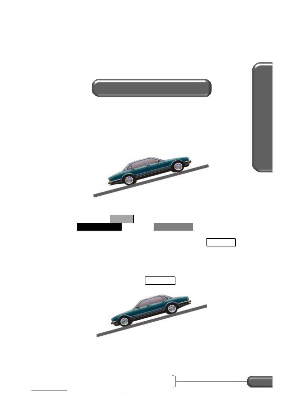
Slope of the road and zero adjusting
When performing a test the VC4000 will zero adjust itself for the
slope of the road when you press the Braking or Acceleration key.
If the Braking or Acceleration key is pressed on the same slope, the
Average G-Force (Drag Factor) given by the VC4000 will include the
grade of the road. When vehicle testing or measuring Drag Factor
the road surface does not have to be level; however, you must press
the Braking key at the same slope you are testing. This will allow
the VC4000 to compensate for slope and all data will be accurate.
When measuring coefficient of friction () you must zero adjust on a
level surface. The vehicle must be at a complete stop during zero
adjusting.
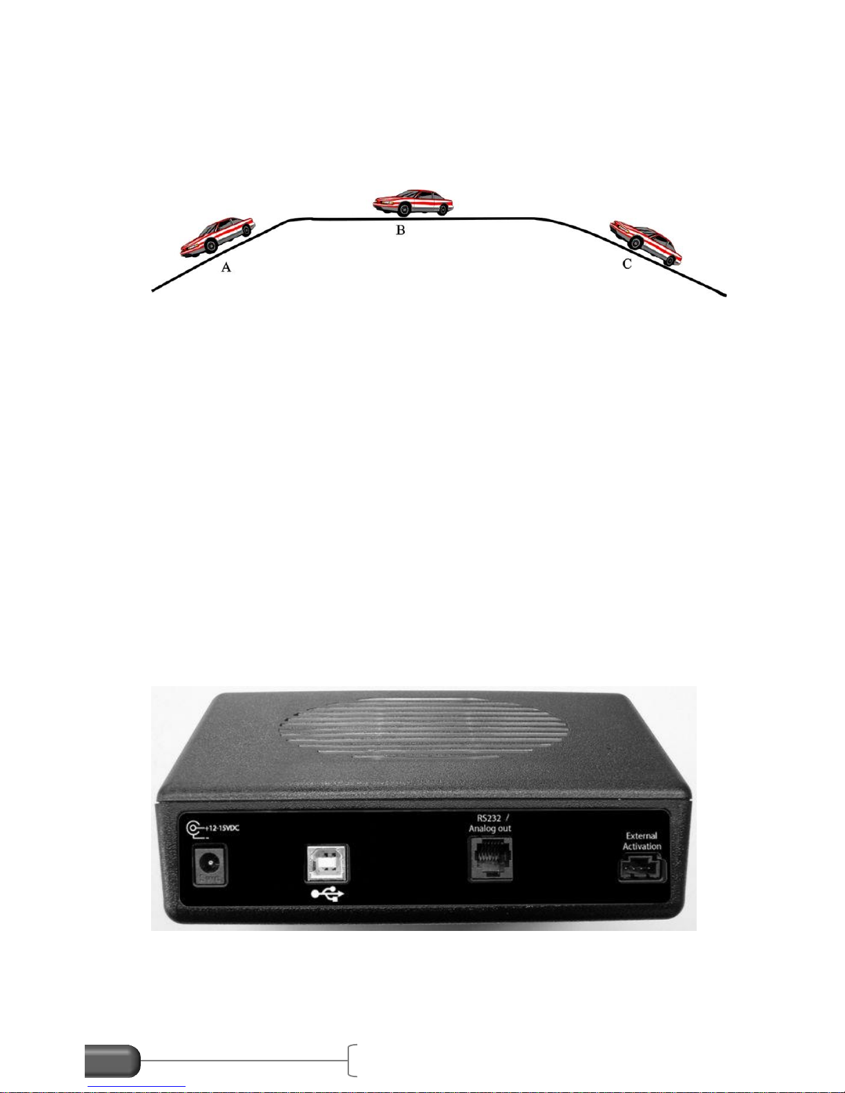
VC4000 Manual
17
Slope A = -0.1
Slope C = +0.1
Zero adjust at point B
Do skid test at point A, B or C
f = µ = 0.800
Zero adjust at point A
Zero adjust a point C
Do skid test at point A
Do skid test at point C
f = µ - slope
f = µ + slope
-0.8 (-) +0.1 = -0.7
-0.8 (+) -0.1 = -0.9
-0.8 + 0.1 = -0.7
-0.8 – 0.1 = -0.9
VC4000 will display -0.700 Ave G
VC4000 will display -0.900 Ave G
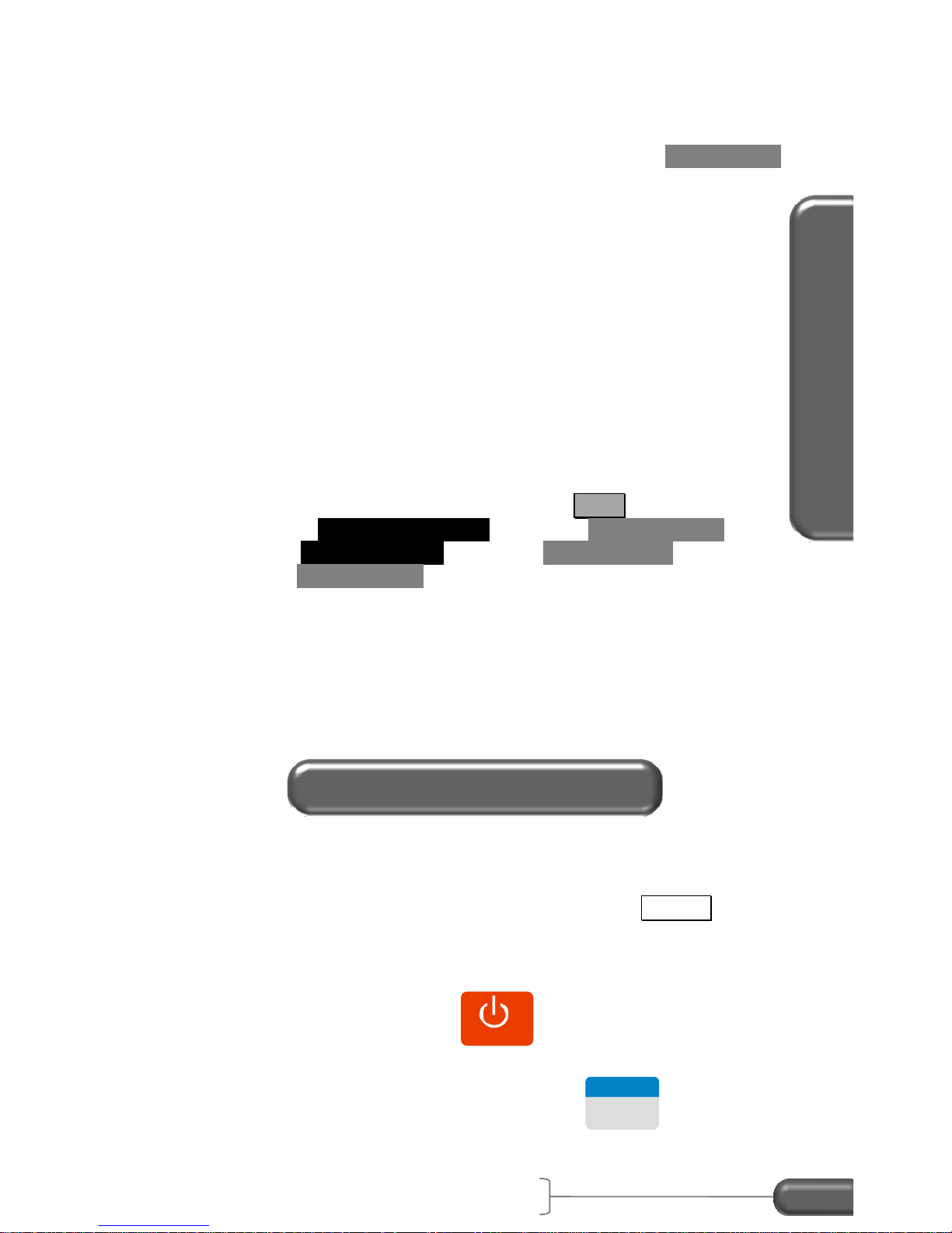
Attaching accessories
It may be easier to plug in cables before mounting the VC4000. If
you do not wish to use the batteries on the VC4000 plug the
provided power cord into back of VC4000 and into vehicle's
accessory jack if one is available. Plug the external activation
connector into VC4000 if you are using it (see page 86 for external
activation). Plug in VSI or GPS if needed (PC).
Figure 9: VC4000 back panel
VC4000 Run Storage Memory
The VC4000 stores all braking runs to internal flash memory.
Eventually the memory will fill up or the number of files will exceed
Accident Recon Use
VC4000 Manual
18
9,999. When this happens you will have to clear memory. The
display will prompt you to clear memory after the error message
appears. You should clear run data memory periodically to ensure
data storage is successful. To clear memory, press the CLEAR / NO
key from the “READY” screen and follow the prompts. Monitor and
acceleration runs can store to internal flash memory or use Data
Streaming.
(PC) Data Streaming sends the data directly to Profile without storing
it in flash memory first. It has a sample rate of 100Hz and can run
for up to 24 hours. Use Profile and click on the menu “Import/Data
Streaming” to use this feature. See Profile help or Profile manual for
more details.
(PC) The VC4000PC includes an SD flash memory card on which to
store run data. To transfer runs onto the SD flash memory card
follow these steps:
1. From the “READY” screen, press the Tools key.
2. Scroll to SD Card Options and press ENTER / YES .
3. Select Copy All Runs and press ENTER / YES .
4. Press CLEAR / NO twice to get back to the READY screen.
All runs in the VC4000PC memory will be copied onto the SD card.
The runs will remain in the VC4000PC memory until you delete
them. A typical 1GB SD card will hold over 200,000 runs.
The most common use of the VC4000 for an accident
reconstructionists is to measure Drag Factor. In the VC4000
Average Gx is the drag factor if you pressed the Braking key on
the same slope as the accident scene.
1. Drive to the area where you want to take a measurement.
2. To power on, press the
POWER
key and hold for 1 second
until the unit beeps.
3. From the “READY” screen press the
2
Braking
key with the
vehicle at a complete stop. The VC4000 will zero adjust the
Measuring Drag Factor

VC4000 Manual
19
accelerometers, show the available record time in seconds,
display the run number being saved, and then display:
4. Position the vehicle before the scene of the accident
allowing enough distance to accelerate to your desired target
speed. (As an example back up approximately 300 feet). A
typical braking test speed on dry pavement is 30 mph for
vehicles equipped with standard brakes and 45 mph for
vehicles equipment with ABS.
5. Press the
Auto Start
key. The VC4000 will display 'Auto-
Start-Ready' and the current G reading.
6. Accelerate the car to the desired initial braking speed. After
reaching the desired initial braking speed, hit the brakes
hard and fast, applying maximum brake pedal pressure until
the vehicle comes to a complete stop.
7. If you wish to do another skid test on the same slope (in the
same direction) do not press the CLEAR / NO key and the
VC4000 will retain the calibration for that grade. Press the
“Braking” key and repeat step #4.
When testing the performance of a vehicles braking system, perform
the tests on a flat and level surface. An optional brake pedal
activation switch is available if required.
1. Drive to an area that is flat and level.
2. To power on, press the
POWER
key and hold for 1 second
until the unit beeps.
PUSH
AUTO START
Testing Brake Performance

Accident Recon Use
VC4000 Manual
20
3. From the “READY” screen press the
2
Braking
key with the
vehicle at a complete stop. The VC4000 will zero adjust the
accelerometers, show the available record time in seconds,
display the run number being saved, and then display:
4. Position the vehicle before the test area allowing enough
distance to accelerate to your desired target speed. (As an
example back up approximately 300 feet). A typical braking
test speed on dry pavement is 30 mph for vehicles equipped
with standard brakes and 45 mph for vehicles equipment
with ABS.
5. Press the
Auto Start
key. The VC4000 will display 'Auto-
Start-Ready' and the current G reading.
6. Accelerate the car to the desired initial braking speed. After
reaching the desired initial braking speed, hit the brakes
hard and fast, applying maximum brake pedal pressure until
the vehicle comes to a complete stop.
7. If you wish to do another skid test on the same slope (in the
same direction) do not press the CLEAR / NO key and the
VC4000 will retain the calibration for that grade. Press the
Braking key and repeat step #4.
Drag factor (f) = coefficient of friction () ± the slope. If you wish to
measure on a slope you must zero adjust on a flat and level
surface.
PUSH
AUTO START
Measuring Coefficient of Friction
VC4000 Manual
21
1. Drive to an area that is flat and level.
2. To power on, press the
POWER
key and hold for 1 second
until the unit beeps.
3. From the “READY” screen press the
2
Braking
key with the
vehicle at a complete stop. The VC4000 will zero adjust the
accelerometers, show the available record time in seconds,
display the run number being saved, and then display:
4. Position the vehicle before the test area allowing enough
distance to accelerate to your desired target speed. (As an
example back up approximately 300 feet). A typical braking
test speed on dry pavement is 30 mph for vehicles equipped
with standard brakes and 45 mph for vehicles equipment
with ABS.
5. Press the
Auto Start
key. The VC4000 will display 'Auto-
Start-Ready' and the current G reading.
6. Accelerate the car to the desired initial braking speed. After
reaching the desired initial braking speed, hit the brakes
hard and fast, applying maximum brake pedal pressure until
the vehicle comes to a complete stop.
7. If you wish to do another skid test on the same slope (in the
same direction) do not press the CLEAR / NO key and the
VC4000 will retain the calibration for that grade. Press the
Braking key and repeat step #4.
NOTE: The Average Gx will be the Coefficient of friction (), not drag
factor because you zero adjusted on a level surface.
Information available after a brake test
Use the up 5 and down 0 arrow keys to scroll the data up and
down.
Elapsed Time (E/T): The time from when the VC4000 was
activated (see threshold page 65) until the
vehicle came to a complete stop.
PUSH
AUTO START

Accident Recon Use
VC4000 Manual
22
Speed: Speed of the vehicle when the VC4000 was
activated (see threshold page 65).
Distance: Distance the vehicle traversed during the braking
time.
Avg. Gx*: Average longitudinal G force from when the VC4000
was activated to stop.
Avg. Gy: Average lateral G force from when the VC4000 was
activated to stop.
Peak Gx: The maximum longitudinal G-Force obtained from
activation to stop and the time where it occurred.
Peak Gy: The maximum positive and negative lateral G-Force
obtained from activation to stop.
Reaction Time (R/T): The time from external trigger to the G-
Threshold. (Shows only if externally
triggered)
R/T Dist: The distance traveled during the reaction
time. (Shows only if externally triggered)
G(x.x): The instantaneous G-Force at the corresponding
time.
Graphs: Press the Graph/Data key to display graphs of the
run. Press Speed, Distance, G-Force, or Sensor.
Press the same key again to scroll through multiple
graphs, such as G-Force or Sensor.
* The VC4000's Average G force (Drag Factor) is calculated by
summing the G values and dividing by the number of samples. This
will give the same result as using velocity and time.
While reviewing the data after a braking test if the braking key is
pressed the VC4000 will start a new braking test using the zero
reference established the last time the Braking key was pressed
from the “READY” screen.
VC4000 Manual
23
Since the VC4000PC has a selectable G range of 2 or 6 G’s it can
be used for low speed impact testing. The range applies to all 3
axis’s so all axes are set to either the 2 G range or the 6 G range.
The accelerometers accuracy is degraded slightly when in the 6 G
range so speed and distance calculations might not be as accurate.
A higher sample rate may also be helpful for low speed impacts.
Choose 500Hz or 1000Hz. When using 500Hz sample rate the
number of sensors besides the internal accelerometers you can
monitor is limited to 13, and 1000Hz is limited to 10 extra sensors.
To use the 6G range for the accelerometers and 1000Hz sample
rate:
1. Press the Tools key
2. Scroll to Setup and press ENTER / YES
3. Scroll down to Accelerometer… and press ENTER / YES
4. Scroll to Accel Range and press ENTER / YES
5. Choose 6G and press ENTER / YES
6. Scroll to Sample Rate and press ENTER / YES
7. Choose 500 or 1000Hz and press ENTER / YES
8. Press CLEAR / NO twice to get back to the READY screen
Or use Profile to change the accelerometer range.
Brake Mode, Crash Mode, Acceleration Mode or Monitor may be
used for these tests.
Using Crash Mode
Crash mode automatically changes the VC4000PC setup to:
Pitch/roll factors = 0
G Range = 6g
Sample rate = 1000
GPS port = port 1
G-Threshold = 4xG-Threshold up to 4G
Any GPS or VSI sensors that are turned on will still be recorded.
Only the above changes are made during the crash mode. When
the test is finished Setup is restored to how it was previously.
Up to 10 extra sensors can be turned on and recorded using GPS
Speed and VSI sensors. The VC4000PC will record at least one
Low Speed Impacts (PC)

Accident Recon Use
VC4000 Manual
24
second before impact (4xG-Threshold) and up to 30 seconds after
impact. See Tools/Crash Mode on page 51 for more information.
1. Drive to the area where you want to take a measurement, or
close, where the slope is the same.
2. To power on, press the
POWER
key and hold for 1 second
until the unit beeps.
3. From the “READY” screen press the Tools key, then select
Crash Mode with the vehicle at a complete stop. The
VC4000 will zero adjust the accelerometers, show the
available record time in seconds, display the run number
being saved, and then display:
4. Accelerate the car to the desired initial speed. After
reaching that speed, trigger the VC4000 using the external
trigger or it will activate when it impacts an object and
generates 4xG-Threshold or more.
Using Monitor
1. Drive to the area where you want to take a measurement, or
close, where the slope is the same.
2. To power on, press the
POWER
key and hold for 1 second
until the unit beeps.
3. From the “READY” screen press the Tools key, then select
Monitor, then G-Force.
4. The display will show:
5. With the vehicle at a complete stop press ENTER / YES.
The VC4000PC will zero adjust the accelerometers, show
the available record time in seconds, display the run number
being saved, and then display accelerometer data.
6. Perform your test. Press CLEAR / NO to stop saving data.
AUTO START READY
SAVE IN FILE
MEMORY?
DEPRESS YES or NO

VC4000 Manual
25
Using Brake Mode
NOTE: The VC4000PC in brake mode will stop recording data when
the acceleration is positive again. So during the impact if the
accelerometer senses positive acceleration it will end the test. In
brake mode the sample rate is always 100Hz.
1. Drive to the area where you want to take a measurement, or
close, where the slope is the same.
2. To power on, press the
POWER
key and hold for 1 second
until the unit beeps.
3. From the “READY” screen press the
2
Braking
key with the
vehicle at a complete stop. The VC4000 will zero adjust the
accelerometers, show the available record time in seconds,
display the run number being saved, and then display:
4. Press the
Auto Start
key. The VC4000PC will display 'Auto-
Start-Ready' and the current G reading.
5. Accelerate the car to the desired initial braking speed. After
reaching the desired initial braking speed, trigger the
VC4000PC using the external trigger or tap the brakes hard
enough to break the G-Threshold (0.200 default). Then
impact the object.
NOTE: Be sure to set the G Range back to 2G for other types of
testing so speed and distance are more accurate.
If you are testing a motorcycle or large truck that decelerates by
more than the default 0.200G threshold when shifting or lifting from
the accelerator, to avoid false triggering of your braking run, you may
press the Auto Start key any time after zero adjusting. For example,
you may press Auto Start after the vehicle has reached the desired
braking speed and before applying the brakes. If it’s not possible to
PUSH
AUTO START
Avoiding False Triggering
Accident Recon Use
VC4000 Manual
26
press a key while moving, increase the G-Threshold to 0.300. See
Setup, G-Threshold on page 65. The acceleration mode may be
used also. Perform a timed test for 10 seconds or the desired time
to complete the test. See Acceleration testing on the next page.
The Grade, or Slope, of the road can be very accurately measured
using the VC4000. Use the built in Measure Slope tool to measure
the slope in Percent Grade and in Degrees.
Measure the slope
1. Drive to the slope you want to measure, facing directly uphill.
2. Press the Tools key. Scroll to the bottom of the list,
Measure Slope and press ENTER / YES.
3. With the vehicle at a complete stop press the Auto Start key.
The VC4000 will zero adjust the accelerometers then show
“Position Downhill”.
4. Now turn the vehicle 180 degrees so it is facing directly
downhill and press the Auto Start key again. The VC4000
will read the acceleration then display the Slope values.
Measuring Slope
 Loading...