

Page 1
Veria Control
B35/B45
Installation guide
Page 2
- 2 - - 3 -
Table of content 1.1 Technical Specications
1 Introduction 2
1.1 Technical Specications 3
1.2 Safety instructions 5
2 Mounting instructions 6
3 Settings 10
3.1 Temperature settings 10
4 Warranty 12
1. Introduction
Veria Control B35/45 is a electronic thermostat provided with
a 2-pole switch and a oor sensor to measure and control the
desired oor temperature. The thermostat is intended for
ush-mounting.
Veria Control is equipped with a LED indicator showing
standby periods (green light) and heating periods (red light).
The maximum temperature setting of the Veria Control B35
Thermostat is 35°C, which makes it ideal for controlling
electrical heating mats beneath or on top of wood oors such
as parquet or laminates.
The Veria Control B45 Thermostat can be used for
temperatures up to 45°C, which makes it ideal for controlling
electrical heating mats on top of concrete or screed oors or
underneath a tile or decorative stone covering.
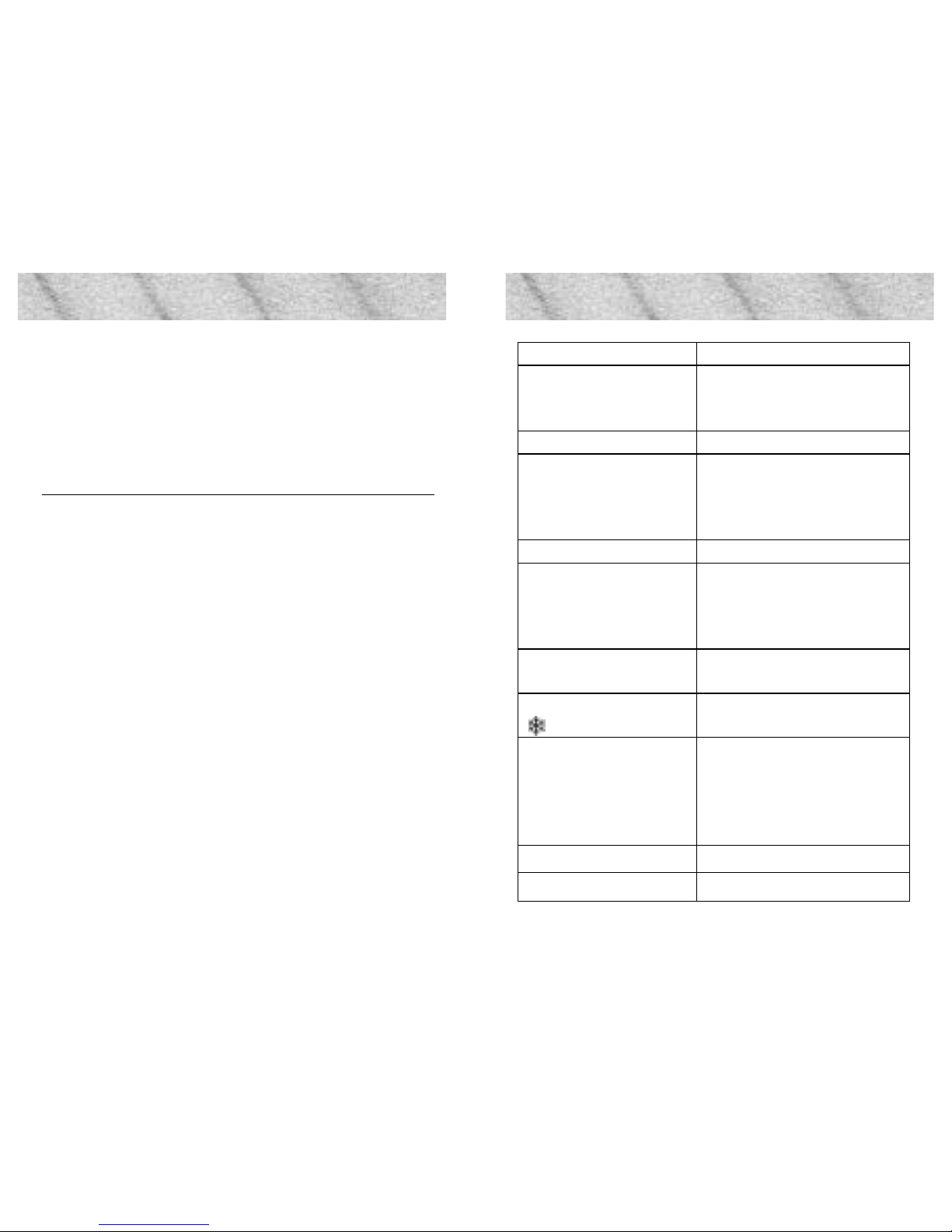
Operating voltage 180-250 VAC, 50/60 Hz
Contact rating:
- resistive load
- inductive load
250V ~ 15A/3450W
cos ϕ = 0,3 Max. 4A
Sensor NTC 15 kOhm at 25° C
Sensor values:
18°C
20°C
22°C
19,7 kOhm
18,0 kOhm
16,8 kOhm
Switching differential ±0,2° C
Temperature range:
- Veria Control B35
- Veria Control B45
(0) 15-35° C
(0) 5-45° C
Ambient temperature
range
-10º to +30° C
Frost protection
(
)
15º C (B35) / 5º C (B45)
Led Indicator:
- No light
- Red light
- Green light
- Green light ashing
Thermostat off.
Heating mat/cable is active
The desired set point tempe-
rature has been reached.
Floor sensor is faulty
Protection rating IP 31
Dimensions & weight 85mm x 85mm & 90 g
Page 3
- 4 - - 5 -
1.1 Technical Specications
Cable specication max. 1x4mm² or 2x2,5mm²
Ball pressure temperature 75°C
Pollution degree 2 (domestic use)
Type 1C
Storage temperature -20 to +65°C
Protection class
Class II -
The product complies with the EN/IEC Standard “Automatic
electrical controls for household and similar use”:
• EN/IEC 60730-1 (general)
• EN/IEC 60730-2-9 (thermostat)
Produced for:
Veria ApS
Ulvehavevej 44
DK-7100 Vejle
Denmark
1. Safety Instructions
Make sure the mains supply to the thermostat is turned off
before installation.
IMPORTANT:
When the thermostat is used to control a oor heating
element in connection with a wooden oor or similar material,
always use a oor sensor and never set the maximum oor
temperature to more than 35°C.
Please also note the following:
• The installation of the thermostat must be done by
an authorized and qualied installer according to local
regulations.
• The thermostat must be connected to a power supply
via an all-pole disconnection switch.
• The sensor is to be considered as live voltage. Have this
in mind if the sensor must be extended.
• Always connect the thermostat to continuous power
supply.
• Do not expose the thermostat to moisture, water, dust,
and excessive heat.
1.2 Safety Instructions
Page 4
- 6 - - 7 -
2. Mounting Instructions
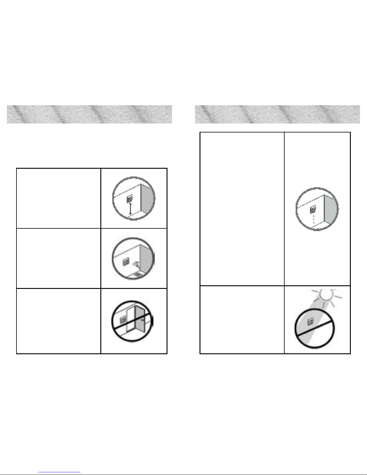
Please follow the below guidelines when installng the thermostat
Place the thermostat at a suitable height on the wall (typically 80-170cm)
In wet rooms, place the thermostat according to local regulation on IP classes.
Plaats de thermostaat niet aan
de binnenzijde van een buitenmuur.
A oor sensor enables a more accurate temperature control and is
recommended in all oor heating
applications and mandatory under wooden oors to reduce the
risk of over-heating the oor.
• Place the oor sensor in a
conduit in an appropriate
place where it is not exposed to sunlight or draft
from door openings.
• Equally distant and >2cm
from two heating cables.
• The conduit should be
ush with the oor surface - countersink the conduit if necessary.
• Route the conduit to the
connection box.
• The bending radius of
the conduit must be min
50mm.
Avoid placing the thermostat in
direct sunlight
2. Mounting Instructions 2. Mounting Instructions
Page 5
- 8 - - 9 -
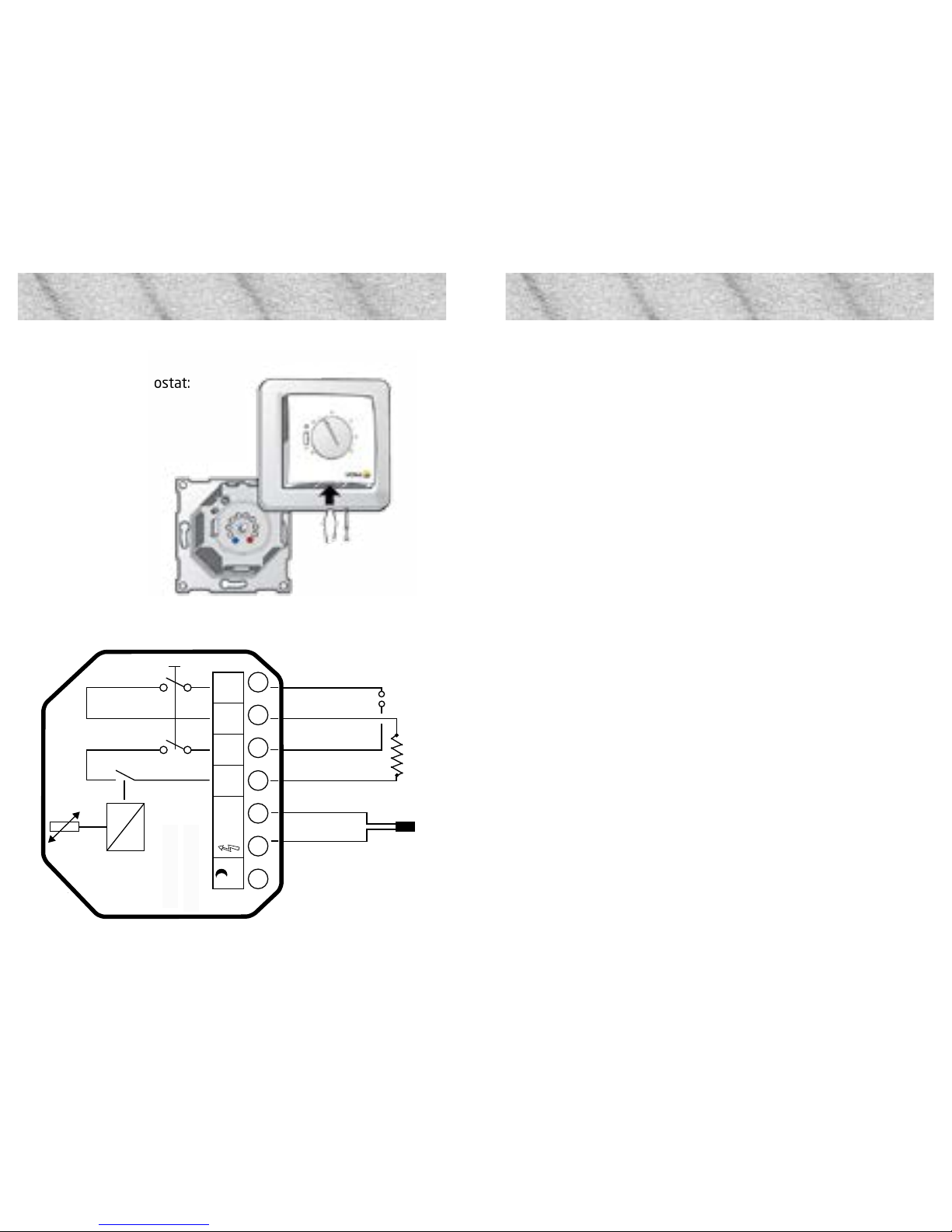
2. Mounting Instructions
Follow the steps below to mount the thermostat:
1. Open de thermostat:
2. Connect the thermostat according to the below diagram.
The screen of the heating cable must be connected to the
earth conductor of the power supply cable by using a separate
connector.
Note: Always install the oor sensor in a conduit in the oor.
3. Mount and reassemble the thermostat.
• Fasten the thermostat to a socket or an exterior wall
box by driving the screws through the holes in each
side of the thermostat.
• Install the frame and front cover in the reverse order of
disassembly.
4. Turn on the power supply
2. Mounting Instructions
L
15 A
Max.Load
NC
N L
5-45°C
N
NTC
L
LOAD
LOAD
N
L
C T N
15-35° C (B35)
Max.
15A
Floor sensor
5-45° C (B45)
Page 6
- 10 - - 11 -
3. Settings
3.1 Temperature settings
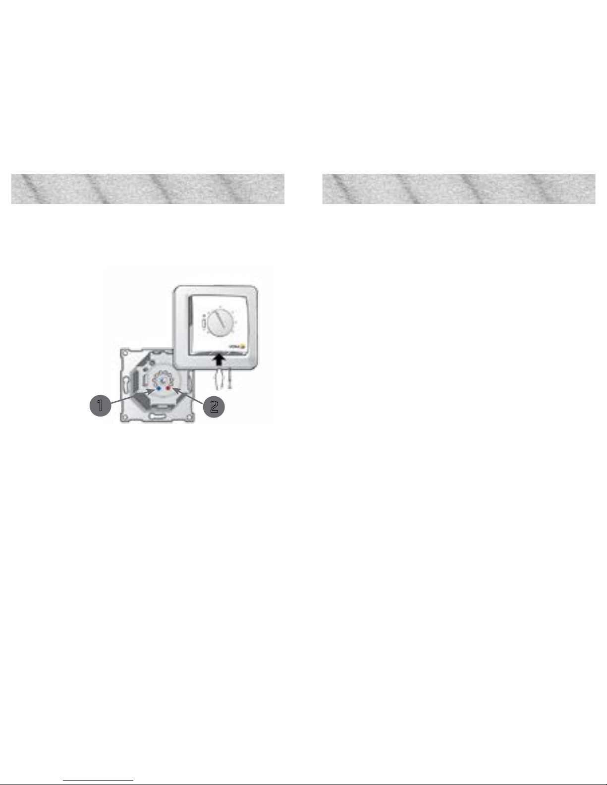
How to change the minimum and maximum oor temperatures
1. Remove the adjustment button.
2. Move the pins to the desired positions. (1 en 2)
3. Put the adjustment button back in place.
Note: Please be aware of the following:
• The oor temperature is measured where the oor
sensor is placed.
• The temperature of the bottom of a wooden oor can
be up to 10 degrees higher than the top.
• Floor manufactures often specify the max temperature on the top surface of the oor (usually 27-28˚C).
• Always use a oor sensor to control oor heating.
• Without a oor sensor, the temperature control may be
less accurate and you risk overheating the oor.
3. Settings
1
2
Page 7

- 12 - - 13 -
4. Warranty 4. Warranty
Veria products are designed for many years of trouble-free operation. Consequently, the Veria Quickmat and Veria Flexicable
products are guaranteed for 12 years if installed properly in
accordance with the Installation Guide.
All other Veria products, including the Veria Control B35/B45,
have a two-year guarantee. This guarantee covers all products
that are clearly defective due to a deciency in manufacturing,
design or material.
The guarantee is null and void in the following cases:
• If the product is not installed in accordance with the
Installation Guide.
• If the product is not connected by an authorised electrician or electrical specialist.
• If the defect is caused by an unsuitable or poor oor
construction.
In addition, guarantee claims will only be honoured if the attached guarantee certicate is completed properly. The owner
must keep this certicate in a safe place and present it in case
of a guarantee claim.
If for some reason a guarantee claim is necessary, we will
repair the product at no charge or send you a replacement
product at no charge.
The guarantee does not cover indirect or additional costs, such
as the cost of determining the cause of the fault, removing the
product, repairing the oor, etc.
Warranty certificate
Electrical installer:
Thermostat type:
Installation date:
Article code:
Stempel:
Stamp:
Note!
You must complete the following questionnaire fully and
accurately in order to make a guarantee claim.
Name:
Telephone:
Street addres:
City/town and postcode:
Page 8
- 14 - - 15 -
Notes Notes
 Loading...