

Page 1
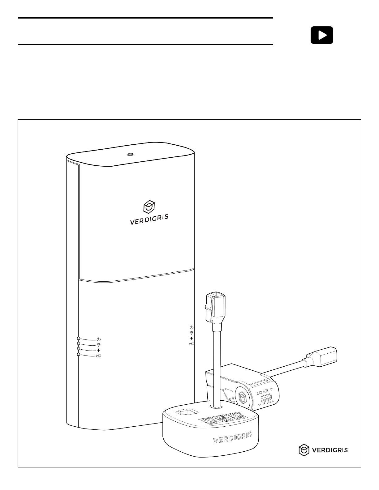
How to Install Verdigris EV2
Welcome! This manual will guide you on how to install your new system. If you need
direct assistance, call our support line at 1-844-837-3447 or email [email protected].
WARNING: Installation of Verdigris EV2 should only be performed by a licensed
electrician. You should consult your local inspector for compliance with electric codes.
If the equipment is used in a manner not specified by the manufacturer, the protection
provided by the equipment may be impaired.
Check out our install videos:
installEV2.verdigris.co
Page 2

Verdigris for Commercial and Industrial Buildings ........................................................................................................................
Technical Specifications .....................................................................................................................................................................
Energy Data Gateway .....................................................................................................................................................................
Data Transmission ...........................................................................................................................................................................
Current Transformers (CTs) ............................................................................................................................................................
Symbols on Equipment ..................................................................................................................................................................
Component List (Provided by Verdigris) .................................................................................................................................................
Tools Required ....................................................................................................................................................................................
Tools ..................................................................................................................................................................................................
Parts ..................................................................................................................................................................................................
Recommended Voltage Tap Cables for Specific Panel Voltage Configurations......................................................................
Prepare Installation ............................................................................................................................................................................
Determine Panel Type .....................................................................................................................................................................
Select Mounting Location ...............................................................................................................................................................
Select Breakers For Voltage Tap ....................................................................................................................................................
Install Voltage Tap ..............................................................................................................................................................................
For Single-Phase Panel ...................................................................................................................................................................
For Split-Phase Panel .......................................................................................................................................................................
For Three-Phase Panel .....................................................................................................................................................................
Wire The Neutral ..............................................................................................................................................................................
Connect Voltage Cables to Energy Data Gateway ......................................................................................................................
Install and Connect CTs .....................................................................................................................................................................
Select Appropriate CTs ……………………………………………………………………………………………………………….
Verify CT Install Location .................................................................................................................................................................
Install CTs ..........................................................................................................................................................................................
Large CTs & Verdigris High Current CT Interface Module .........................................................................................................
Connect Multiple CTs .....................................................................................................................................................................
Connect Multiple Verdigris High Current CT Interface Modules ..............................................................................................
Connect CTs …………………………………………………………………………………………………………………………….
Connect CTs to the Energy Data Gateway ...................................................................................................................................
Installations Using Only CT Chains ...........................................................................................................................................
Installations Using Only High Current CT Interface Modules ................................................................................................
Installations Using CTs and High Current CT Interface Modules ..........................................................................................
System Chain Check ..........................................................................................................................................................................
Check the CTs .................................................................................................................................................................................
Chain Check ....................................................................................................................................................................................
Powering Energy Data Gateway ....................................................................................................................................................
Clean Up and Close the Panel ......................................................................................................................................................
Setup & Commission Energy Data Gateway ………………………………………………………………………………………..
Error Codes .........................................................................................................................................................................................
Future Panel Modifications ……………………..……………………………………………………………………………...………
Table of Contents
3
4
4
4
4
4
5
6
6
6
6
7
7
7
8
9
9
9
9
9
10
11
11
11
11
12
13
13
14
15
15
16
17
18
18
18
19
19
20
21
22
Page 3
Verdigris for Commercial and Industrial Buildings
The intended use of Verdigris hardware systems is to monitor any motor control centers,
distribution panels, or electrical panels in any building.
Breaker Panel Types Served
EV2 advanced energy meters work with a range of
electricity mains, sub-panels, MCCs, and breaker boxes.
The Energy Data Gateway mounts external to the monitored
breaker panel, or on a nearby wall or junction box.
• Panel and voltage types (up to 42 breakers/panel):
Single-phase 100-277 V
Split-phase 100-277 V
Three-phase 120/208 V
Three-phase 240/416 V wye
Three-phase 277/480 V wye
Three-phase 120/240 V delta
Three-phase 480 V delta
Three-phase 600 V wye
Three-phase 600 V delta*
*600 V Delta metering requires an optional external power adapter.
• Frequency: 50-60 Hz
• Current measurement range (Amperage): 0.25 A–15,000 A
Data Available to You
Your high resolution data is transmitted securely via 4G
LTE, WiFi or Ethernet, stored on the cloud, and is
available 24/7 from any desktop web browser. You can
also download a csv of your data, integrate via BACnet
IP or Modbus TCP, or connect to our API at anytime.
*Data On-Premise also available for Enterprise purchase plans. Talk to a
solutions architect.
• Precision: 10 mW
• Sampling frequency: up to 7.68 kHz
• Data access via API: unlimited
• Historical data store and availability on the web:
1-minute: forever
15-minute: forever
1-hourly: forever
Daily: forever
3
Major Steps for Installation and Commissioning
Getting a Verdigris EV2 up and running consists of two parts: installation and commissioning.
Both parts must be completed successfully for data to be monitored and accessible.
A. Installation
1. Prepare Installation
2. Mount Energy Data Gateway
3. Install Voltage Tap
4. Install and Connect CTs
5. System Checks & Clean Up
B. Setup, Connect and Commission Energy Data Gateway
Follow this instruction manual for both parts A and B.
Page 4
4
Technical Specifications
Energy Data Gateway
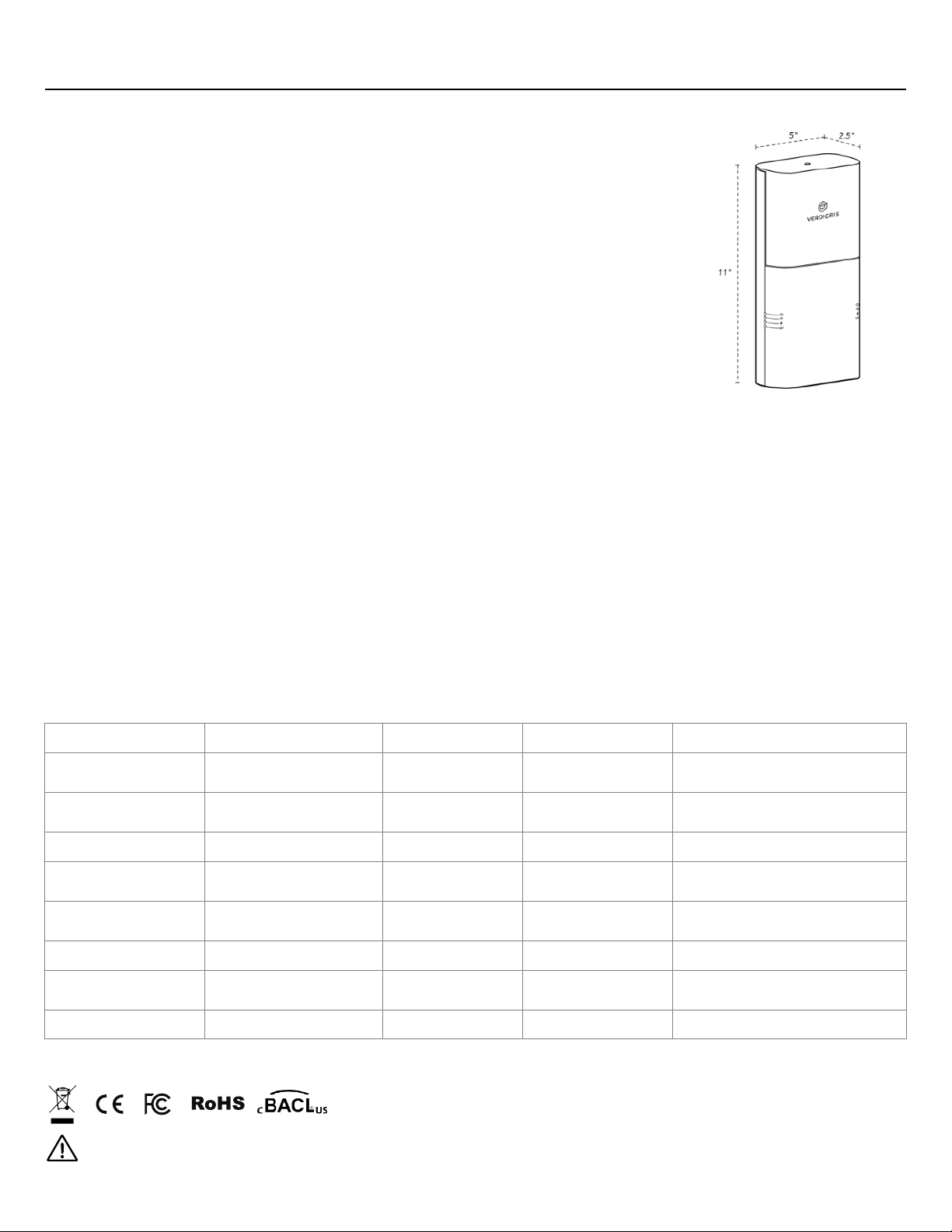
• Physical Size and Weight: 11 x 5 x 2.5 inch [280 x 127 x 64 mm], 2 kg
• Voltage Range: 100-480 VAC CAT III (CAT III-rated instruments are primarily used on fixed installations,
distribution boards, and circuit breakers and can withstand the specified voltage range.)
• Frequency Range: 50-60 Hz
• Current Rating: 300 mA
• BACnet / Modbus supported
• Cable Max Voltage: 600 V
• Temperature Range: -40 °F–158 °F [-40 ℃–70 ℃]
• ADC Accuracy: 16-bit
• Power Supply: 100-480 Vac 50/60 Hz, 20 W
• Degree of Protection: IP30
Data Transmission
• Ethernet: 100/1000 Mbps (RJ-45)
• 4G/LTE Cat 4 and LTE Cat M1/NB-loT
• Bands 3,4,8 and 13 (US and China, for more Band support inquire with your account representative.)
• WiFi: 802.11 b/g/n
• Local Networks: BACnet/IP, Modbus/TCP
• NBioT
Current Transformers (CTs)
We offers two types of CTs: (1) Verdigris Smart CTs for censor individual circuit breakers (< 60 A) in
tight spaces and (2) High Current CTs (Hinged or Coils) for larger amperage circuits. High Current
CTs connect to the data chain using the Verdigris High Current CT Interface Module adapter.
Verdigris Smart CT
Hinged CT
Coil CT
Verdigris High Current CT Interface Module
Max Circuit Ampacities
60 A per circuit
250A
Up to 15,000A per circuit
(custom sizes available)
Minimum Load
(Amperage or %)
0.25 A
0.5% of CT load
5 A
Sensor Accuracy
±2%
0.5%
0.5%
Physical Dimensions
2.2 x 1 x 1 in
[56 x 25 x 25 mm]
2 x 2.76 x 1.52 in
[50 x 70 x 39 mm]
Diameter is 0.61 in
[15.5 mm]
2.4 x 2.4 x 1 in
[60 x 60 x 25 mm]
CT Accuracy Range
(% of rated current)
1%—100%
10%–120%
0%–100%
Temperature Range
-40 °F—158 °F [-40 ℃—70 ℃]
5 °F—140 °F [-15 ℃—60 ℃]
-4 °F—158 °F [-20 ℃—70 ℃]
Max Conductor Size
4 AWG [21.1mm²]
1 in window for up to 900
kcmil or MCM [456 mm²]
4 in or 7 in window
2.4 x 2.4 x 1 in [60 x 60 x 25 mm]
Max Wire Size
Including insulator 2.3 in [58.6mm]
Varies by amperage
23.62 in [600mm]
Symbols on Equipment
De-energize Verdigris system before accessing field wiring compartment.
Page 5
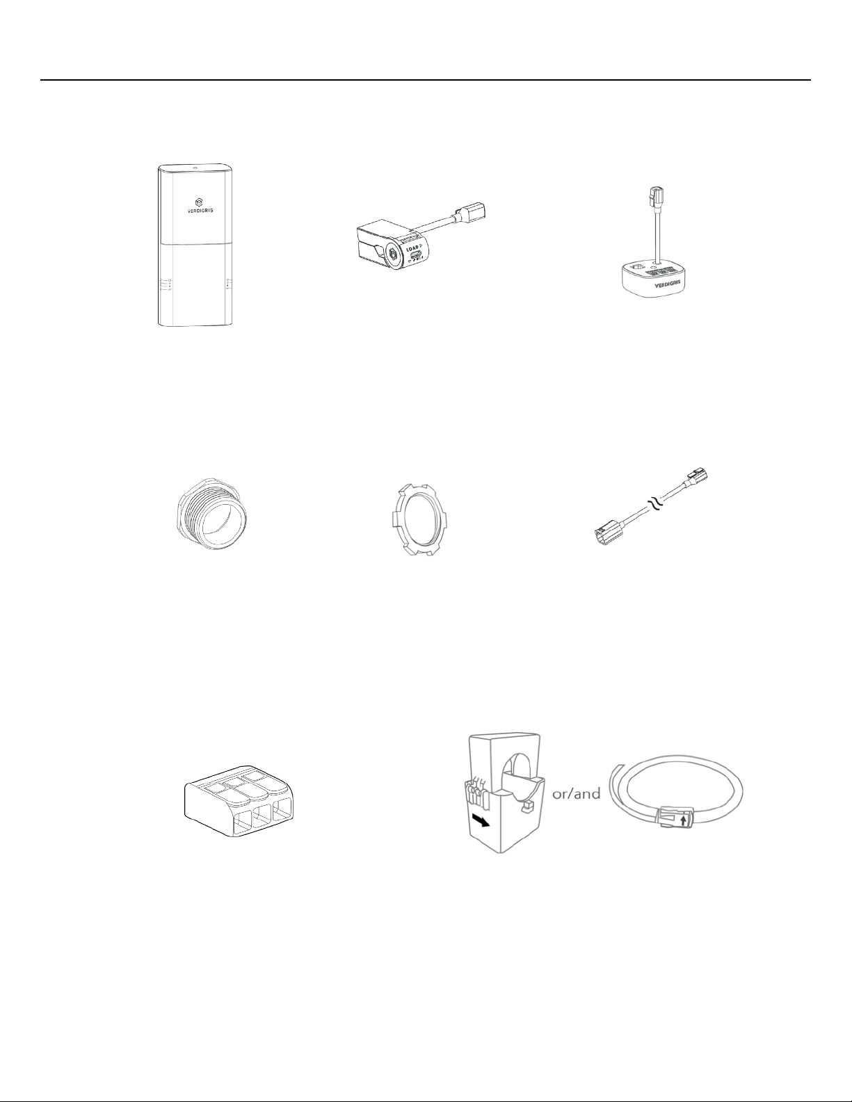
Component List (Provided by Verdigris)
5
Verdigris Smart CT
(Up to 42x per system)
Energy Data Gateway
(1x per system)
200mm, 1m, 3m CT
Chain Extension Cables
(4x per system)
Verdigris High Current CT Interface Module
*Only for wire sizes greater than 6 AWG
and/or ampacities greater than 60A
(Up to 14x per system)
Large CT (Hinged CT or/and Coil CT)
*Only for wire sizes greater than 4 AWG
and/or ampacities greater than 60A
(Up to 42x per system)
1” Locknut
(1x per system)
1” Chase Nipple
(Up to 1x per system)
Splicing Connector
*Only for three-phase, 3 wire, 480 V delta
electrical configuration
(1x per system)
Page 6
Tools Required
For all installations, you will need the following tools in addition to Verdigris components:
Tools
• Wire stripper
• Screwdrivers, including PH-2, SL-2, S-2 (needs may vary based on size of panel screws)
• Impact drill (to open the panel)
• Power drill with hole cutter (¾” or 1”) or knockout punch set (¾” or 1”)
• Hammer (used with screwdriver to punch prefabricated knockouts)
• Drywall saw (for recessed panels only)
• Colored electrical tape & marker (for labeling voltage tap breakers, specific to panel
phase color coding)
• 5 V AC plug adapter with a 5.5 mm barrel jack (to power system on independent of
voltage taps)
Parts
• Colored cables
• Cable ties (up to 25 per panel)
• Wire nuts (size dependent on size of panel breaker wires to be tapped)
• 2-¾” flex conduit connectors (for recessed panels only)
• ¾” flex electrical conduit (for recessed panels only)
Recommended Voltage Tap Cables for Specific Panel Voltage Configurations
OPTION 1: Single-phase 120/240V panels, YOU WILL ALSO NEED:
• 12 gauge wire in black and white.
OPTION 2: Split-phase 120/240V panels, YOU WILL ALSO NEED:
• 12 gauge wire in black and red, and white wire for neutral.
OPTION 3: Three-phase 120/208V panels, YOU WILL ALSO NEED:
• 12 gauge wire in black, red, and blue, and white wire for neutral.
OPTION 4: Three-phase 277/480V wye panels, YOU WILL ALSO NEED:
• 12 gauge wire in brown, orange, and yellow OR black wire with colored tape (brown,
orange, and yellow) to label the wire phases appropriately. You also need white wire
for neutral.
OPTION 5: Three-phase, 3 wire 480 V delta panels:
• 12 gauge wire in brown, orange, and yellow OR black wire with colored tape (brown,
orange, and yellow) to label the wire phases appropriately. Neutral will be served with
brown (phase A).
• Splicing connector included in component list.
IMPORTANT
Cables selected should be UL rated to 600V.
6
Page 7
Prepare Installation
Determine Panel Type
Select Mounting Location for the Unit
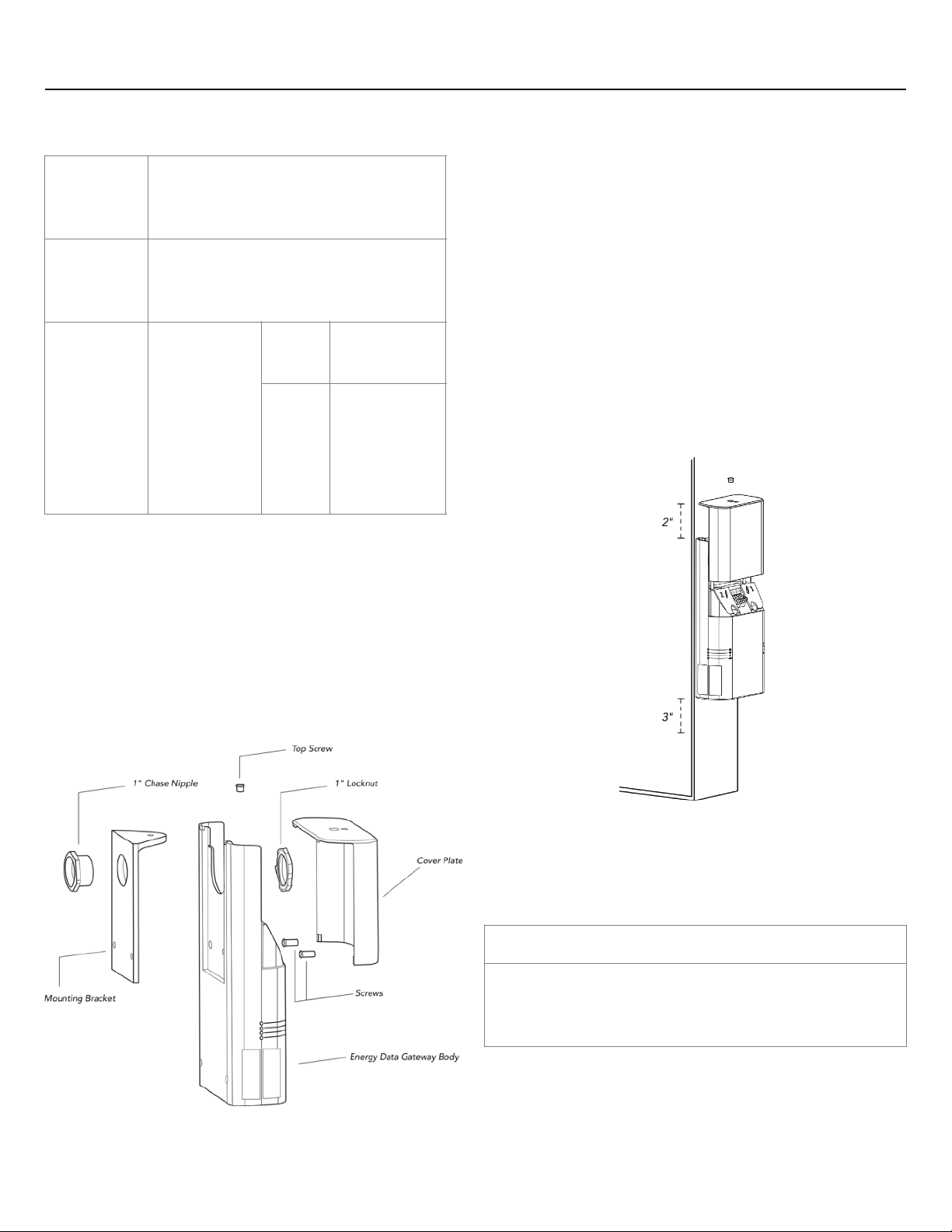
Energy Data Gateway parts are defined in Fig 1. Select a
mounting location (side, top, or bottom of panel) for the
unit. Make sure mounting location leaves 3” clearance
above top cap for sliding Cover Plate and Top Screw. And
leave 2” clearance on bottom for Ethernet port and Power
Plug. Fig 2
Side of panel (for surface-mount panels)
1. Look for an existing 1” knockout in the panel or create
a new 1” knockout, using the knockout punch or a
power drill with a hole cutter.
2. Detach front cap from Energy Data Gateway body by
removing top screw.
3. Mounting bracket is supposed to be attached on
Energy Data Gateway body, place Energy Data
Gateway body over panel knockout and insert 1”
chase nipple into the knockout hole. This will protect
cables from sharp edges. Fasten locknut onto nipple,
securing Energy Data Gateway body onto the panel.
SinglePhase Panel
Phases B typically marked by black
or red colored wire and Neutral
typically white colored wire.
Split-Phase
Panel
Phases A and B, typically marked by
2 different colored wires going to the
breakers.
Three-Phase
Phases A, B,
and C,
typically
marked by 3
different
colored wires
going into
the breakers.
Wye
Panels with 4
wires.
Delta*
Panels with 3
wires (no
neutral wire).
Fig 1
CONTACT US
If you are not sure where to install, call our support line at
1-844-837-3447 or email [email protected].
7
Fig 2
Page 8

IMPORTANT
For all installations: You should not insert the voltage tap cable leads in tandem with an
existing branch circuit wire (“double lugging”), unless the breaker is identified for the
termination of two conductors per NEC 110-14(a).
Select Breakers For Voltage Tap
Install one voltage tap on each phase of the panel. The voltage tap can be performed
without shutting off any breakers if there is at least 1 spare breaker per phase. If no spare
breakers are present, but there are empty slots in the panel, spare breakers can be
inserted and used for the voltage tap as well.
NOTE: If you do not have one spare breaker on each voltage phase, you will need to briefly shut down the voltage
tap breakers to complete this step. Please confirm with building operators that this will not interfere with
operations or safety protocols.
1. Open panel and locate 1 spare breaker on each phase. Choose breakers as close to
each other as possible to keep the wires organized.
NOTE: If the panel does not have any spare breakers, shut off 1 breaker on each phase.
2. Label selected breakers ‘Switch for VS sub-metering’.
NOTE: Energy Data Gateway voltage taps have a built-in in-line fuse; does not require additional fuse protection.
8
Page 9
Install Voltage Tap
9
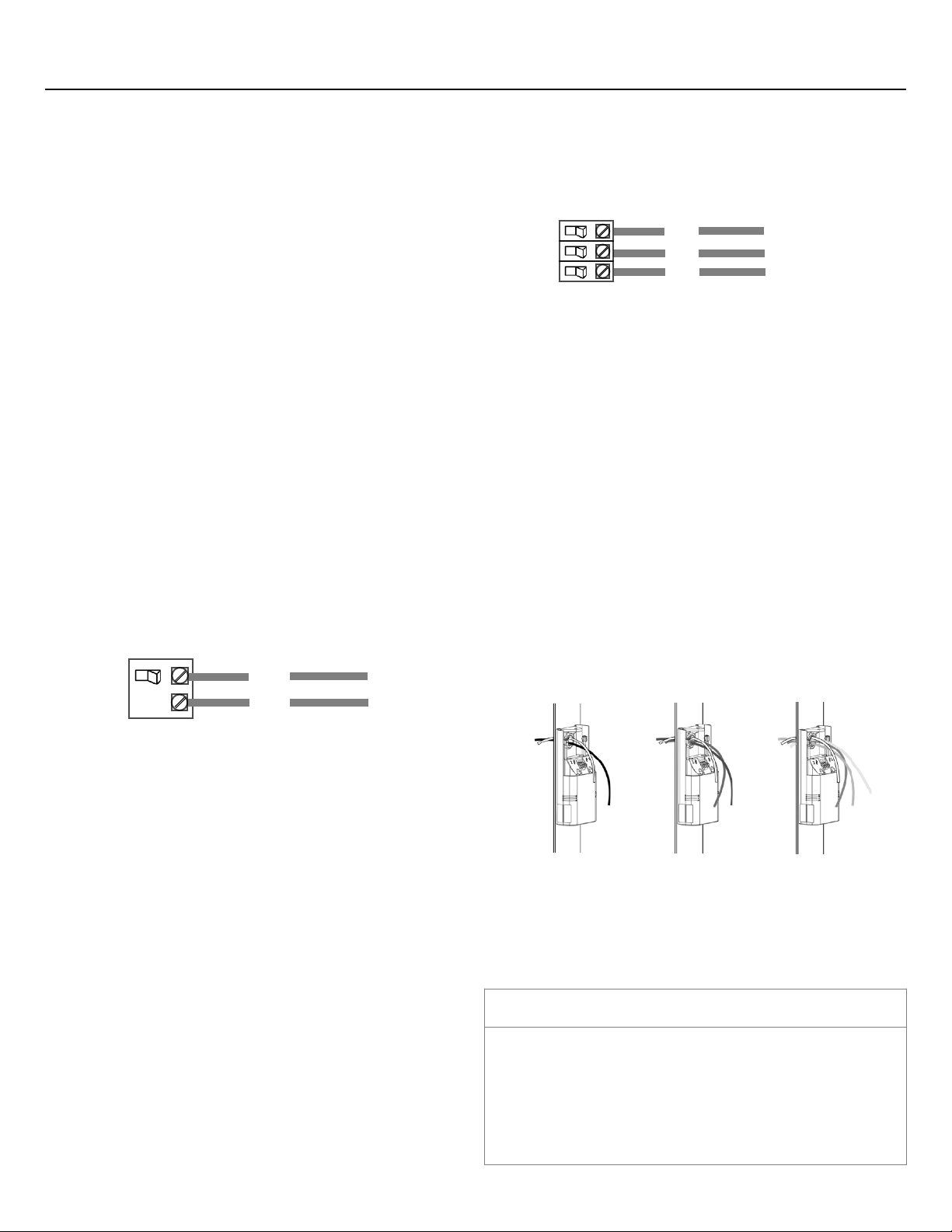
For Single-phase Panel
Voltage tap using spare breakers:
1. Ensure the breakers are turned off. Connect 1 voltage
tap cable to breaker.
2. Wire the neutral. Attach the white voltage tap cable to
the neutral bar.
3. Route wires through knockout and into the mounting
bracket. Fig 3.
Voltage tap using wall receptacle:
1. If there are no spare breakers, you can power the system
from a wall receptacle. Strip the cable, to identify neutral
and power, you do not need ground. Please confirm
with building operators and follow local jurisdiction.
2. Wire the neutral. Attach the white voltage tap cable to
the neutral bar.
3. Route wires through knockout and into the mounting
bracket. Fig 3.
For Split-Phase Panel
Voltage tap using spare breakers (Fig 6):
1. Ensure the breakers are turned off. Connect 2 voltage
tap cables to breakers.
2. Wire the neutral. Attach the white voltage tap cable to
the neutral bar.
3. Route wires through knockout and into mounting
bracket. Fig 4.
Voltage tap using wired breakers:
1. If you do not have one spare breaker on each voltage
phase, you will need to briefly shut down the voltage
tap breakers to complete this step. Please confirm with
building operators that this will not interfere with
operations or safety protocols. Please follow local
jurisdiction requirements for tap installs.
2. Wire the neutral. Attach the white voltage tap cable to
the neutral bar.
3. Route wires through knockout and into mounting
bracket. Fig 4.
For Three-Phase Panel
Voltage tap using spare breaker:
1. Ensure the breakers are turned off. Connect 3 voltage
tap cables to breakers. Fig 7.
2. Wire The Neutral (for wye configuration).
3. Route Wires. Route wires through knockout and into the
mounting bracket. Fig 5.
4. Splice Phase A (for delta configuration). Use splicing
connector on Phase A.
Voltage tap using wired breakers:
1. If you do not have one spare breaker on each voltage
phase, you will need to briefly shut down the voltage
tap breakers to complete this step. Please confirm with
building operators that this will not interfere with
operations or safety protocols. Please follow local
jurisdiction requirements for tap installs.
2. Wire The Neutral. Attach the white voltage tap cable to
the neutral bar.
3. Route Wires. Route wires through knockout and into the
mounting bracket. Fig 5.
Wire The Neutral
If the panel has a neutral bar (is a wye configuration panel),
attach the white voltage tap cable to the neutral bar.
Fig 6
≈
A
B
C
Fig 7
Fig 3
Fig 4
Fig 5
A
B
≈
IMPORTANT
Warranty will be breached and considered void in
connection to loss or damaged equipment due to
improper wiring.
See Connect Voltage Cables to Energy Gateway for
connecting Voltage Tap on next page.
Page 10
Connect Voltage Cables to Energy Data Gateway
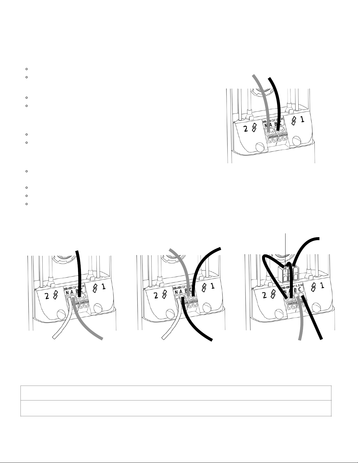
• Single Phase Panel. Fig 8.
Connect Neutral to ‘N’ terminal.
Connect remaining 1 wire into ‘B’ terminal.
• Split Phase Panel. Fig 9.
Connect Neutral to ‘N’ terminal.
Connect remaining 2 wires into ‘A’, ‘B’ terminals. Be sure
to match each wire to the correct phase.
• Three-Phase Wye Panel. Fig 10.
Connect Neutral to ‘N’ terminal.
Connect remaining 3 wires into ‘A’, ‘B’, ‘C’ terminals.Be
sure to match each wire to the correct phase.
• Three-Phase Delta Panel. Fig 11.
Use splicing connector on Phase A. There will be 2,
Phase A wires.
Connect one Phase A wire to the “N” terminal.
Connect second Phase A wire to the “A” terminal.
Connect remaining 2 wires to ‘B’ and ‘C’ terminals. Be
sure to match each wire to the correct phase.
IMPORTANT
DO NOT connect phase B to the ‘N’ terminal as this will result is short circuiting the energy data gateway
Fig 8
Black
Neutral
Fig 9
Black
Neutral
Red
Fig 10
Blue
Red
Neutral
Black
Red
Blue
Black
Splicing Connector
Fig 11
Neutral
10
Page 11
Install and Connect CTs
Select Appropriate CTs
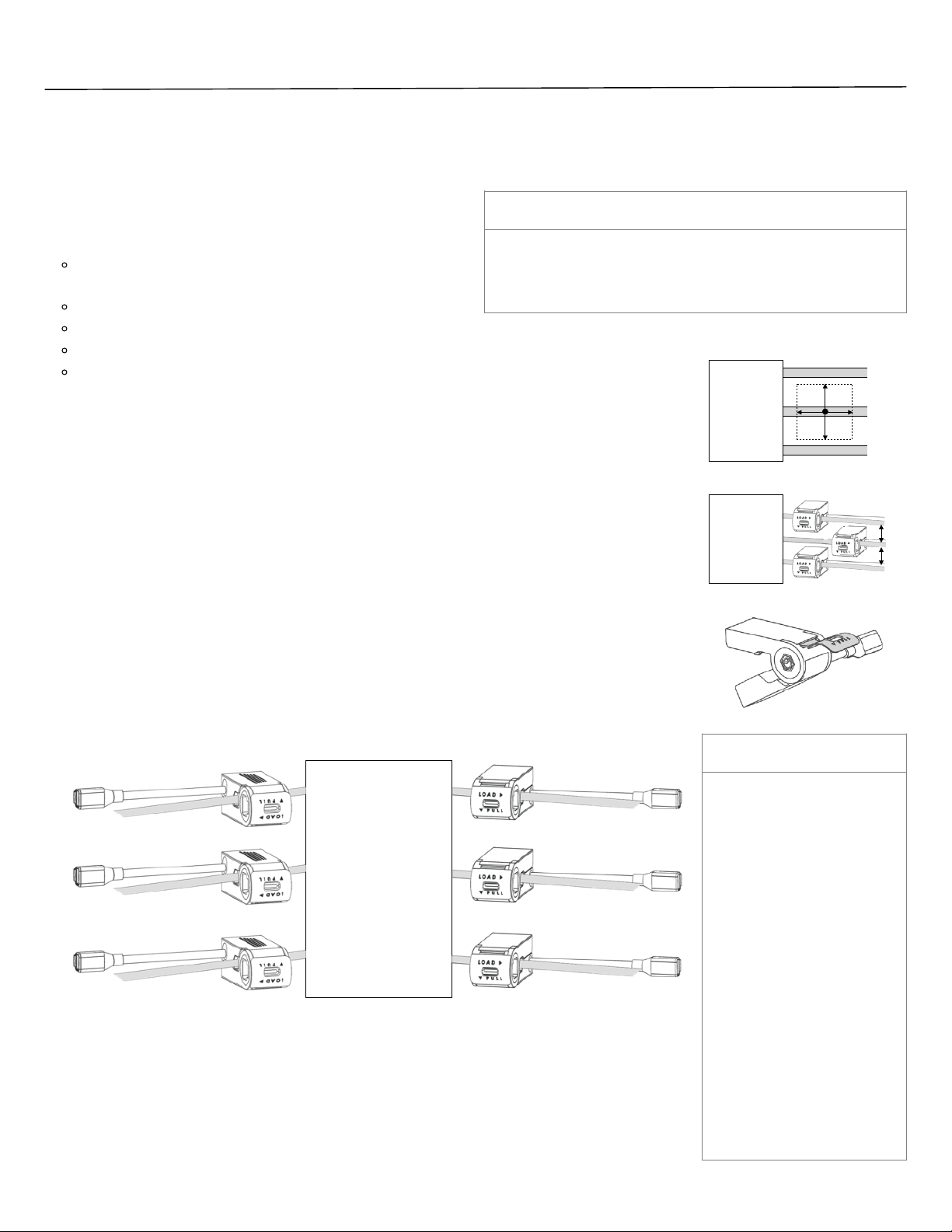
NOTE: Select the appropriate CTs for breaker ampacity. Larger amperage circuits may require the use of Large CTs
in combination with high current CT interface modules.
Verdigris offers the following CT sizes
(up to 21 per chain; 42 total per system):
• Verdigris Smart CT
60A
• Large CTs
200 A Hinged CT
4” 500 A Coil CT
7” 500 A Coil CT
Larger sizes available by custom order
Verify CT Install Location
Make sure there is a vertical and horizontal clearance of 1” around each cable at the point
of desired CT installation as shown in Fig 12. If clearance between adjacent cables is
0.5"-1.0", stagger CT installation as shown in Fig 13. If a 0.5" clearance does not exist, this
product may not be suitable for your installation. Please contact your local building
inspector for final determination.
Install CTs
1. Open the CT loop by pulling plastic tab up and out towards ‘PULL’ arrow direction.
Fig 14.
2. Starting from the top of the panel, position CT window around circuit breaker wire
making sure CT cable is facing away from the breaker.
3. Close CT loop by snapping CT ends together. It may be easier to close CT by pulling
plastic tab with one hand while applying pressure on CT top & bottom surfaces with the
other hand. Fig 15.
IMPORTANT
The ‘LOAD’ arrow should
point in the direction of
current flow (i.e. left
breaker CT ‘LOAD’ arrow
should point to the left,
and vice versa for the right
breaker CTs).
Make sure individual CTs
are attached to desired
circuit wires before daisy
chaining CTs together
(see Connect Multiple CTs
section on p.11).
CTs must be securely
closed for accurate data
collection.
4. Repeat steps 1-3 with more CTs until all desired circuit wires have a CT attached.
Spare breakers with no wires installed can be skipped.
NOTE: A maximum of 21 CTs may be installed in continuity. This means up to 21 CTs (or up to 7 high current
CT interface modules) may be mounted on either side of a panel, which covers a standard 42 circuit panel.
CONTACT US
If you are not sure which CTs are right for your breaker,
call our support line at 1-844-837-3447 or email
[email protected].
Fig 15
Circuit
Breakers
Fig 12
Circuit
Breakers
1“
Fig 14
Fig 13
0.5“-1“
Circuit
Breakers
0.5“-1“
11
Page 12
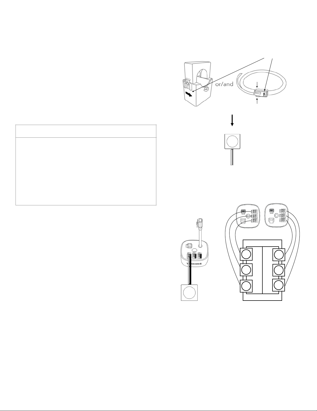
Fig 17
Large CTs & Verdigris High Current CT Interface Module
Large CTs can be installed around a conductor. There are
two types of CTs: hinged CTs and coil CTs. Fig 16.
1. Open the large CT:
• Hinged CTs: Unlatch the CT at the opposite end of the
hinge by lightly pulling up and lifting the latch.
• Coils: Squeeze the ends to release the latch and open
the coil.
2. Wrap the opening of the CT around the large circuit wire.
3. Securely close the CT.
• Hinged CTs: Click the latch closed. Double check for the
correct CT orientation via the load arrow or CT label.
• Coils: Squeeze the ends to release the latch and insert
end of the coil. Double check for correct CT
orientation via the load arrow.
4. Insert the 2 wire leads from the large CT into the
Verdigris high current CT interface module terminal
block. Match the colors of the wire leads with the black
and white ports in the high current CT interface module
(black on the right, white wire on the left). Fig 17.
5. Orient the high current CT interface module terminal
blocks on each side of the panel as shown in Fig 18.
6. Attach large CTs to the high current CT interface
module in order of 1, 2, 3 as shown in Fig 18.
7. Using the magnet on the bottom of the high current CT
interface module, mount it to any grounded metal
surface in the panel, such as the side or back walls.
NOTE: CT chains and large CTs/high current CT interface modules can be
used interchangeably in terms of order. For example, on the left side of a
panel, the installation could begin with 15 CTs, followed by 3 large CTs with
a high current CT interface module, followed by another 3 CTs.
IMPORTANT
Large CTs must be oriented properly, otherwise inaccurate
data may result. Large CTs should be mounted such that
the load arrow points in the direction of the load on the
circuit. In most cases, the arrow points away from the
breaker.
For hinged CTs, if it is difficult to see the load arrow, the CT
label should be mounted with the label towards the
source.
Hinged CT
Coil CT
squeeze
Fig 16
In this installation manual, we will use
this symbol to represent large CTs.
Load arrow
Fig 18
12312
3
12
Page 13
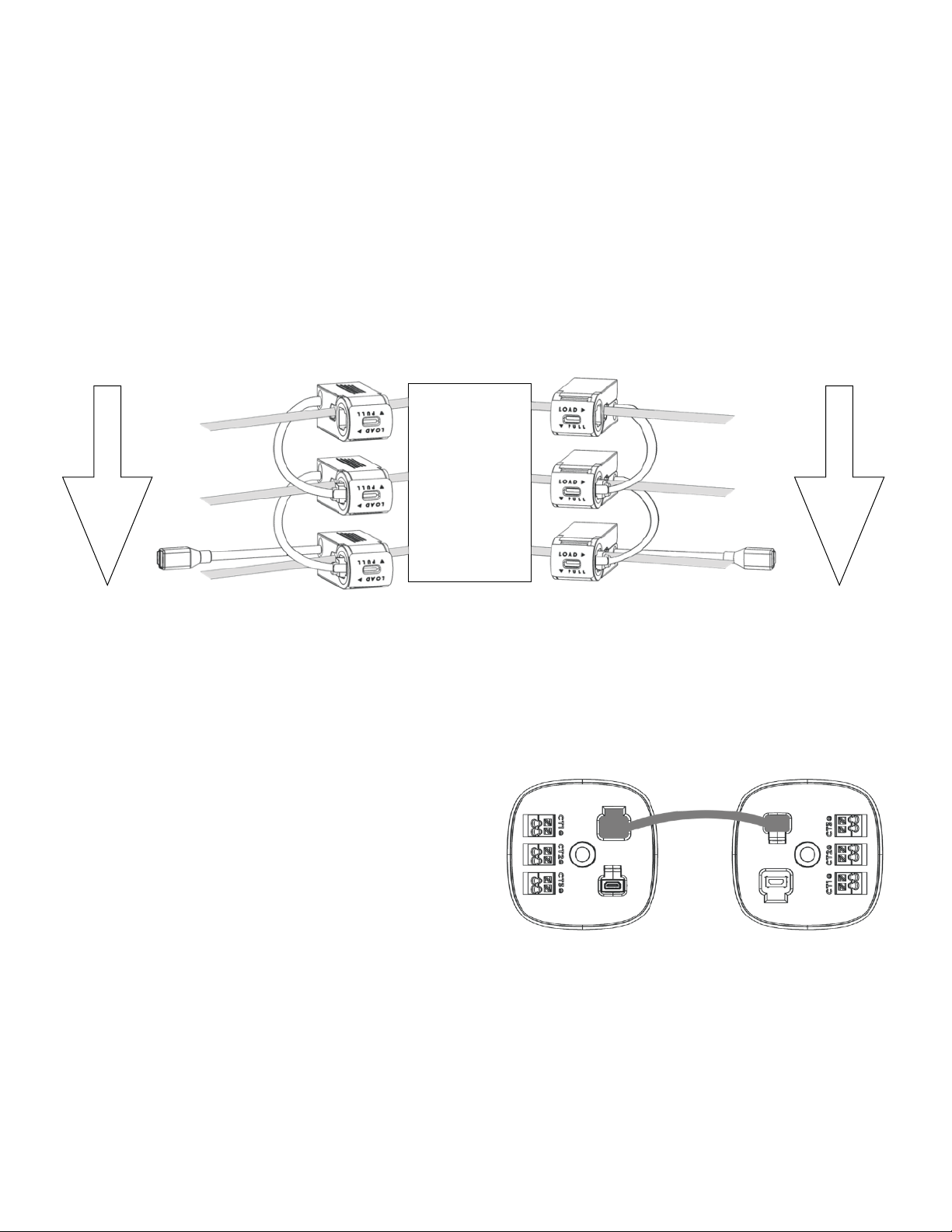
Fig 20
Connect Multiple CTs
Daisy chain CTs together. Fig 19.
1. Starting at the top left breaker, insert CT cable latch into the female cable connector on
the CT directly below.
2. Repeat until all CTs have been connected on the selected breakers. There should be an
unattached female cable connector on top CT and an unattached CT cable on the
bottom CT.
3. Repeat steps 1 & 2 for the right breakers, starting at the top CT.
Fig 19
Connect Multiple Verdigris High current CT interface modules
If your panel installation requires multiple high current CT
interface modules:
Connect the cable pigtail from the high current CT interface
modules to the input port of the next high current CT
interface module. A CT extension cable may be used if the
high current CT interface modules are positioned such that
the pigtails do not reach. Fig 20.
Circuit
Breakers
Direction
of daisy
chain
Direction
of daisy
chain
13
Page 14
Connect CTs
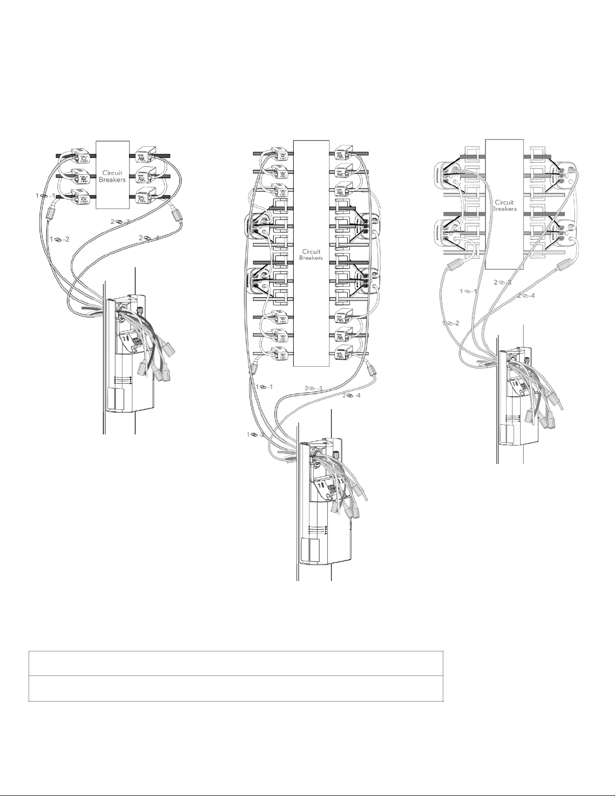
Connect CT chain using extension cables and route wires through knockout into mounting
bracket. Fig 21.
Fig 21
IMPORTANT
The maximum cable length for an entire chain loop is 8m or approximately 26ft.
(a)
(b)
(c)
14
Page 15
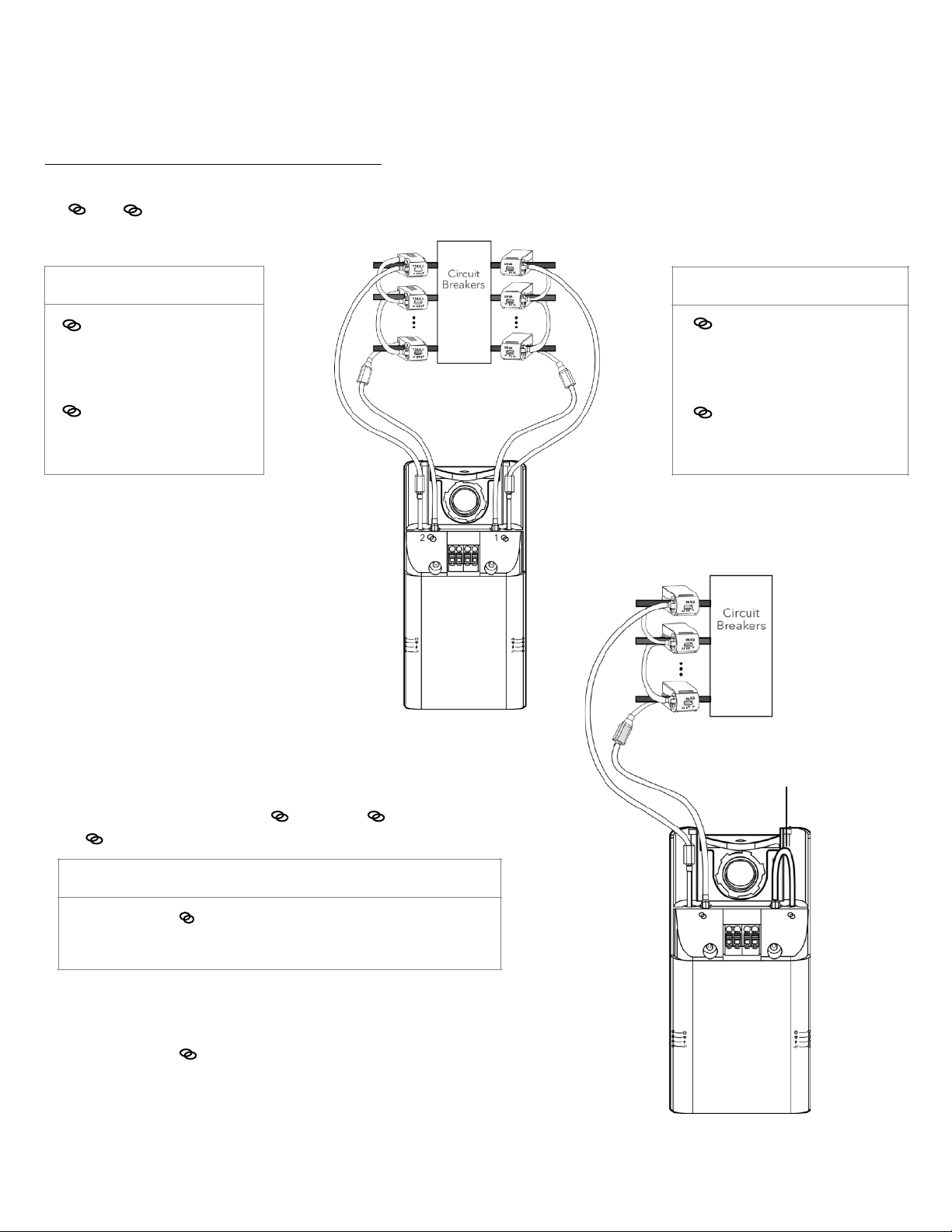
Connect CTs to the Energy Data Gateway
FOR INSTALLATIONS USING ONLY CT CHAINS:
Using the CT extension cables to connect left & right CT chains to the corresponding
1 & 2 female and male connectors on the Energy Data Gateway, as shown below.
Fig 22.
Fig 22
IMPORTANT
1 Male connector must
connect to the
TOP LEFT CT
1 Female connector must
connect to the
BOTTOM LEFT CT
IMPORTANT
2 Male connector must
connect to the
TOP RIGHT CT
2 Female connector must
connect to the
BOTTOM RIGHT CT
Fig 23
For installations with CTs on only 1 chain
When there are not CT(s) for 1 , connect 1 male connector
to 1 female connector.
Use two CT extension cables to connect CT chain ends to the
corresponding 2 female and male connectors on the
Energy Data Gateway. Fig 23.
IMPORTANT
Use chain two (2 ) if you are only use one chain.
Close the other chain loop when there is only one sensor chain.
2
2
N A BC
N A BC
Make sure the chain is closed.
15
Page 16
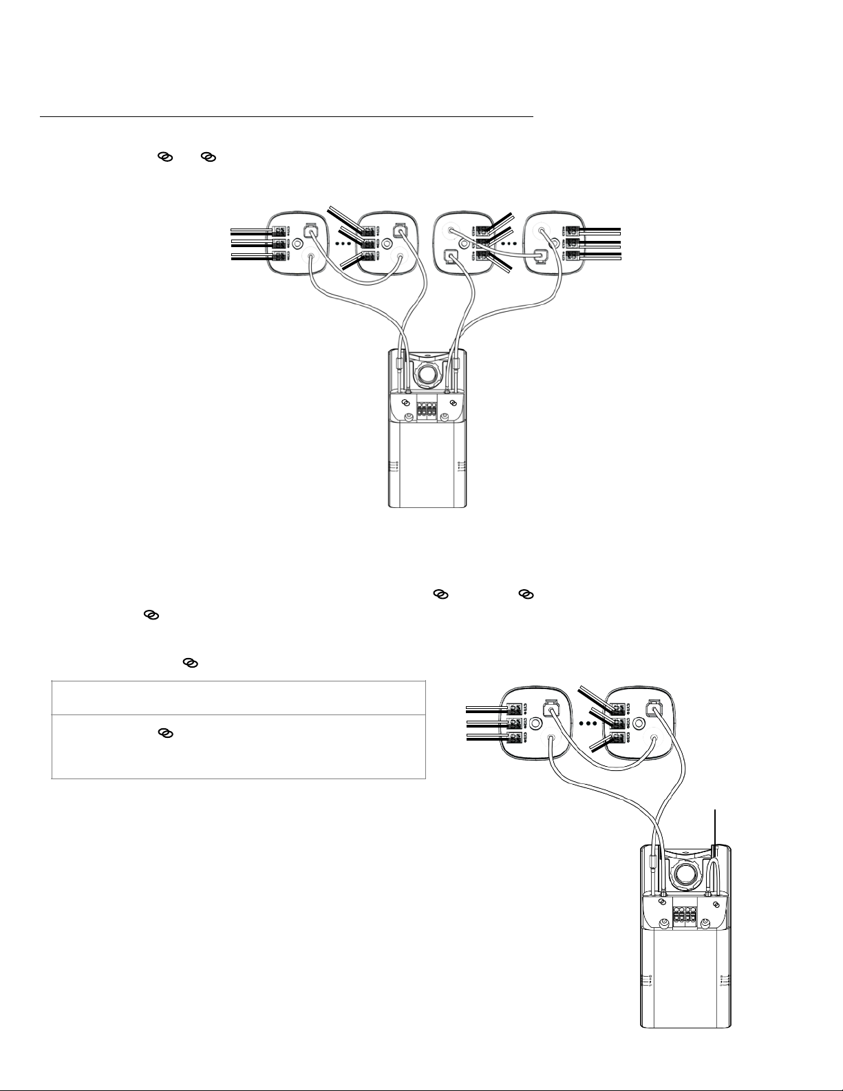
FOR INSTALLATIONS USING ONLY HIGH CURRENT CT INTERFACE MODULES:
Use CT extension cables, connect high current CT interface module chains to the
corresponding 1 & 2 male & female connectors on the Energy Data Gateway as shown
below. Fig 24.
Fig 24
For installations with High Current CT Interface Module(s) on only 1 chain
When there are not high current CT interface module(s) for 1 , connect 1 male
connector to 1 female connector.
Use two CT extension cables to connect high current CT interface modules chain ends to
the corresponding 2 female and male connectors on the Energy Data Gateway. Fig 25.
IMPORTANT
Use chain two (2 ) if you are only use one chain.
Close the other chain loop when there is only one sensor chain.
Fig 25
2
N A BC
1
2
N A BC
Make sure the
chain is closed.
16
Page 17
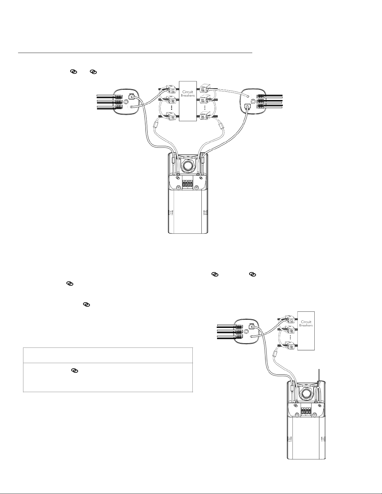
Fig 26
FOR INSTALLATIONS USING CTS AND HIGH CURRENT CT INTERFACE MODULES:
Using CT extension cables, connect high current CT interface module/CT chains to the
corresponding 1 & 2 female and male connectors on the Energy Data Gateway, as
shown below. Fig 26.
For installations with High Current CT Interface Module/CT(s) on only 1 chain
When there are not High Current CT Interface Modules/CT(s) for 1 , connect 1 male
connector to 1 female connector.
Use two CT extension cables to connect High Current CT Interface Modules/CT chain ends to
the corresponding 2 female and male connectors on the Energy Data Gateway.
Fig 27.
Fig 27
IMPORTANT
Use chain two (2 ) if you are only use one chain.
Close the other chain loop when there is only one sensor chain.
2
2
N A BC
N A BC
Make sure the
chain is closed.
17
Page 18
Check the CTs
• Check each CT to ensure that they are closed properly.
• Check the load arrow on the CTs points in the direction of
the load.
• Check all High Current CT Interface Modules to ensure
Large CT leads are properly inserted into the terminal
blocks, and all large CTs are snapped closed.
• Check all data cable connections to ensure they are
properly seated.
Chain Check
The following procedure tests whether digital sensor data
can flow to the Verdigris Energy Data Gateway by checking
whether the connections are seated properly and the
physical integrity of the CT and high current CT interface
module chain. It is recommended to follow this procedure
1) after a Verdigris system has been installed, and 2) while
the panel remains open to access the CTs and high current
CT interface modules. Failure to verify the physical integrity
of the sensor chain through Chain Check may result in
inability to gather any data from the system.
1. Power on the gateway using one of the three options
below to provide power:
a. Panel Breaker: Switch on breakers that are powering
the Energy Data Gateway. If the panel is deenergized for installation then follow option b or c
below.
b. Plug Receptacle with Available Power: Use a power
cord with a 5V AC connector with a 5.5mm barrel
jack. Plug power cord into a wall receptacle, battery,
or battery powered work lights that have an available
plug. Plug the barrel jack into the bottom of the
Energy Data Gateway (Fig 29).
c. USB plug to Available Power: Use a USB plug to an
external battery such as a cell phone battery.
2. Turn on Energy Data Gateway using the rocker switch at
the bottom of the unit When the gateway is energized,
the light next to the switch will be green. Wait for 2
minutes. Indicator lights on the side of the gateway will
turn on.
Battery Specification:
I. Portable and capable of being moved around easily.
II. Battery: battery pack or emergency power source for
accessories.
3. CT Chain Check runs automatically when the system is
first powered on and when the Setup button is pressed
once. The CTs and high current CT interface modules
have LED lights which will display a diagnostic lighting
sequence. The CT chain indicator light will change from
blinking blue to red or green during chain check. Please
check the Error Code table on page 21 for guidance. The
LED indicator light on the Energy Data Gateway will
display blinking red if the break is on chain 1 and solid
red for a break in chain 2.
4. A broken, unplugged, or poorly seated CT or high
current CT interface modules cable will cause a
difference in the flashing light patterns on the broken
sensor chain. The point at which the light pattern differs
indicates the area of the chain break. Fig 28 shows an
example of these differing light patterns. The possible
light patterns displayed by the CT/ high current CT
interface modules are: On, Off, or Blinking.
a. Reseat the cables in the chain for the 2 CTs or high
current CT interface modules where the LED light
pattern changes. Do not increase force or pressure
when reseating the cables, instead re-insert at
slightly upward angle and listen for a click.
System Chain Check
IMPORTANT
Double-check the installed CTs, as the physical
movement of items inside of the panel from CT
installation and data cable connection can cause CTs to
become loose.
18
IMPORTANT
Please note that Verdigris will not assume liability for
damage or injury incurred from the use of portable
battery and inverter packs.
Page 19
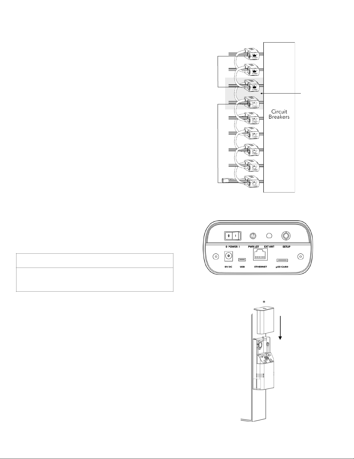
5. Click the “Setup” button once to repeat the CT lighting
sequence for Chain Check as needed. Fig 29.
6. Chain check is complete when the LED indicator light on
the Energy Data Gateway for the CT chain is solid green.
Powering Energy Data Gateway
Once chain check has been performed and validated,
unplug the alternate power source. Once the voltage tap
cables have been connected to the terminal blocks, turn
breakers used for voltage tap on. Turn on the Energy Data
Gateway using the rocker switch at the bottom. A green
light next to the switch will indicate that the unit is receiving
power. An indicator light at the side of the unit will be
green if the system is working correctly.
Clean Up and Close the Panel
• Excessive cable lengths can be coiled to save space, and
to keep the interior of the panel neat and tidy.
• Excessively long wires from voltage tap cables can be cut.
• Close the cover plate (Fig 30) and proceed to commission
Energy Data Gateway.
19
Fig 28
Light
Pattern 1
Light
Pattern 2
Reset the cables
associated with
these two CTs
or high current
CT interface
modules.
Fig 29
Fig 30
IMPORTANT
Click the “Setup” button once to repeat the CT lighting
sequence for Chain Check as needed.
Page 20
Setup & Commission Energy Data Gateway
Commissioning
Once installation is complete, power on the system safely. Begin setting up the system with
our setup application. This final process associates the Energy Data Gateway to a panel
and the circuits to equipment. Setup ensures the metered data is transmitted to the cloud.
1. The Energy Data Gateway is emitting a local wireless hotspot. Connect to the hotspot via
smartphone, tablet or laptop. Look for a wifi network called “Verdigris- BBEXXXXXXXX”,
with the serial number of the specific Energy Data Gateway. It may be necessary to
disconnect the regular mobile data network on your mobile device which can also be
achieved by switching to airplane mode, and even enabling wifi.
2. Open any web browser and navigate to connect.verdigris.co (URL address: 192.168.8.1).
The system should automatically connect to the setup screen.
3. Select a network connectivity option of Wifi, 4G LTE, or Ethernet.
• Wifi: Be prepared to identify the network name and enter the password.
• 4G LTE: The system should connect automatically. For a reliable connection, the
signal should be greater than -58 dBm (e.g. -32 dBm). A value of -96 dBm indicates
no signal.
• Ethernet: The system should connect automatically using DHCP IP. If a static IP is
required, contact [email protected].
• Troubleshooting: If not able to complete in the setup application, please take a series
of detailed, high-resolution images or video of in side the panel and installation. Be
sure breakers and CTs are visible in the photo taken. Email images to
[email protected], with the Energy Data Gateway serial number as the email
subject line. The serial number is located on the service panel near the indicator lights.
4. Select Check Connected Sensors on the Menu- Check the number of CTs connected on
each chain with Scoping sheet. Make notes to associate the breakers on the Scoping
Sheet so that it equals the number of installed CTs per chain. Mismatches will result in
inaccurate data.
5. Follow the onscreen instructions to complete the commissioning process. This process
will associate each CT to an electrical circuit, and is necessary to retrieve Verdigris data
from the system.
Congratulations!
Your Verdigris system is now installed and set-up, contact us for user access and login
information.
20
IMPORTANT
Double click Setup button to re-surface the hotspot and setup menu.
Page 21
Error Codes
If you need direct assistance, call our support line at 1-844-837-3447 or
email [email protected]
The top indicator light serves as a guide to overall system
health. If the light starts blinking red, there is a problem
with one or more devices within the system. The solid white
means everything is good.
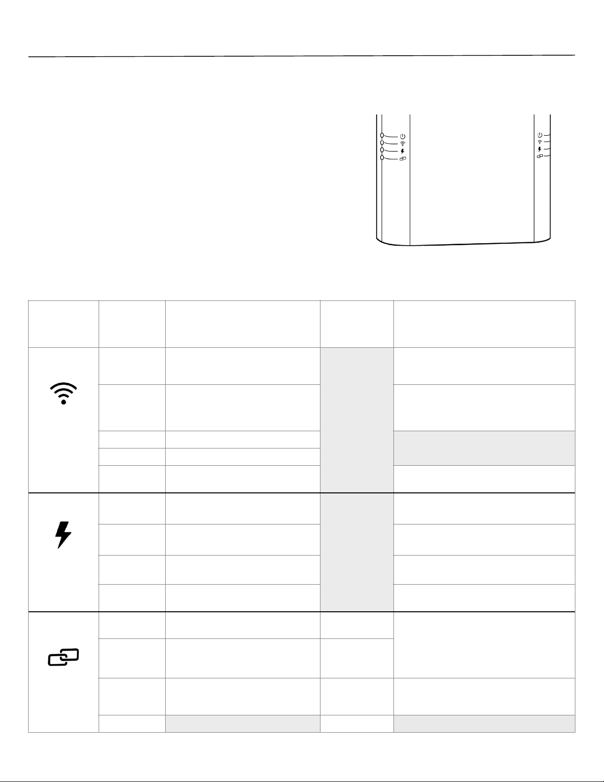
To troubleshoot system: Identify indicator lights on the
sides of the panel pictured on the right. Fig 31, refer to the
table below.
Wait for at least 1 minute for the system to cycle through
diagnostics. If the indicator lights are blinking white for
greater than 2 minutes, please contact support.
To reboot the system: Hold the system Setup button for
approximately 8 seconds.
Fig 31
Service Panel
Operation Mode
Energy Data
Gateway
LED Indicator
Interpretation
CT or high
current CT
interface module
Indicator
Troubleshoot
Wireless
(LTE, Ethernet
and/or WiFi)
Blinking Red
Cannot connect to Internet, system WiFi
hotspot is broadcasting
Error with connectivity, please connect to the
system via your mobile device to debug wireless
connectivity. (See page 20)
Red
Cannot connect to Internet, no system
hotspot is broadcasting
Not connect to building LAN
Error with connectivity, please press the reset
button for 1second to bring up setup-tools and
debug wireless connectivity. (See page 20)
Blinking White
Busy system
Blinking Green
Connected, system hotspot broadcasting
Green
Connected, no system hotspot
broadcasting
To broadcast hotspot press the reset button for
one second.
Voltage
Red
Two voltage phases and Neutral
attached
Confirm panel is a three-phase delta 240V, splitphase, or two-phase 120V configuration.
Blinking White
Busy system
System is processing. CT chain indicator must be
green first for LED indicator to change.
Blinking Green
Single voltage phase and Neutral
attached
Panel is connected as a single phase
configuration.
Green
Three voltage phase and Neutral
attached
Panel is connection as a three-phase wye
configuration.
CT Chain
Blinking Red
Break in CT chain 1
Chain 1 lights are
on until break.
CT chain is not completely connected. Check for
a break in the CT chain based on a difference in
CT LED lights (on or off). Reseat the cables in the
chain for the 2 CTs where the CT LED light
pattern changes. System will cycle to check CT
chain integrity every 10 seconds.
Red
Break in CT chain 2
Chain 2 lights are
on until break.
Blinking White
System is performing chain check.
Blink White
Wait for LED indicator to change. System will
cycle to check CT chain integrity every 10
seconds.
Green
Off
21
Page 22

Future Panel Modifications
In the event of panel modifications or changes to the circuits you are monitoring, your
Energy Data Gateway may need to be recommissioned. Please repeat steps to
Commission your Energy Data Gateway and contact Verdigris for additional support at
[email protected].
Moving an installed and setup Energy Data Gateway to an alternate panel is not
recommended nor supported and will void warranty.
22
Page 23

23
Page 24

NASA Ames Research Park Building 19, #1077
Moffett Field, CA 94035
 Loading...