

Page 1
Hose pumps
Safety; operation and
maintenance manual
(VF5 - VF80 Product Range)
Version 5: August 2007
Page 2

Table of Contents
Disclaimer of Warranty and Limitations of Liability......................................................................... 6
1. Introduction ............................................................................................................................. 7
2. Safety Issues........................................................................................................................... 8
2.1 Safety Alert Symbol...................................................................................................... 8
2.2 Signal Words................................................................................................................ 8
2.3 Safety First ................................................................................................................... 9
2.4 Pump Safety Features.................................................................................................. 9
2.5 Operational Safety...................................................................................................... 10
2.6 Maintenance Safety.................................................................................................... 11
2.7 Assembly, Installation and Commissioning................................................................ 12
3. Theory of the Pump............................................................................................................... 13
3.1 Working Principles...................................................................................................... 13
3.2 Features of a Hose Pump .......................................................................................... 13
3.3 Advantages of VERDERFLEX ................................................................................... 13
3.4 Product Range ........................................................................................................... 14
3.5 Pump Construction..................................................................................................... 14
3.6 Limitations of the Pump.............................................................................................. 17
3.7 Pump Selection .......................................................................................................... 18
3.8 VERDERFLEX Hose .................................................................................................. 18
4. Safety, Operation and Maintenance Instructions .................................................................. 19
4.1 General – tools and facilities ...................................................................................... 19
Pump sizes & weights........................................................................................................... 19
4.2 Assembly.................................................................................................................... 19
4.3 Installation .................................................................................................................. 30
4.4 Commissioning........................................................................................................... 31
4.5 Operation.................................................................................................................... 32
4.6 Maintenance............................................................................................................... 33
4.7 Drive Selection ........................................................................................................... 44
4.8 Lubrication.................................................................................................................. 45
4.9 Fault Finding............................................................................................................... 46
5. Accessories and Options ...................................................................................................... 48
5.1 Accessories and Options............................................................................................ 49
6.1 Normal Operation Risk & Preventative Measures:..................................................... 52
6.2 Explosive Operation Risk & Preventative Measures: ................................................. 53
6.3 Explosion Proof Labelling:.......................................................................................... 57
6.4 Pump & Hose: Storage during Plant shutdowns / on site storage.............................. 57
6.5 Other Information: ...................................................................................................... 59
Warranty Registration ...........................................................................................................59
Appendix A................................................................................................................................... 61
VERDERLUBE Safety Data Sheet........................................................................................ 61
1 Identification of the Substance/Preparation and of the Company/Undertaking..................... 61
1.1 Identification of Substance or Preparation ................................................................. 61
1.2 Company Identification............................................................................................... 61
2 Composition / Information on Ingredients ............................................................................. 61
3 Hazards Identification............................................................................................................ 61
4 First Aid Measures ................................................................................................................ 62
4.1 Ingestion..................................................................................................................... 62
4.2 Inhalation.................................................................................................................... 62
4.3 Skin Contact............................................................................................................... 62
4.4 Eye Contact................................................................................................................. 62
5 Fire Fighting Measures .........................................................................................................62
5.1 Extinguishing Media ................................................................................................... 62
2
Page 3

5.2
Extinguishing Media To Avoid.................................................................................... 62
5.3 Unusual Fire and Explosion Hazards......................................................................... 62
5.4 Special Protective Equipment for Fire fighters ........................................................... 63
6 Accidental Release Measures............................................................................................... 63
6.1 Personal Protection.................................................................................................... 63
6.2 Environmental Precautions ........................................................................................ 63
6.3 Methods for Cleaning Up............................................................................................ 63
7 Handling and Storage ...........................................................................................................63
7.1 Handling ..................................................................................................................... 63
7.2 Storage....................................................................................................................... 63
8 Exposure Controls / Personal Protection .............................................................................. 63
8.1 Personal Protection.................................................................................................... 63
8.2 Occupational Exposure Limits.................................................................................... 64
9 Physical and Chemical Properties ........................................................................................ 64
10 Stability and Reactivity ...................................................................................................... 64
10.1 Conditions to Avoid................................................................................................. 64
10.2 Materials to Avoid ................................................................................................... 64
10.3 Hazardous Decomposition Products ...................................................................... 64
11 Toxicological Information................................................................................................... 64
11.1 Toxicity Data........................................................................................................... 64
11.2 Significant Data with Possible Relevance to Human Health................................... 65
12 Ecological Information ....................................................................................................... 65
12.1 Mobility.................................................................................................................... 65
12.2 Persistence and Degradability ................................................................................ 65
12.3 Bio Accumulative Potential ..................................................................................... 65
12.4 Aquatic Toxicity....................................................................................................... 65
13 Disposal Considerations.................................................................................................... 65
13.1 Waste Disposal Method(s)...................................................................................... 65
14 Transport Information ........................................................................................................ 66
15 Regulatory Information ...................................................................................................... 66
16 Other Information...............................................................................................................66
Appendix B................................................................................................................................... 67
1. Identification of the Substance/Preparation and of the Company/Undertaking..................... 67
1.1 Identification of Substance or Preparation ................................................................. 67
1.2 Company Identification............................................................................................... 67
2. Composition / Information on Ingredients ............................................................................. 67
3. Hazards Identification............................................................................................................ 67
4. First Aid Measures ................................................................................................................ 68
4.1 Ingestion..................................................................................................................... 68
4.2 Inhalation.................................................................................................................... 68
4.3 Skin Contact............................................................................................................... 68
4.4 Eye Contact................................................................................................................. 68
5. Fire Fighting Measures .........................................................................................................68
5.1 Extinguishing Media ................................................................................................... 68
5.2 Extinguishing Media To Avoid.................................................................................... 68
5.3 Unusual Fire and Explosion Hazards......................................................................... 68
5.4 Special Protective Equipment for Fire fighters ........................................................... 68
6. Accidental Release Measures............................................................................................... 69
6.1 Personal Protection.................................................................................................... 69
6.2 Environmental Precautions ........................................................................................ 69
6.3 Methods for Cleaning Up............................................................................................ 69
7. Handling and Storage ...........................................................................................................69
7.1 Handling ..................................................................................................................... 69
7.2 Storage....................................................................................................................... 69
3
Page 4

8.
Exposure Controls / Personal Protection .............................................................................. 69
8.1 Personal Protection.................................................................................................... 69
8.2 Occupational Exposure Limits.................................................................................... 70
9. Physical and Chemical Properties ........................................................................................ 70
10. Stability and Reactivity ...................................................................................................... 70
10.1 Conditions to Avoid................................................................................................. 70
10.2 Materials to Avoid ................................................................................................... 70
10.3 Hazardous Decomposition Products ...................................................................... 70
11. Toxicological Information................................................................................................... 70
11.1 Toxicity Data........................................................................................................... 70
11.2 Significant Data with Possible Relevance to Human Health................................... 71
12. Ecological Information ....................................................................................................... 71
12.1 Mobility.................................................................................................................... 71
12.2 Persistence and Degradability ................................................................................ 71
12.3 Bio Accumulative Potential ..................................................................................... 71
12.4 Aquatic Toxicity....................................................................................................... 71
13. Disposal Considerations.................................................................................................... 71
13.1 Waste Disposal Method(s)...................................................................................... 71
14. Transport Information ........................................................................................................ 72
15. Regulatory Information ...................................................................................................... 72
16. Other Information...............................................................................................................72
Appendix C................................................................................................................................... 73
4
Page 5

Appendices
A VERDERLUBE Safety Data Sheet
B VERDERSIL Safety Data Sheet
C Lifting Safety Data Sheet
D Black Food Grade Hose
E VERDERFLEX Spares List
F Shimming Charts & Performance Curves
5
Page 6

Disclaimer of Warranty and Limitations of Liability
This pump is warranted against defects in workmanship and material under normal use (rental
use excluded) for two years from date of purchase. This is to the extent that VERDER will at its
option replace, repair or refund, in full, the purchase price of the instrument of any part thereof
manufactured by VERDER, which in our opinion is defective. Also provided the instrument has
been operated in strict accordance with this manual, and has not been subjected to tampering,
abuse or exposed to highly corrosive and/or unspecified explosive conditions.
This warranty does not cover the conditions arising as follows:
• Failure of VERDER manufactured parts or components including hose, due to normal wear /
damage or failure, that in VERDER’s judgement arises from misuse
• Failure to implement the necessary safety procedures for use in the European Community of
a pump within an explosive atmosphere as laid down in latest EC Atex directive from 1st July
2003
• Failure to disclose the (intended or unauthorized) use of a pump within a known explosive
atmosphere
VERDER MAKES NO WARRANTIES, EXPRESSED OR IMPLIED, INCLUDING, WITHOUT
LIMITATION, ANY WARRANTIES OF FITNESS OR MERCHANTABILITY, EXCEPT AS
EXPRESSLY SET FORTH ABOVE. VERDER SHALL NOT BE LIABLE FOR ANY INJURIES,
LOSSES OR DAMAGES INCLUDING, BUT NOT LIMITED TO ANY PERSONAL INJURIES,
ANTICIPATED OR LOST PROFITS, INCIDENTAL DAMAGES, CONSEQUENTIAL DAMAGES,
COSTS, TIME CHARGES, OR OTHER DAMAGES OR LOSSES, IN CONNECTION WITH THE
INSTRUMENT, ITS USE OR ANY REPLACEMENT PARTS THEREFORE
This warranty is voided if the customer fails to follow any and all instructions, warnings or
cautions in this VERDERFLEX Hose Pump Safety, Operation and Maintenance Manual.
VERDER has made every effort to illustrate and describe the product(s) in this manual. Such
illustrations and descriptions are, however, for the sole purpose of identification and do not
express or imply a warranty that the products are merchantable or fit for a particular purpose, or
that the products will necessarily conform to the illustration or descriptions
If a manufacturing defect is found, VERDER will replace or repair the instrument or replace any
defective part thereof without charge. However, VERDERS obligation hereunder does not
include the cost of transportation of the instrument to VERDER or its return to the customer;
these costs must be borne by the customer. VERDER assumes no responsibility for damage in
transit, any claims for such damage should be presented to the carrier by the purchaser. In
addition, instead of replacing or repairing the instrument as aforesaid, VERDER may, at its sole
option, take back the defective instrument and reimburse the customer for the purchase price in
full settlement of any and all potential claims related to the purchase or use of the VERDERFLEX
hose pump
6
Page 7

1. Introduction
The Verder Group of companies have offices located in Austria, Belgium, China, Czech Republic,
France, Germany, Hungary, Japan, Norway, Poland, Romania, Slovakia, South Africa, The
Netherlands, United States and the UK. A network of worldwide distributors support our products in
other countries of which a full list can be seen at www.verderflex.com. Group headquarters are in
Holland.
Verder’s in-house designers and application engineers have developed a new generation of
products, the range of Peristaltic hose pumps, which are designed by Verder’s own production team.
Full product training and documentation is available, and Verder takes no responsibility for
malfunction of the pump caused by failure to follow these operating procedures; if operators do not
read and understand this manual, they are not considered by Verder to be qualified to assemble,
install, operate or maintain this equipment. As any pump is no more or no less than one component
part of an overall process, it is essential for the successful completion of the total process for the
pump to be working to its fullest potential, and for the operator to be fully conversant with the
operating principles of our hose pump.
Verder strives to maintain quality standards based upon ISO 9000 standards.
It is Verder policy to supply its documentation in a number of languages and software options, and
your Verder distributor will be able to assists you with the options available.
Verder recognizes its responsibilities to its customers around the world, and will always seek to
meet or exceed their expectations. Customer comments and feedback are always warmly welcomed
and input to the development of procedures and products, is common. Should you have any issues
on which you wish to comment, please return your comments to your local Verder distributor who
will then forward them for action to Verder Ltd.
7
Page 8

2. Safety Issues
2.1 Safety Alert Symbol
The symbol shown above is used to identify topics of primary safety concern and call attention to
instructions concerning your personal safety. Watch for this symbol, it involves important safety
precautions, and means “ ATTENTION! BECOME ALERT! YOUR PERSONAL SAFETY IS
INVOLVED!”
Read the message that follows and be alert to the possibility of personal injury or death
2.2 Signal Words
Signal words designate a degree or level of hazard seriousness. They are used in this manual
in accordance with ANSI Z535.4-1991 and are defined as follows:
• Indicates an imminently hazardous situation, which, if not avoided, will result in death or
serious injury. This signal word is limited to the most extreme situations
• Indicates a potentially hazardous situation, which, if not avoided, could result in death or
serious injury.
• Indicates a potentially hazardous situation, which, if not avoided, may result in minor or
moderate injury. It may also be used to alert against unsafe practices. It may also be used
for property damage-only accidents.
8
Page 9

2.3 Safety First
• The information in this manual is essential for the safe operation and servicing of
VERDERFLEX pumps. This manual must be read and understood in particular all of section
6 for operation in normal and explosive atmospheres, before operating or servicing such
pumps
• The employer shall instruct each employee in the recognition and avoidance of unsafe
conditions and the regulations applicable to his work environment to control or eliminate any
hazards or other exposure likely to cause injury
• It is understood that safety rules within individual companies vary. If a conflict exists
between the material contained in this manual and the rules of a using company, the more
stringent rules should take precedence
• This manual should be kept available to operating and maintenance personnel. Additional
copies of this manual may be acquired free of charge from VERDER via your distributor
• Safety suggestions from users will be given the most serious consideration. This is
especially true of advice for minimising problems associated with safety misuse, which cannot
be identified in advance during the production of the pump unit. Comments and
recommendations should be submitted to VERDER via your distributor.
• Throughout this manual these safety instructions are repeated, together with other safety
notes and tips. The relevant information will act as a guideline for you in operating the pump;
alternative courses of action are also described should you be unable for any reason to follow
those procedures initially given for any procedure. You are advised to follow these
guidelines to achieve maximum efficiency
2.4 Pump Safety Features
The VERDERFLEX has a number of in-built features, which have been designed specifically to
ensure your safety during operation and maintenance of the unit:
• Disaster proof design – the casing will contain any spillage preventing leaks and
contamination of product
• Low and high level controls for automatic cut out (optional);
• Lubricant drain ensures that used lubricant drains away fully;
• Use of food grade, top quality VERDERLUBE lubricant;
• Use of taper locks for easy handling, and
• Designed for safe and easy assembly and maintenance
Safety instructions and guidance are divided into operational safety, maintenance safety and
safety advice for assembly, installation and commissioning, with each category having its own
rules and philosophy. This section covers operational functions that are reasonably foreseeable.
Many warnings and admonitions are included in this manual; unfortunately there are too many to
incorporate into “on unit” labels. For this reason it is essential that the manual be treated as part
of the product and made mandatory reading for personnel associated with the product and
system
9
Page 10

2.5 Operational Safety
• Always isolate the power supply before working on the pump
• Never place hands or other parts of the body inside or near any part of the pump when it is in
operation or when the power is not totally isolated
• When the pump is running, you should not touch the pump and should maintain an adequate
safe distance around it
• Do not climb onto the pump or connecting pipe work
Maintain a clean environment around the pump. The VERDER pump is manufactured from cast
iron, and therefore the flanges and casings etc may have sharp edges - slipping or falling against
the pump may cause serious injury
Wear safety clothing (hats, gloves boots, etc) when operating or working on the pump or in its
immediate vicinity.
10
Page 11

2.6 Maintenance Safety
• Always isolate the power supply before working on the pump
• Always follow the safety procedures for handling the product being pumped
• If the hose has ruptured, the lubricant may be contaminated with product – care must be
taken to handle the mixture appropriately
• Do not stand near the pump while the hose is being removed – if the hose is expelled too
quickly, it could cause serious injury
• Never try to install a hose without the front cover in place
• Never remove the front cover when the hose is still in position
• When removing the front cover of the VF50 - 80, lifting equipment should be used to support
the weight. Always use lifting equipment safely in accordance with the manufacturer’s
recommendations. The pump is provided with a lifting eye, which can be fitted into the
threaded hole of the front cover, (located by removing the top left of centre front cover
fastening bolt) to assist with lifting. Take care not to drop the front cover as this is likely to
cause serious injury
• Do not stand in the immediate vicinity of the pump when operating with the inspection cover
removed; follow safety procedures for operation of pump with inspection cover off
• Care should be taken to support the weight of the rotor shoe whilst the bolt is being removed
– similarly care should be taken not to drop the shoe after removal from the pump rotor
• Extreme care must be taken when removing the rotor. When the rotor comes away from the
pump shaft, it will tend to swing out on the lifting equipment, potentially causing serious injury
- stand well clear
2.6.1 Long Coupled Assemblies
• Do not strike the pump shaft, the inner race or the bearings
• Once installed, the bearings are greased for life; do not lubricate after installation
11
Page 12

2.7 Assembly, Installation and Commissioning
• A qualified electrician should be consulted on operations where there may be risk of electrical
hazard
• Always isolate the power supply before working on the pump
• Check compatibility of the hose material with the product being pumped
• Check compatibility of the lubricant with the product being pumped
• Do not over grease the front cover O-ring. If the grease contaminates the VERDERLUBE,
the performance of the hose may be affected
• At all times the pump must be between one third and one half full with VERDERLUBE
lubricant
• Check all nuts and bolts are tightened to the required torque settings in `Parts List`
YOU ARE ADVISED TO FOLLOW AND COMPLY WITH THE SAFETY INSTRUCTIONS FROM
VERDER FULLY – IF YOU DO NOT, YOU RUN THE RISK OF SERIOUS OR FATAL INJURY
TO THE OPERATOR. IF YOU DO NOT UNDERSTAND ANY ITEMS, THEN YOU SHOULD
NOT PROCEED UNTIL YOU HAVE CLARIFIED THE POINTS WITH YOUR DISTRIBUTOR.
12
Page 13

3. Theory of the Pump
3.1 Working Principles
The pump is simple by design in its construction and operation. The medium to be pumped does
not come into contact with any moving parts and is totally contained within a robust, heavy-duty
hose, which consists of an inner layer, two - six reinforcement layers and an outer layer. A
rotating shoe passes along the length of the hose, compressing it totally closed. This motion
forces the contents of the hose directly in front of the rotating shoe to move forward along the
length of the hose in a ‘positive displacement’, peristaltic movement. In the wake of the shoe’s
compressing action, the natural elasticity of the nylon reinforced rubber forces the hose to open
and regain its round profile, creating suction pressure, which recharges the pump
3.2 Features of a Hose Pump
• Dry running - the pump will run dry without damage
• The hose effectively forms an integral part of the suction & discharge lines, connected
externally by flange or hose-tail connectors ensuring zero leakage
• Self priming - the pump will prime itself to 95% vacuum (equivalent to a suction lift of 9.5m of
water)
• High solids content handling - the pump is capable of handling media with a high proportion
of solids and with large particle sizes
• Viscous liquids - pumps are capable of dealing with fluids up to 47,000 mPas (cPs)
• High differential pressures: the pump is capable of continuously running at pressures up to 15
bar / 220 PSI
• Few moving parts - there are no valves or joints, reducing the possibility of malfunction
• Low maintenance - the main wearing part in the pump is the hose, which can be replaced
quickly, easily and inexpensively
• Non shearing - delicate media can be pumped effectively with little or no damage
3.3 Advantages of VERDERFLEX
• Compact, close coupled design, or robust long coupled option
• Rigid housing design for heat dissipation and accurate hose compression
• Quick fit flange design clamps and seals in one easy movement to speed hose replacement
• Drainage channels in the casing enable complete removal of all lubricant prior to
maintenance
• Filler tube on rear of housing to prevent damage
• Taper lock bush in rotor enables various gearbox / motor drives to be fitted
• Hose construction provides for more efficient lubrication and longer life
Conforms to and is certified to EHEDG Standards and so can be used within the intermediate
processes of the food & drinks industry, pharmaceutical industry and other hygienic related
applications
The pump has the following features in addition to the ones already mentioned which are
applicable for use within these industries:
13
Page 14
• No moving parts in contact with the product
• Hygienic Stainless Steel Port Flanges & Integral hose inserts certified to EHEDG standards
• Meets the EHEDG specifications for CIP (Clean In Place) pumps. This means it can be
cleaned without having to dismantle it
• Food grade hose
3.4 Product Range
The VERDERFLEX pumps are sized and named according to the internal bore diameter of the
hose. The range starts with the 5mm & 10mm diameters of the VF10 unit, and incorporates a
total of 10 models, up to the 125mm diameter VF125 (please note that this manual refers to the
VF10 - VF80 range only)
All pumps are capable of operating up to 15 bar / 220 PSI with a pumping capacity of up to 80
m3/hr / 360 GPM (for a single unit). Closed-coupled versions are compactly designed and offer
great size, weight and cost advantages; the long coupled versions are robust and flexible in drive
selection
3.5 Pump Construction
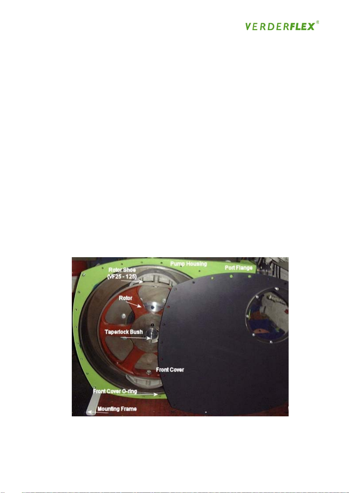
As indicated in Figure 1, the VERDERFLEX pump unit is one of the most simple, yet most robust
designs of its type, with very few actual moving parts:
Figure 1
The pump housing is terminated with DIN PN16 flanged connections (optional ANSI / JIS and
hose-tails (hose barbs) on VF10 and VF15 units). Within the housing is a rotor and two rotor
shoes. This assembly is rotated, causing the shoes to compress the reinforced hose, which
displaces liquid to generate the pumping action.
14
Page 15
The housing provides support for the hose whilst under compression from the shoe / rotor
assembly. A flange / insert mechanism is used to retain the hose position within the housing.
The flange uses a split collet design to clamp and seal the hose in the casing. The rotor runs in
a lubricant bath, which is filled either through the inspection cover or via a pipe at the rear of the
housing. Overall the unit is designed to enable simple assembly and maintenance
The pumps can be coupled to the drive gearbox motor unit in 2 different ways; either close
coupled (direct) or long coupled. The following is a brief description of the 2 variants.
Close-coupled design
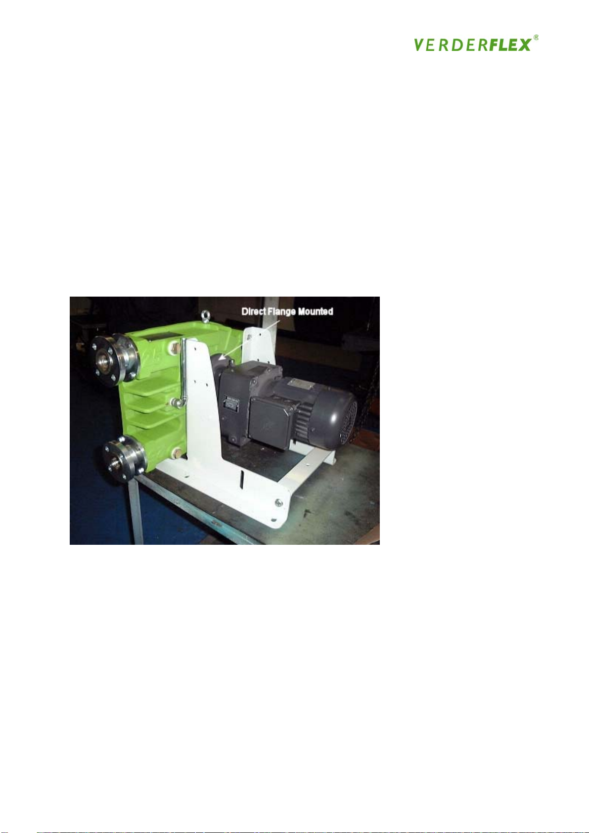
The gearbox/motor unit is directly attached to, and supported by, a flange mounting at the rear of
the housing (Figure 2). The rotor and shoe assembly is fastened to the gearbox output shaft via
a taper lock bush
Figure 2
Long coupled design
A bearing housing assembly is directly attached to, and supported by a flange mounting at the
rear of the housing (Figure 3). The rotor/shoe assembly is fastened to the bearing housing
assembly output shaft via a taper lock coupling. The gearbox/motor unit is supported by a base
plate, which forms an integral part of the frame, and is attached to the bearing housing assemblyinput shaft via a coupling.
15
Page 16
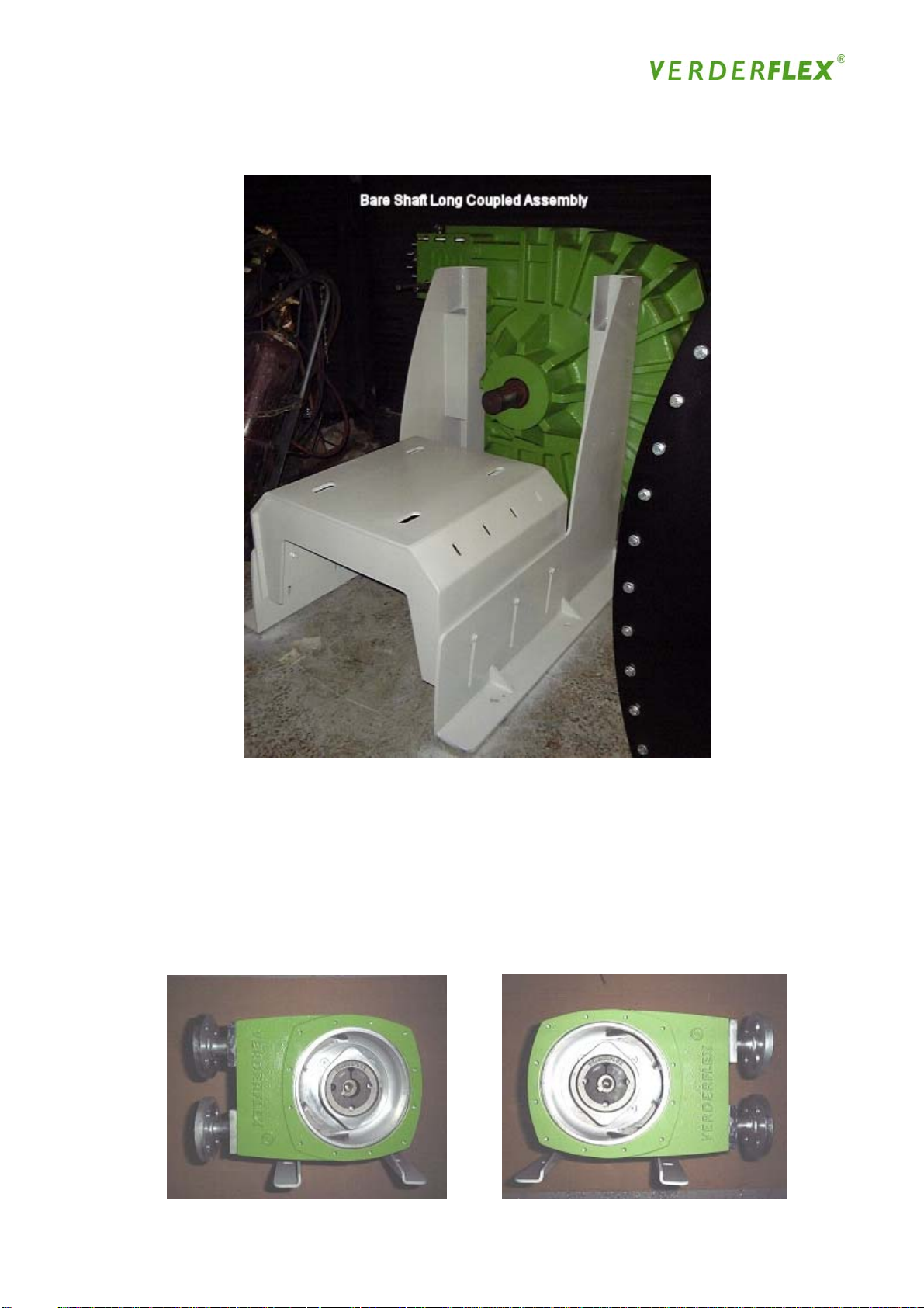
Figure 3
Mounting Options
The assembled housing is mounted on a support frame in any one of four positions (as indicated
in Figure 4). A change in direction of rotation can give the option of using both flange
connections as either suction or discharge ports
Figure 4
(1) (2)
16
Page 17
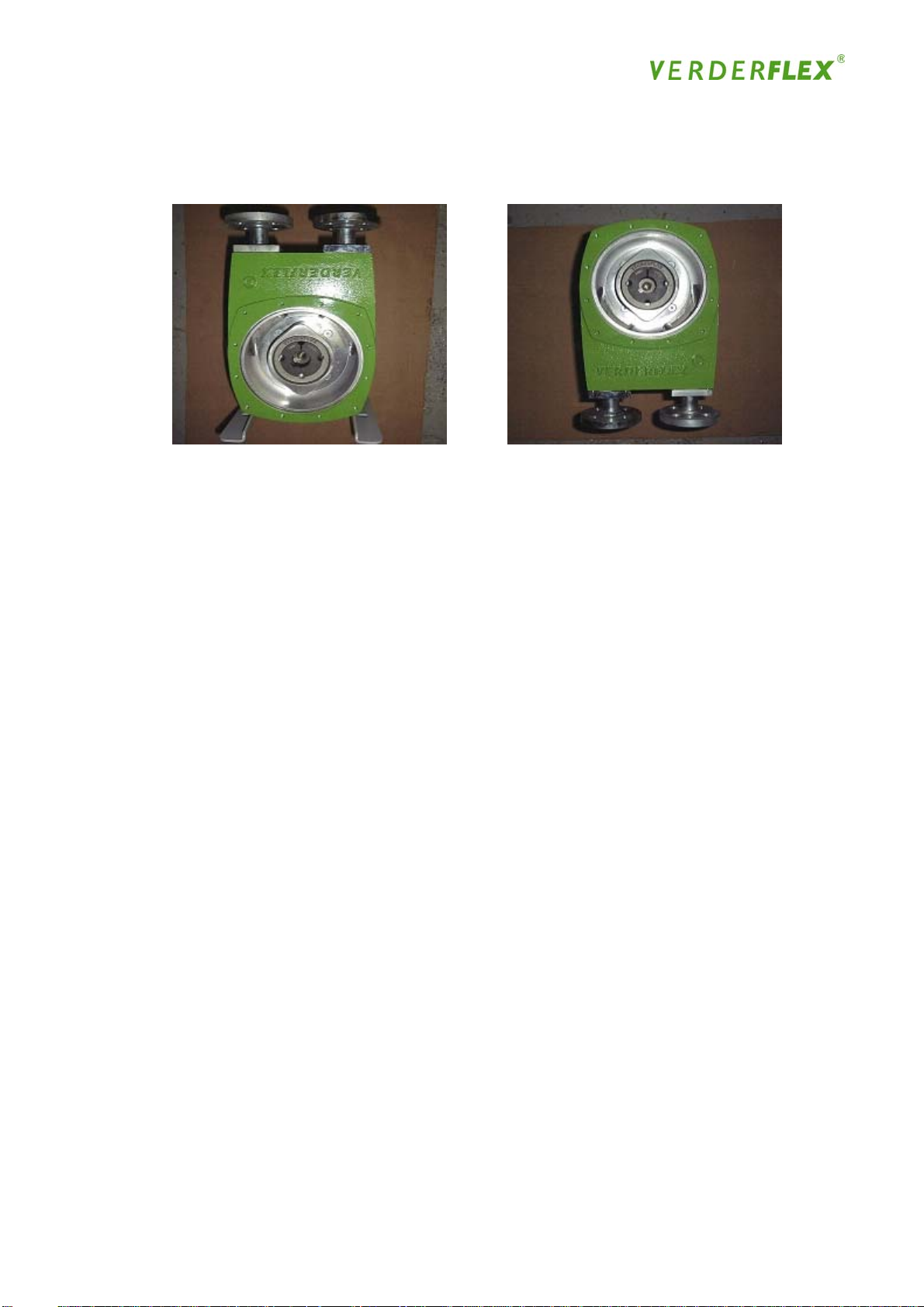
Figure 4
(3) (4)
3.6 Limitations of the Pump
VERDER is strongly committed to the belief that the customer must always be given as much
information as possible in order to make the best possible pump selection. For this reason the
list below contains details of the few VERDERFLEX limitations:
• Hoses are available in Natural Rubber; Nitrile Buna rubber; EPDM rubber & CSM (Hypalon
Ò). This selection is suitable for the majority of applications, but there remain some products,
which are not compatible with the hose material;
• Hose pumps often appear bulky and large in size when compared to other positive
displacement pumps with moderate flow rates;
• When compressing the hose, the overall volume of the sliding shoe causes the volume of the
suction line to be transferred to the discharge line, temporarily stopping the flow in both the
suction and discharge lines;
• Pulsation dampeners are needed occasionally as an accessory if:
o the lines are hammering;
o lines are smaller than size of pump
o the process is hammering;
o lines are long
o severe pulsation is noticed;
o product as a high SG
• The capacity of the pump may drop below nominal due to high impulse losses on the suction
or discharge side:
o The maximum impulse loss possible on the suction side is 40 kPa/6 PSI;
o The maximum impulse loss possible on the discharge side is 750 - 1200 kPa/105 -
170 PSI, dependent on the pump type
17
Page 18

3.7 Pump Selection
Pumps can be used to deliver higher capacities and are recommended for intermittent use only
to enable the dissipation of heat, which is generated by high speed and pressures. The actual
capacity of the pump depends upon the speed at which the rotor revolves. The pump’s speed
and consequent output achieved will depend on many factors:
• Is the medium being pumped aggressive, abrasive, viscous or shear sensitive?
• What type of use is required for the pump, all day every day or short, periodic use?
• Is the system a high or low-pressure system?
• Is the medium being pumped at a high or low temperature?
• What is the solid content - percentage of solids, shape and size of particles?
All these factors should be taken into consideration when selecting the pump size and speed of
operation. If you have any reservations, do not hesitate to contact your local VERDER
distributor, who will be more than pleased to offer professional, expert advice and
recommendations to ensure you get the optimum pump for your application
3.8 VERDERFLEX Hose
To complement the hose pump, VERDER has developed the VERDERFLEX hose for continuous
operation. Tests have shown that these hoses have significantly greater serviceable life in
comparison to materials used in competitors’ hoses, and are able to achieve a 95% vacuum
(equivalent to a suction lift of 9.5m)
18
Page 19

4. Safety, Operation and Maintenance Instructions
4.1 General – tools and facilities
Care should be taken at all times to ensure that any tools are used safely for the purpose for
which they are designed and in accordance with the manufacturer’s instructions. Ideally the
pump should be installed using a drive, with facilities to inch the pump along and which is able to
operate in reverse. Any maintenance work will require a complete set of metric spanners, a
socket set and torque wrench; you should check your fastener kit to ensure you have all the
correct sizes available
Specialist lifting equipment will be required for several of the procedures below (large size pumps
only: VF25 - VF80). The lifting equipment to be used should be checked for suitability for the
task and capability of lifting the combined weight of the pump components. Always follow the
manufacturer’s instructions for safe operation of lifting equipment (See Appendix C for guidance)
Pump sizes & weights
Pump Size Weight CC kg Typical CC Built Weight kg
VF25 73 110
VF32 106 160
VF40 196 250
VF50 240 320
VF65 750 975
VF80 850 1100
VF100 2000 2350
VF125 2800 3150
4.2 Assembly
VERDERFLEX hose pumps are sold around the world and are designed to be transported in a
compact flat-pack, ready to be assembled in the destination country. Under normal
circumstances your VERDER distributor will assemble the pump, but should this not be the case
for any reason, you should follow the following procedures:
19
Page 20
4.2.1 Preparation
• Prepare the workspace in which the pump is to be built, ensuring there is a clean and level
work surface with sufficient room for not only the pump, but also to allow you sufficient access
to the pump and fit pipe work, etc
• Carefully open the packaging and check for completeness by ensuring all the parts listed are
present (see the exploded view drawings and parts list at the back of this manual); remove all
the loose components and set them out on a workbench. It is recommended that the
fastener kit is sorted into piles of like items and kept in a safe place to avoid losing parts or
using an incorrect part
• If the pump casing or any parts are found to be damaged / wrong spec or missing, then you
should record the appropriate serial number from the casing ident. plate and/ or the quality
check seal on the packaging, and inform VERDER Ltd
4.2.2 Close/Long Coupled Pump Unit Assembly
• Carefully disassemble the box sides to leave a pallet, on which the pump should be
assembled ready for onward transport
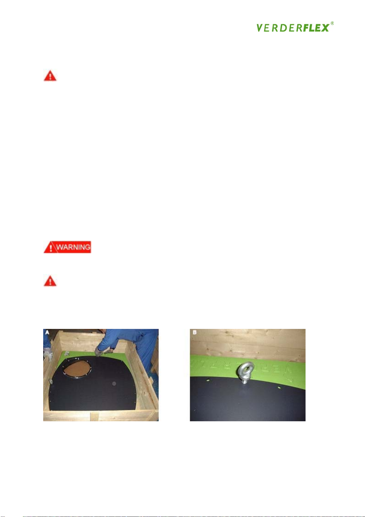
• Fit the lifting eye to the pump housing and lift until it is supported in the vertical position
• Completely remove 3 of the four bolts (VF10 - VF40) or nuts from the studs (VF50 - VF80)
leaving the 1 remaining nut or bolt loosely in place to retain the front cover in position
Figure 5a
A - Preparing for front cover lift by fitting lifting eye bolts
B - Lifting eye bolt fitted into 1 of 2 available tapped front cover bolt holes
20
Page 21
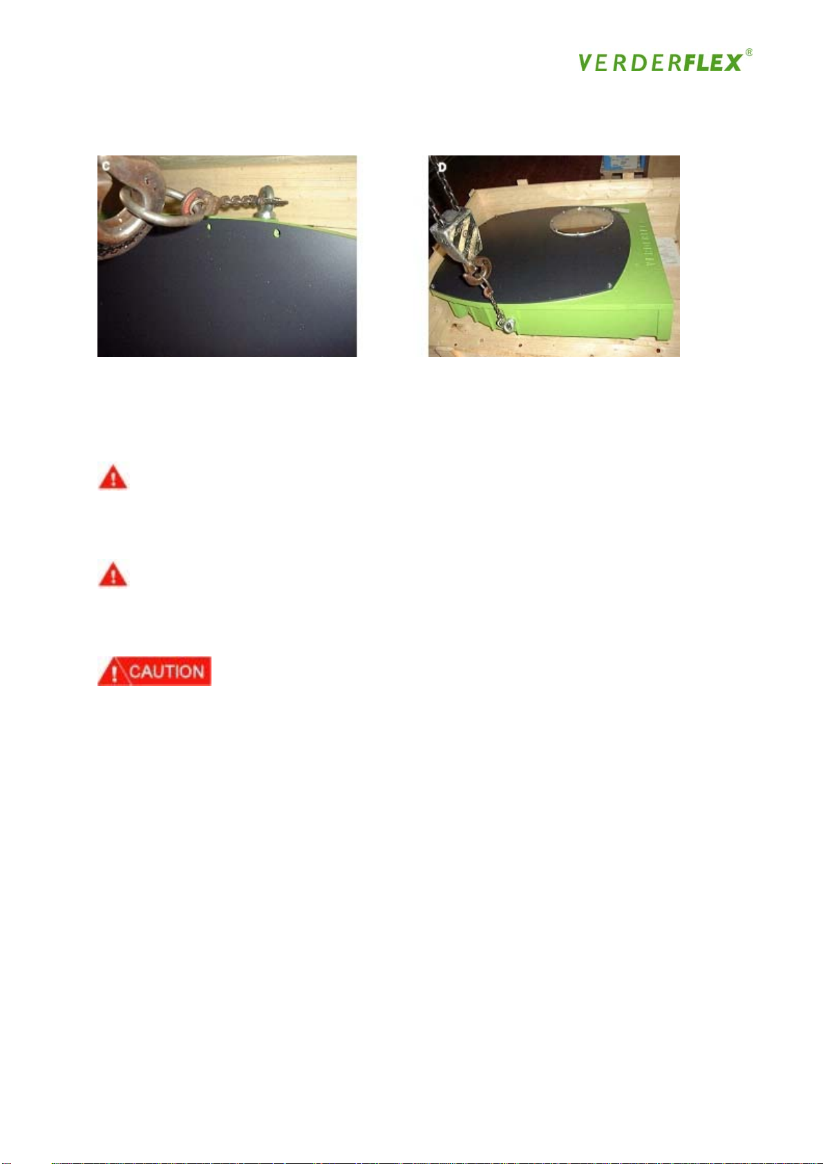
Figure 5a
C - Utilising 1 of 2 available pump case tappings to use a lifting eye bolt
D - Casing assembly being lifted to the vertical position with the eyebolts at the top end to
assist front cover removal and prevent damage to the studs
• Lift off front cover by utilizing case lifting eye and placing in threaded lifting hole (Fig.5).
• Remove the drive flange gasket
• Remove the rotor from the housing with the use of suitable lifting equipment
• Remove any remaining spares from the housing
• Using the lifting eye and suitable lifting equipment position the housing onto the edge of the
pallet, with the front facing down, as shown in Figure 6
21
Page 22
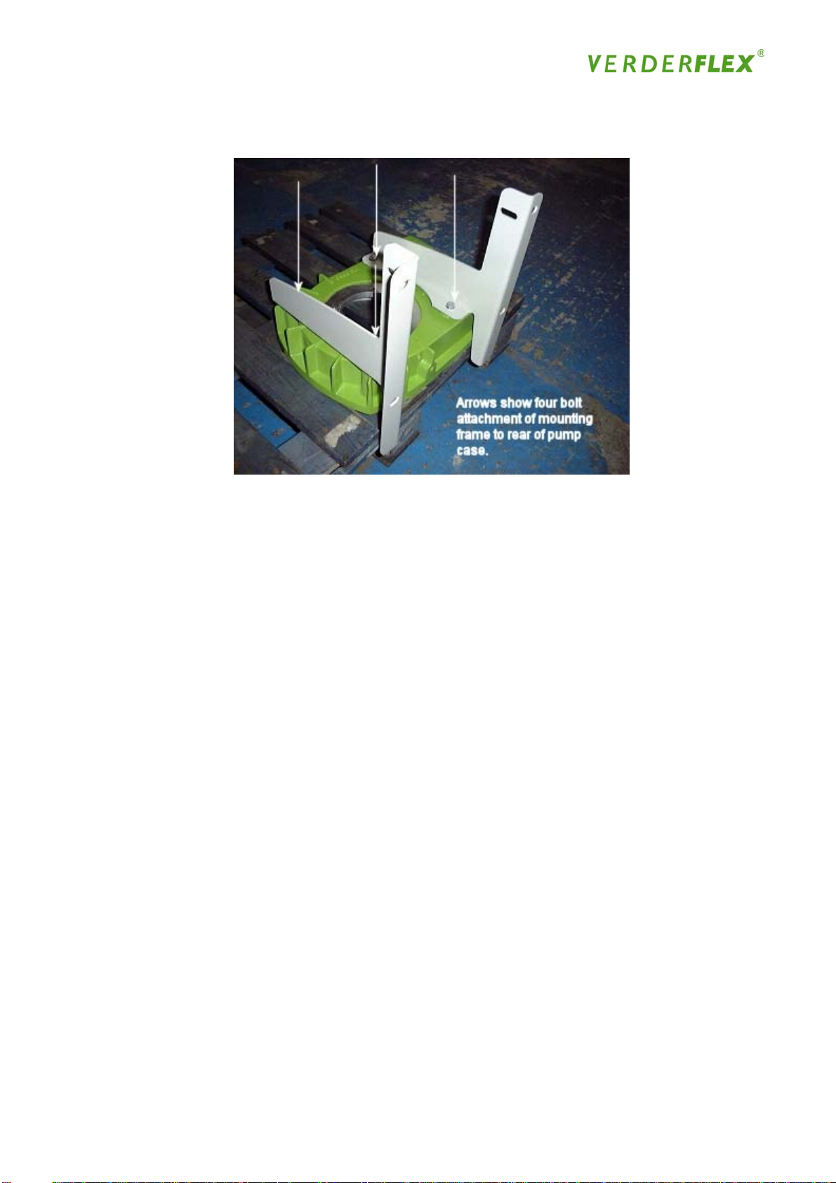
Figure 6
• Lift the side support frames into position, ensuring that the foot section of the frames have the
fixing holes on the outside, and bolt to the pump housing. Do not fully tighten at this stage
• Present the cross-members to the support frames (VF25 –80 only) and bolt into position,
tightening evenly at the same time as the frame/pump housing bolts. Refer to the torque
settings in “ Parts List ”
Note: With long coupled pumps the base plate replaces the cross-member
22
Page 23
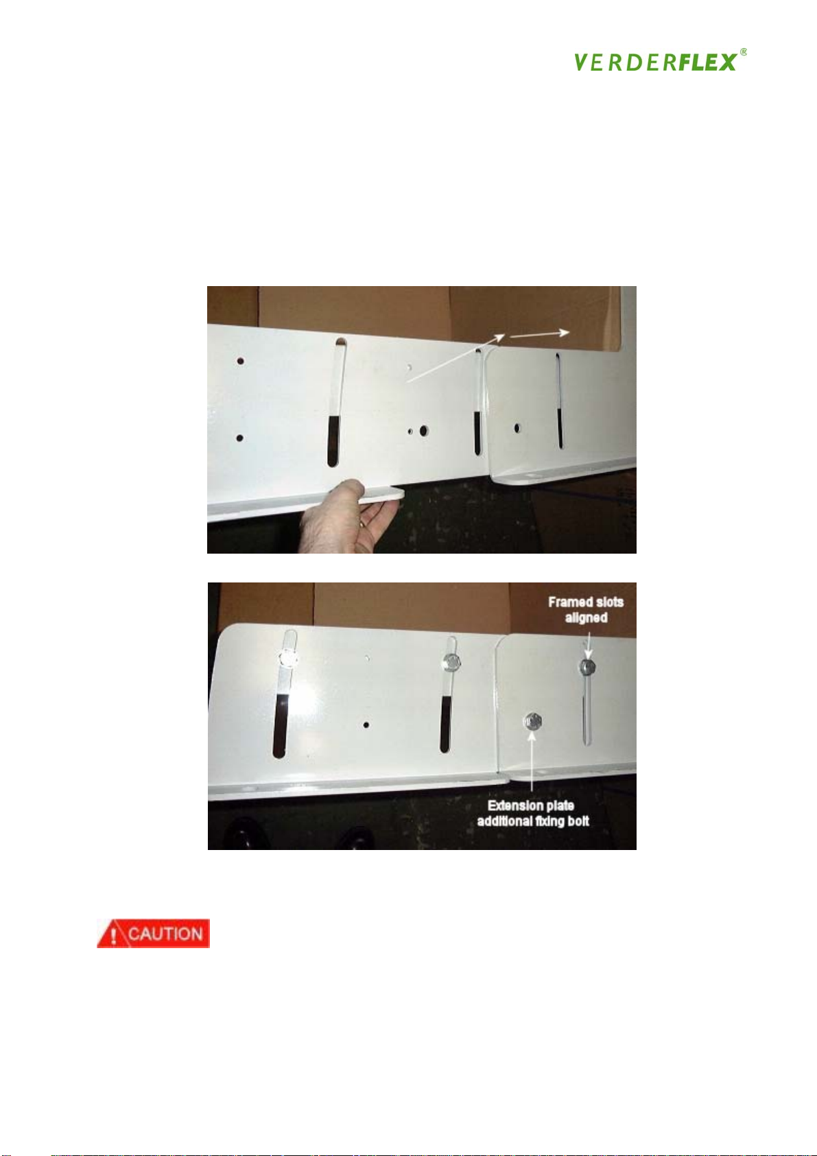
Long Coupled Mounting Frame Assembly
On VF10 to VF50 LC pumps, a mounting frame adaptor kit is needed to convert the closecoupled frame into a long coupled frame and yet maintain the current long coupled footprint.
The centre floor-mounting hole becomes redundant but can be used for additional fixing. The
assemblies are simple bolt on parts of which an example is shown in figure 7a / 7b below
Figure 7a
Figure 7b
Figure 7b shows the extension plate in place and the slots aligned to accept the base plate
mounting bolts.
• Lift the pump upright to stand on its frame using the lifting eye provided and the appropriate
lifting equipment
• The flange should be coated with a thin protective film of anticorrosion treatment, this does
not need to be removed before fitting the gasket. (if the pump has been cleaned during
preparation then a light film of grease or gasket sealant should be applied)
23
Page 24
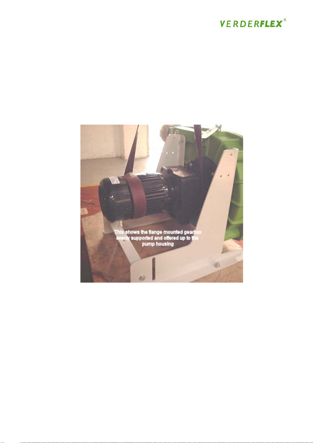
Mounting the gearbox
Close-coupled assembly
• Using the appropriate lifting equipment, to ensure the correct lining up of the gear motor unit
to the housing flange it is important to ensure that the gear motor unit is in the correct position
on the sling, both horizontally and in relation to the fixing holes
Figure 8
• Once the gear motor unit and the pump housing flanges are lined up correctly the fixing bolts
and washers are pushed into position. The bolts are positioned so that the bolt head is
situated inside the pump housing
Note: The washer under the bolt head should be replaced with a copper or nylon washer if a
vacuum unit is to be applied
• Fit the 4 nuts and washers on to the bolts and tighten the nuts evenly to the required torque
settings in Appendix D
Rotor Assembly
• Take note of measurement across the NARROW part of the shoe (VF10/15 only)to ensure
correct rotor setting in accordance with the table on page 26
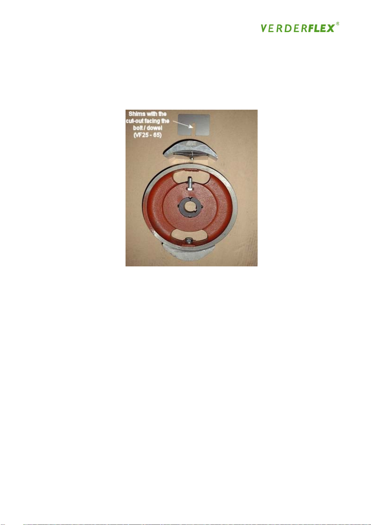
• Take the rotor shoes and tap the split dowels into position, then loosely bolt the shoe onto the
rotor
24
Page 25
Note:
1
This does not apply to VF10 and VF15 pumps as the rotor’s design incorporates the shoe
profile.
2
The VF80 does not have a split location dowel but instead has 2 bolts
Figure 9
• Check the shimming table, to ascertain the correct number of shims for each shoe to produce
the required flow at the required pressure, at the speed the pump is to operate
• Insert the required number of shims under each shoe and tighten the bolts to the correct
torque setting in “Parts List”, ensuring that the shoes and shims remain aligned correctly with
the rotor See Figure 09
Note: The shims must be inserted from the front edge of the rotor to enable shims to be removed
without taking the shoe off the rotor
• Clean up the output shaft and key with a piece of suitable emery cloth to ensure the rotor
slides on to the shaft with relative ease
• Loosen the Allen bolts in the taper lock bush fitted to the rotor. Remove one of the Allen
bolts and insert it in to the jacking position, then slowly rotate the screw clockwise to release
the bush slightly from the rotor, but do not remove the bush fully from the rotor
25
Page 26
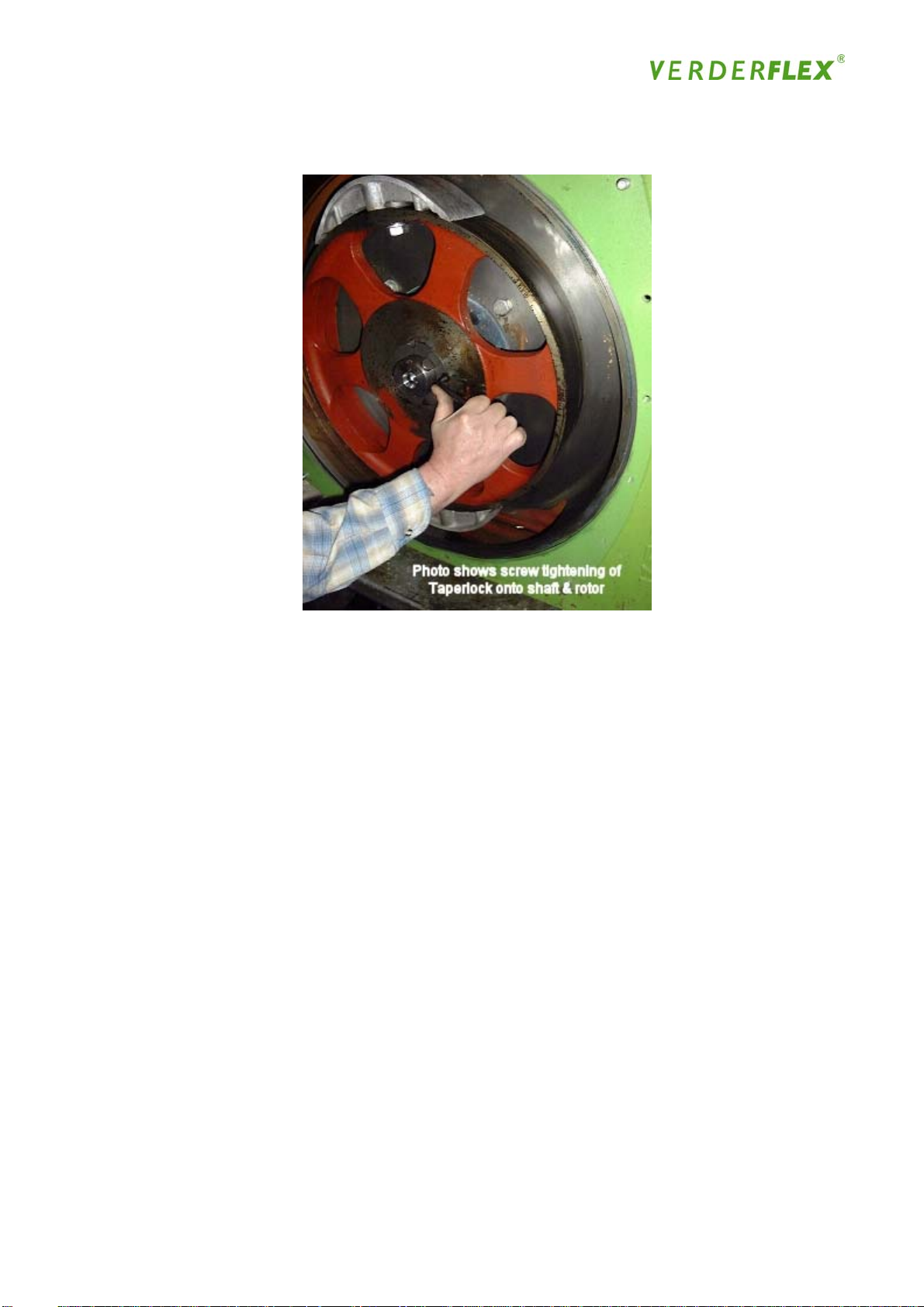
Figure 10
• Position the rotor at the front of the pump, with the use of the appropriate lifting equipment, so
that the taper lock screws are facing forward, away from the pump. Locate the rotor on to
the output shaft and push the rotor on to the shaft ensuring that the shaft key remains in
position, and tighten See Figure 10
Note: The taper lock bush is a standard Fenner part, which can be changed to fit different
diameter output shafts
• To ensure the rotor shoes are centred on the hose, once the pump is running it is necessary
to locate the rotor correctly on the output shaft. The distance required between the rotor and
the front cover is set out below:
Rotor Distance Set Dimension Table
Dimensions VF10 VF15 VF25 VF32 VF40 VF50 VF65 VF80
(mm) 4.0 4.0 12.0 11.0 11.5 11.0 18.5 21.5
(inches) 5/32 5/32 1/2 15/32 15/32 15/32 11/16 13/16
Note: Depending on the model of pump that is being assembled you can either use two metal
engineering rules or a long metal straight edge and an engineering rule, to set the rotor distance
correctly (see fig.11)
26
Page 27
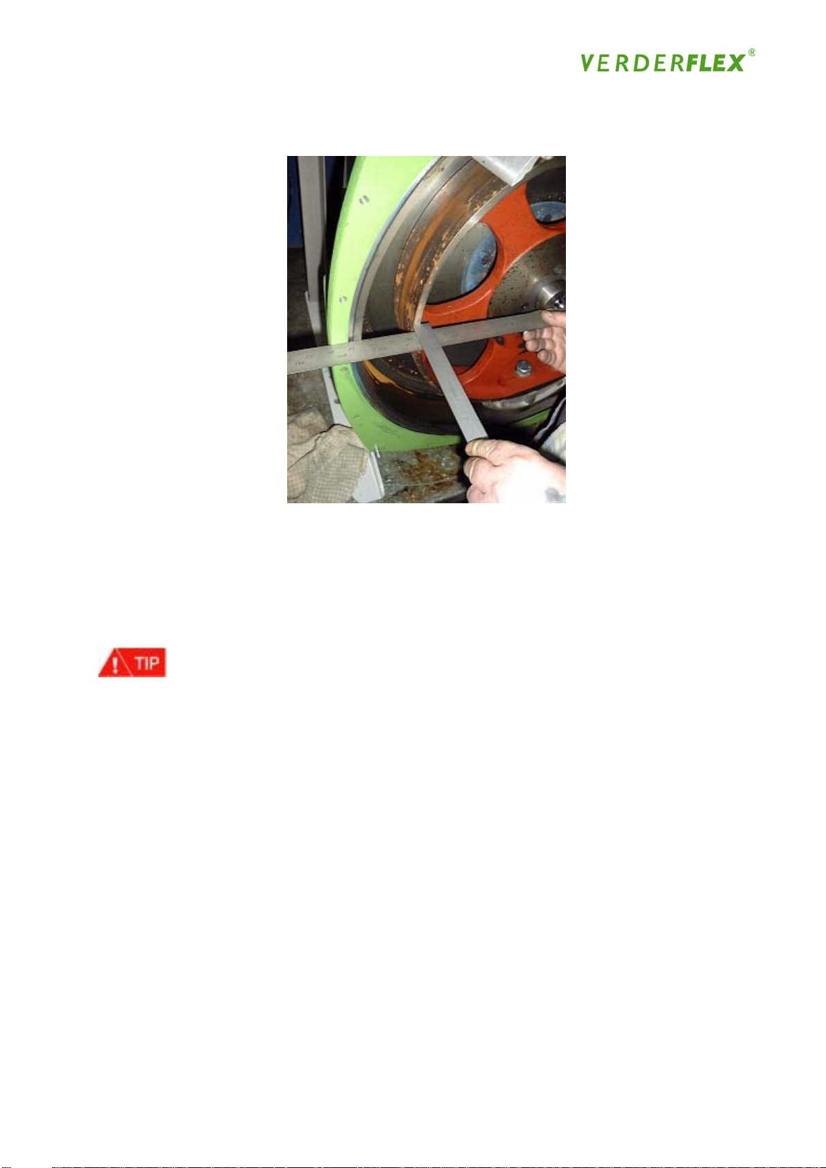
Figure 11
• Align the first rule/straight edge against the machined front of the pump housing, then take
the other rule and hold it perpendicular from the outer edge of the rotor (not the shoe) and the
first rule/straight edge (see Figure 11). With the use of a soft-faced hammer, tap the
rotor/bush on to the shaft until it is positioned correctly to give you the required setting
distance (see table on page 26)
• When the taper lock is tightened up it tends to pull the rotor forward, therefore you need to
take this into consideration when setting the distance
• When the correct distance has been achieved insert the Allen bolt back into the fixing position
and tighten the Allen bolts to the correct toque setting
• Re-measure the setting distance to ensure the rotor has not moved in excess during the
tightening of the taper lock bolts
• Lightly grease the O-ring groove on the machined front of the pump housing - not the total
machined face - and place the front cover O-ring in position (the grease is simply to keep the
O-ring in position during assembly)
27
Page 28
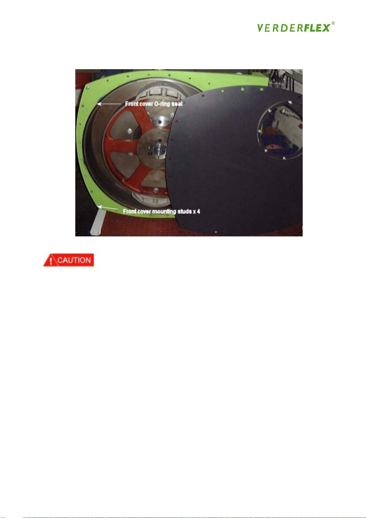
Figure 12
• Lift the front cover into position onto the 4 corner studs (shown in Fig 12), with the use of the
lifting eye and appropriate lifting tackle, and hand tighten the four corner nuts (removed
earlier). Hand tighten the rest of the front cover bolts, remove the lifting equipment and
replace the lifting eye with the remaining front cover bolt. Work around the front cover
tightening all the bolts evenly (in a criss-cross sequence) to the required torque setting in
“Parts List”
Drain & Filler Plugs
• Line the thread of the breather tube with PTFE tape and tighten into position to give a leak
free seal
28
Page 29
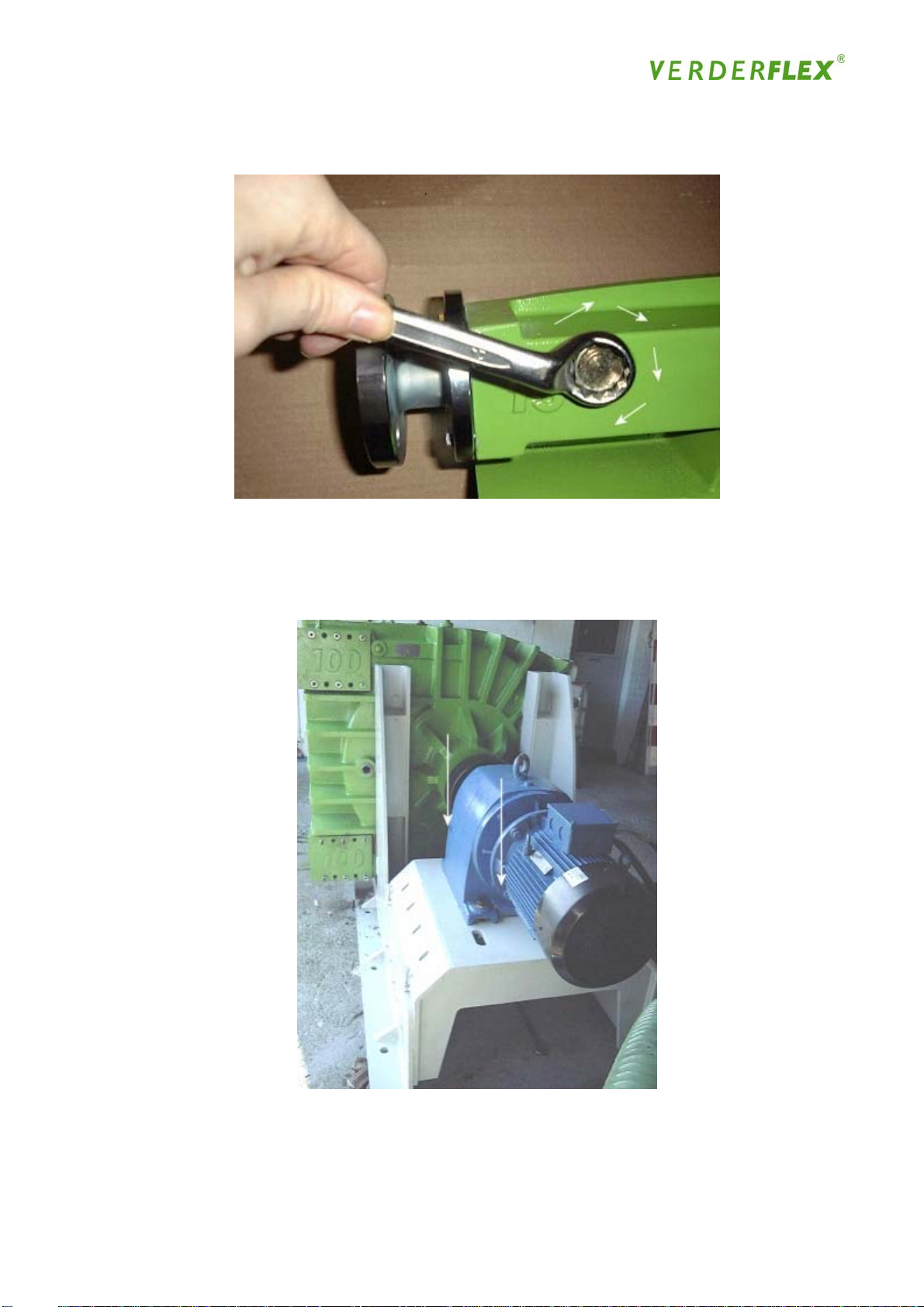
Figure 13
• Fit the two drain plugs (Fig.13) with the nylon washers and tighten into position to the
required torque setting in Parts List
Figure 14
Arrows show long coupled drive (floor mounted gearbox fittings)
29
Page 30

4.3 Installation
Prepare the workspace in which the pump is to be installed, ensuring there is a clean and level
work surface with sufficient room for not only the pump, but also to allow you sufficient access to
the pump for maintenance purposes and fit pipe work, etc
Lift the pump & gearbox assembly using the appropriate lifting equipment referring to the weights
table (chapter 4.1) and eyebolt-lifting guide (page 81)!
The power supply and control panel should be installed. If the pump is to be operated remotely,
a separate control panel with STOP and START facilities should be installed near the pump, but
at least 3 metres / 9 feet distance from the pump
Pipe work should:
• Be as short and direct as possible;
• Be oversized, especially the suction line;
• Be aligned correctly, free from stress and securely anchored;
• Include a short, removable section adjacent to the port flanges to allow easy access when
changing hoses, ideally this should be a flexible non-reinforced hose;
• Include suction and discharge valves (if a discharge valve is fitted, a high pressure safety
device will also need to be installed to prevent excess pressure building up when discharge
valve is closed with pump running);
• Include drainage taps to allow safe removal of product;
• Include a minimum number of turns and long radius elbows where change of direction is
necessary;
• Not be undersized
To install the VERDER hose pump, follow the procedures below:
Lift the pump into position and bolt to foundations securely, ensuring that the pump and drive
assembly is supported to enable a balanced, vertical lift
Only a qualified electrician should carry out this task
• Connect the motor to the power supply, following the manufacturer’s instructions. Pay
attention to the direction of rotation of the pump when wiring the motor
• If not already fitted, install the hose following the procedure described in Section 4.6 on ‘Hose
Installation’
• To improve hose positioning on installation & removal, the incorporation of an additional
facility in the form of a forward/reverse and inch control.
30
Page 31

Check compatibility of the hose material with the product being pumped – this should have been
verified by your distributor
• If not already shimmed, shim the pump according to the operating pressure required,
following the procedure described in Section 4.6 on ‘Shim Installation’;
• Check the level of lubricant;
At all times the pump housing needs to be between one third to one half filled with
VERDERLUBE lubricant (this can be verified by use of an external lube level plug fitted to later
models*)
Check compatibility of the lubricant with the product being pumped; VERDERLUBE is a specially
formulated food grade lubricant containing glycerine. In most cases this is a very stable
compound, but can react when mixed with certain types of substance.
Do not use VERDERLUBE with nitrogenous compounds, concentrated acids or strong oxidizing
agents
If you are unsure of the chemical compatibility of your product with VERDERLUBE, your
VERDER distributor will offer advice and if necessary, supply an alternative such as
VERDERSIL, a silicone oil based lubricant
4.4 Commissioning
Check all nuts and bolts are tightened to the required torque settings in `Parts List`
• Before connecting the pump to pipe work, run the pump dry for 10 - 20 revolutions in both
directions to ensure that the hose is secured properly. Stop the pump immediately if there
are any leaks or other problems
• Connect the pipe work and tighten all fasteners securely
• Close all drainage taps and open all valves
• Start the pump running for 10 - 20 revolutions. Stop the pump immediately if there are any
leaks or other problems
• Test pump for leaks and back flow at operating pressure and correct flow rate, as it may be
necessary to adjust shimming
31
Page 32

4.5 Operation
The pump should only ever be used for the purpose for which it is sold.
For normal continuous operation the pump speed should not exceed the speeds in the following
table, unless expressly advised by your VERDER distributor:
VF10 VF15 VF25 VF32 VF40 VF50 VF65 VF80
75rpm 75rpm 100rpm 90rpm 75rpm 60rpm 50rpm 40rpm
Operating pressure should not be altered to operate outside the tolerances recommended by
your VERDER distributor
When the pump is running, you should not touch the pump and should maintain an adequate
safe distance from the pump
Do not climb onto / on the pump or connecting pipe-work
Never place hands or other parts of the body inside or near any part of the pump when it is in
operation or when the power is not totally isolated
Maintain a clean environment around the pump. The VERDER pump is manufactured from cast
iron, flanges etc and therefore may have sharp edges - slipping or falling against the pump may
cause serious injury
Wear safety clothing (hats, gloves, boots, etc) when operating or working on the pump or in its
immediate vicinity
32
Page 33
4.6 Maintenance
It is good practice to wash down the external surfaces of the pump prior to carrying out any
maintenance operations. This will prevent the interior of the pump being contaminated with dirt
or debris
4.6.1 Hose - Removal and Installation
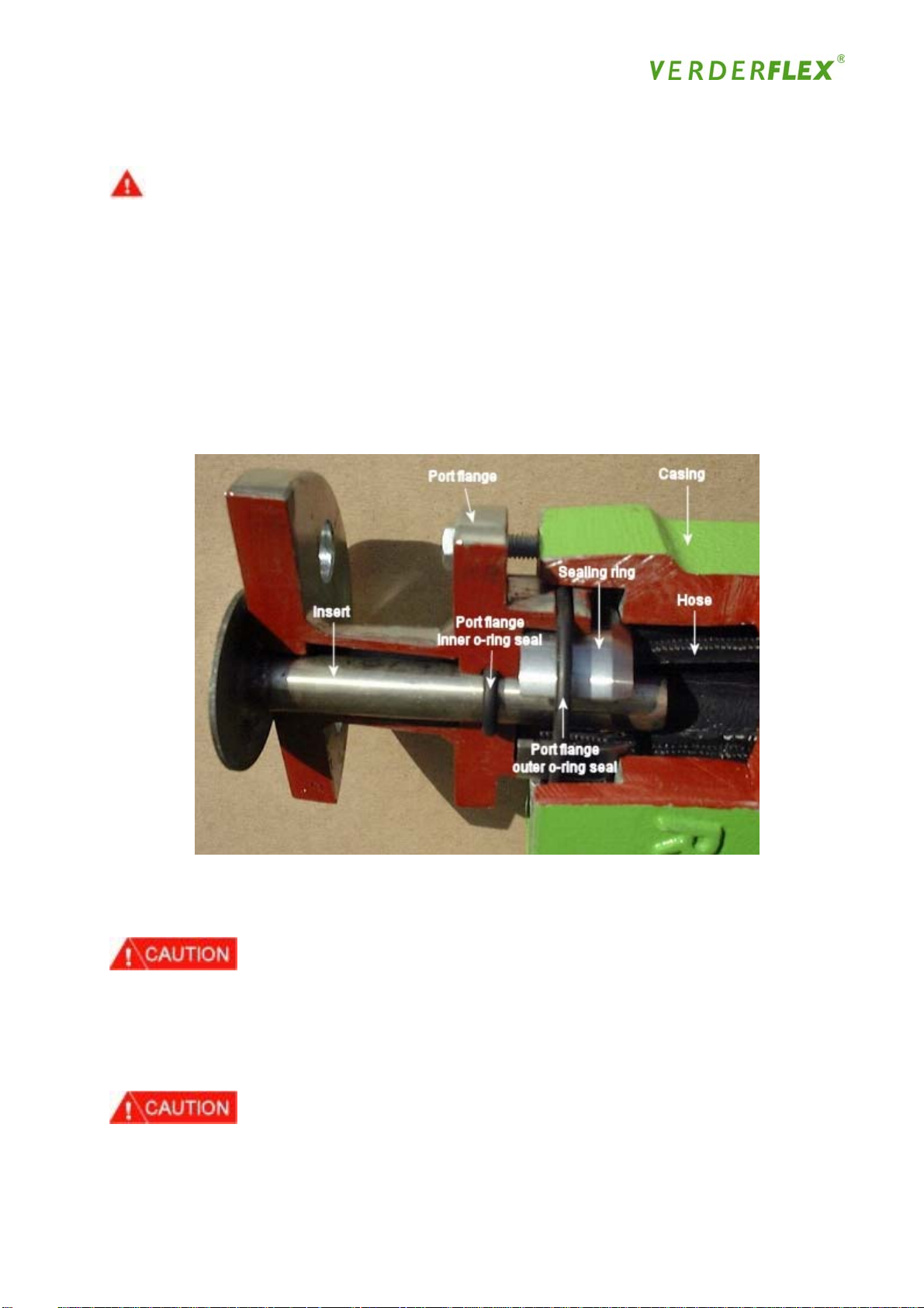
This procedure involves removal and reinstallation of the port flange assembly - installation of the
port flange assembly automatically clamps the hose to the insert and seals the flange with the
pump housing. You should study the sectional photo figure 15 below in detail
Figure 15
4.6.2 Hose Removal
• Stop the pump drive and isolate electrical supply
• Close Inlet and then Outlet valves on pump piping
• If fitted, drain the remaining product from the inlet and outlet pipeline drain taps being aware
that there will be some internal pressure and taking care to handle the product appropriately
Always follow the safety procedures for handling and disposal of the product being pumped
33
Page 34
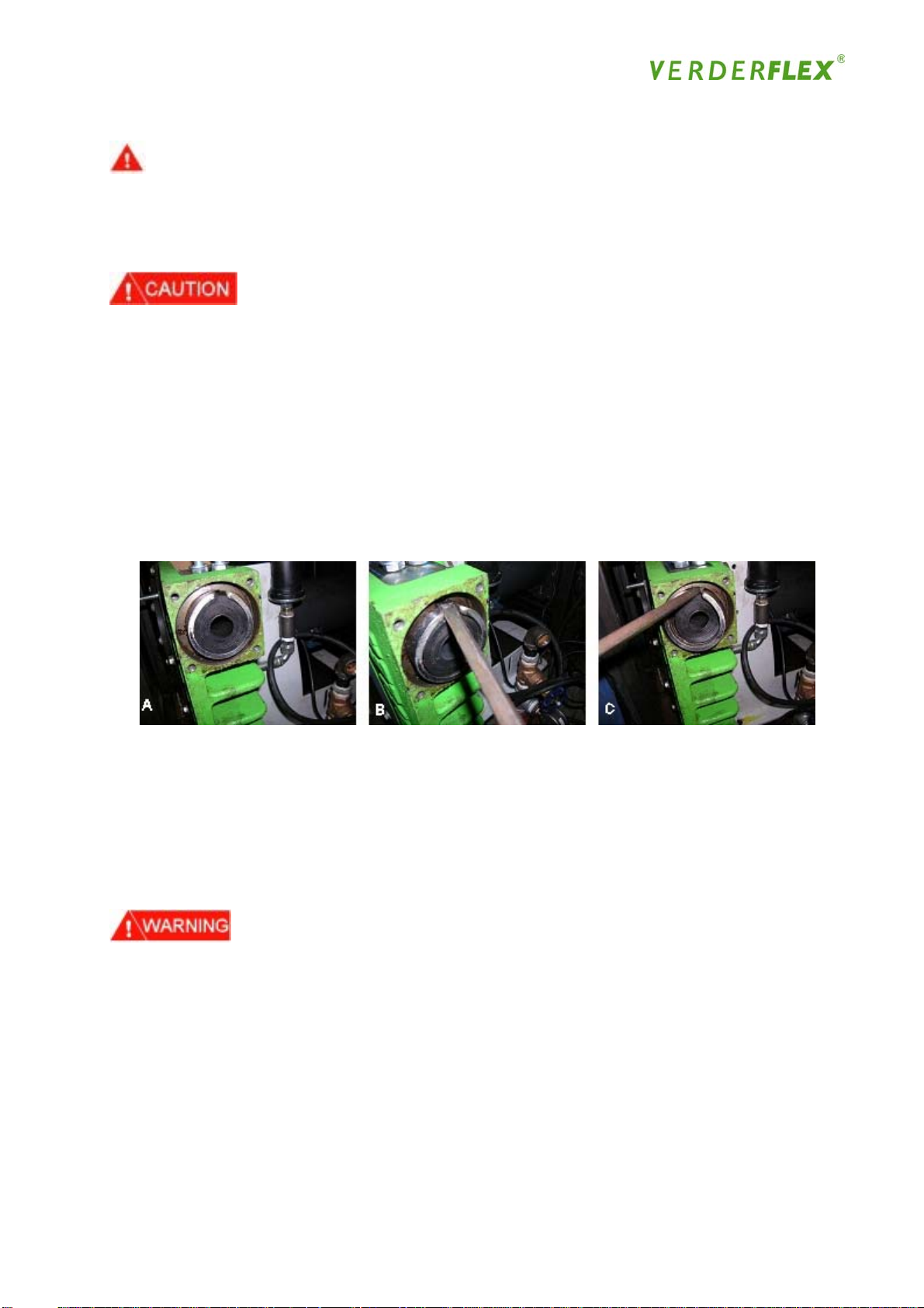
Loosen the lubricant drain plug, and slowly let the lubricant drain into a container for re-use or
disposal (lubricant should not be re-used if it is contaminated with the product). Replace the
drain plug when all lubricant has drained from the pump housing; check the condition of the
sealing washer
If the hose has ruptured, the lubricant may be contaminated with the product - care must be
taken to handle the mixture appropriately. It is not advised to re-use the lubricant once the pump
has run for 24 hours
• Remove the section of piping immediately connected to both inlet and outlet port flanges to
allow access. Place a container below the port flange to catch any remaining lubricant that
may be still in the pump
• The inlet port flange is held in place with four bolts, which should be loosened and removed,
in a criss-cross formation
• Pull out the port flange assembly and remove the insert and clamp rings (see fig 16 below).
Figure 16
• Clean all parts and check the insert and O-rings for wear or other damage. Replace sealing
rings every 2nd or 3rd hose change (supplied as a ‘ Flange sealing kit’ including O Rings)
• Repeat the above step for the outlet port flange
• Reconnect the power to the drive and slowly inch the drive forward a short distance. Check
the hose is completely free at both ends, then continue to inch the drive forward slowly to
expel the hose
Do not stand near the pump during this operation. If the hose is expelled too quickly it could
cause serious injury
• Inspect the pump for any spillage of product. It is recommended that the pump housing
should be cleaned, typically using a water jet, following hose removal, particularly if:
(a) leakage has occurred; or
(b) the product is aggressive / corrosive;
• Inspect hose for wear and damage and maintain a record of its condition and hours of
operation
34
Page 35
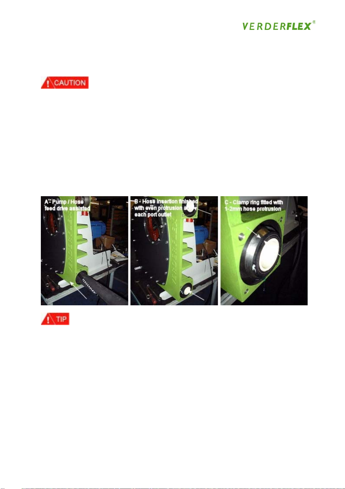
4.6.3 Hose Installation
Never try to install a hose without the front cover in place
• Rest one end of the hose in the mouth of the inlet port (the hose should be fed into the pump
in the direction of normal operation) and rub lubricant along the outer wall of the hose, feeding
it into the pump housing as each length of hose is lubricated. Once the hose reaches the
rotor, the drive can be inched forward to feed in the remainder of the hose. Continue to
lubricate the full length of the hose as it is fed into the pump
• The hose should be inched forward until there is sufficient hose protruding from the inlet port
to be able to fit the sealing ring, with the outer edge of the sealing ring positioned 1 to 2mm
inboard of the end of the hose. If the hose passes this point the drive should be reversed
and inched back into the correct position
Figure 17
• For accurate positioning of the hose it may be possible to manually rotate the rotor by
isolating power first then removing the cooling fan cover and turning the fan by hand. This is
not always possible with the larger pumps
• Fit the sealing ring, long tapered edge first, over the hose
Note: The sealing ring of the VF10 - 40 is tapered on one edge only and is fitted toward the
pump! The VF50 - 80 is tapered on both edges. The end of the sealing ring should be 1 to 2mm
inboard of the end of the hose (see fig 17)
• Place the sealing ring over the hose and then the port flange, hand tighten the four bolts into
the pump housing:-
35
Page 36
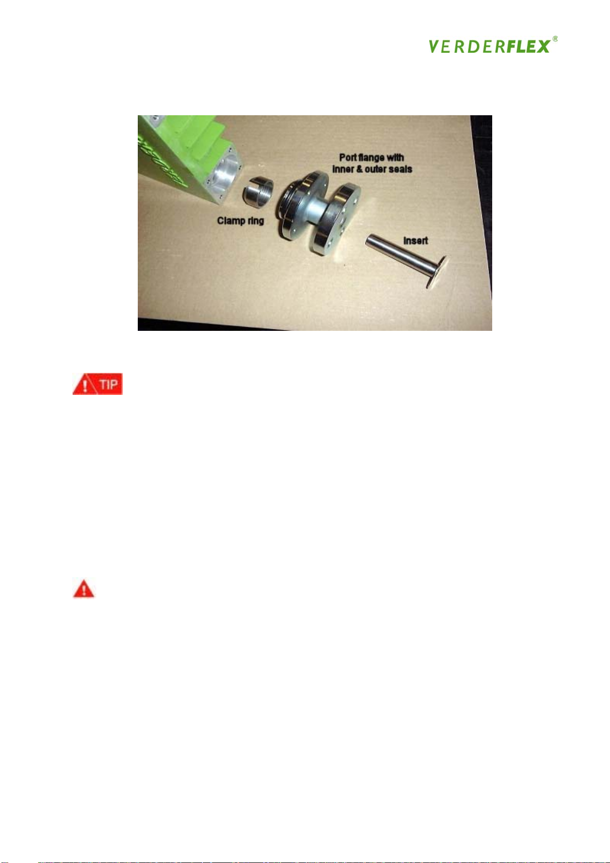
Figure 18
• Position the insert in the port flange and gently ease into the hose;
Use a small amount of lubricant if necessary on the insert and inner part of hose.
• The port flange bolts must be tightened up evenly - it is important the flange is presented
evenly to the pump housing, otherwise the sealing ring will not clamp the hose correctly. The
first bolt should be tightened for two turns, followed by two turns for the bolt diagonally
opposite - repeat this for the bolts on the other diagonal (see Fig.19)
• After all four bolts have been tightened for two turns, tap or clamp the insert into the port
flange using mole grips, bolt /nut and washer the size of the output flange (see fig 18) or by
bolting all of the customer flange to the port flange to maintain its position. It is important
these two tasks are co-ordinated otherwise the assembly will not seal correctly. Repeat this
procedure until all bolts are tightened to the required torque settings in `Parts List’
• Because of the use of helicoil inserts on VF10 & VF15 Aluminium casings, care should be
taken when tightening the steel port flange bolts so as to avoid accidental stripping of the
thread
36
Page 37
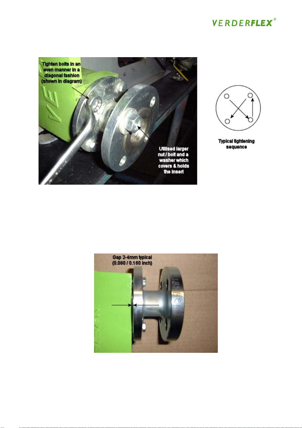
Figure 19
Note: With the four bolts tightened up to the correct torque loading there should be a gap
between the port flange and the casing of typically 2-6mm, as shown in Figure 20. It must be
noted that the relationship between correct torque and finish gap can vary due to component
tolerances. The effort to reach the torque should not override this as the torque figure is a
maximum figure and not the minimum requirement. The important factor is to achieve sufficient
clamping of the hose. Do not over tighten to bring the port flange flush against the casing as this
will result in the bolts shearing
Figure 20
37
Page 38

• When the inlet port flange is fitted, it may be necessary to inch the drive to rotate the pump in
the forward direction or to slow run the pump to stretch/elongate the hose sufficiently enough
to feed the hose through the outlet flange to be able to fit the sealing ring in the correct
position, or to slow run the pump to stretch/elongate the hose
• It is normal for the hose to be initially under tension, as after approx. 7 days the hose will
stretch.
• Once the hose is in the correct position, fit the sealing ring and fit the outlet port flange,
repeating the procedure for fitting the inlet port flange and insert
• Check the drain plugs are tightened correctly, then fill the pump housing with the
recommended amount of lubricant - refer to Section 4.7 on ‘Lubrication’: check for any
leakage. (VF10 -15 will need to be filled through filler/ breather tube; for larger pumps it may
be quicker and easier to fill the lubricant through the inspection cover)
• Operate the drive forward for 10 - 20 revolutions to check the hose is securely clamped in the
inlet port flange assembly. It is recommended that a container is placed below the inlet to
catch the lubricant just in case the hose de-couples
• When satisfied, repeat with the drive in reverse for 10 - 20 revolutions to check the hose is
securely clamped in the outlet port flange
• When satisfied, check the pump is shimmed to the required level - refer to the shimming table
in Appendix A or alternatively to the section on ‘Shimming the Rotor shoes - Removal and
Installation’
Hose storage and shelf life
Shelf life for hoses is approximately two years for NR and NBR hoses, and approximately four
years for EPDM hoses. The hoses should be stored flat in a cool, dark location and should not
come in contact with any ultra-violet lighting, otherwise the product will be aged artificially
4.6.4 Inspection Cover Removal
Isolate power supply:
• Undo inspection cover bolts - take care to support the weight of the inspection cover whilst
removing the bolts
• Remove inspection cover and O Ring; take care when lifting the inspection cover
Inspection Cover Installation
• Clean the inspection cover with a non-scratching cloth
• Check the inspection cover O Ring for damage and replace as required.
• Installation is opposite of removal process with particular attention paid to using the torque
reference in the `Parts List’ to avoid damage and in particular cracking around the bolt holes.
The new inspection window is larger as it incorporates a machined groove to accept an O-ring
seal this design retains the original bolt configuration to enable it to retrofit existing pumps. The
seal sits proud of the surface and seals against the inside and the casing when tightened
38
Page 39
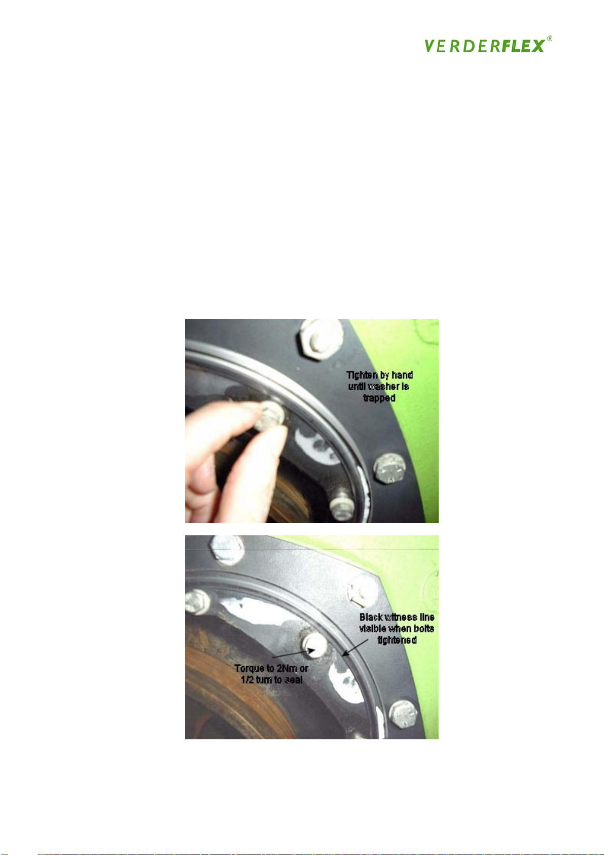
Installation:
As the new assembly has a machined o-ring groove it is susceptible to damage due to over
tightening therefore the instruction below must be followed:
• Clean the inspection cover with a non-scratching cloth as previous
• Position the window taking care to ensure the o ring seal is sat in the groove all the way
around before tightening.
• Tighten the bolt by HAND, until the plastic washer becomes trapped by the bolt head. Then
observe the relevant torque of 2Nm, if a torque wrench is not available then once the washer
is trapped the bolt head should be turned only ½ a turn more to tighten. The result in either
method is that you will see a witness mark through the plastic cover in the o-ring groove area
in respect of the seal turning from grey to black. This signifies the o-ring has created a seal
and does NOT require further tightening (see fig 21 below)
Figure 21
39
Page 40

Front Cover Removal
Never remove front cover when the hose is still in position. The hose must be removed following
the procedures in the section on ‘Hose Removal’
• If necessary fit the lifting eye to the front cover by removing the top left of centre fastening
bolt and screwing the eye in to the threads provided, then fit the appropriate lifting equipment
• Remove the front cover bolts and remove the front cover. Remove the front cover bolts and
the four nuts from the studs, and remove the front cover
Note: Take extreme care when lifting and removing the front cover
• Remove front cover O-ring
When removing the front cover, lifting equipment should be used to support the weight. Always
use lifting equipment safely in accordance with the manufacturer’s recommendations. The pump
is provided with a lifting eye, which can be fitted into the threaded holes of the front cover
(located in the top left of centre of the front cover underneath the bolts) to assist with lifting.
Take care not to drop the front cover as this is likely to cause serious injury
Removing the inspection cover will make it easier to manipulate the front cover; you should use
lifting equipment - follow the manufacturer’s instructions for safe operation of lifting equipment
4.6.5 Front Cover Installation
• Check the front cover O-ring for signs of damage and correct size. Lightly grease the O-ring
groove on the pump housing and fit the O-ring in to position
Note: Do not over grease the front cover O-Ring groove
• Installation of the front cover is the opposite of the removal procedure
4.6.6 Shimming the Rotor Shoe
The purpose of the shims is to achieve the required operating pressure & prevent back-flow or
slip at the minimum operating speed. Additional shims will increase the degree of compression
of the hose. You should study the photos (Figure 22) in detail
40
Page 41
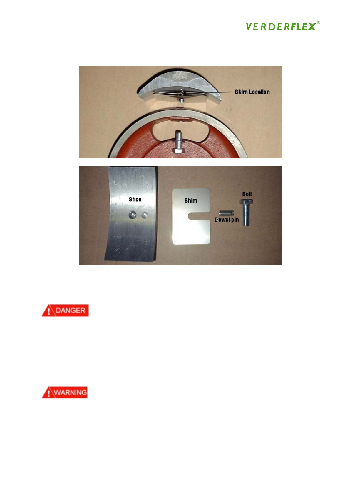
Figure 22 - Rotor Shoe Assembly & Component identification
4.6.7 Shim Removal
Isolate power supply
• Follow the procedure for the removal of the inspection cover
• If power is not available, remove the motor cover to gain access to the cooling fan & shaft, if
the fan is too tight to turn, then it may be removed to enable the rotor to be turned via the
shaft by using a strap wrench or special wrench
• Alternatively reconnect the power supply and inch the drive forward until the rotor shoe is
positioned over the open inspection hole
Do not stand within the immediate vicinity of the pump when operating with the inspection cover
removed; follow safety procedures for operation of pump with inspection cover off
41
Page 42

• Loosen the rotor shoe bolt(s), remove the shims and retighten rotor shoe bolt(s); the shims
are slotted to enable their removal without completely removing the bolt(s)
• Reconnect power supply and inch drive forward until the second rotor shoe is positioned over
open inspection hole
Do not stand within 3 metres / 9 feet of the pump when operating with the inspection cover
removed; follow safety procedures for operation of pump with inspection cover off
• Loosen the rotor shoe bolt(s), remove the shims and retighten rotor shoe bolt(s); the shims
are slotted to enable their removal without completely removing the bolt(s)
4.6.8 Shim Installation
• Take care to always isolate power before approaching or working on pump when inspection
cover is removed
• Installation is opposite of removal process.
Note: When tightening the rotor shoe bolt(s) ensure that the shims and the shoe remain correctly
aligned and are parallel to the rotor. Failure to do this will cause damage to the hose, resulting
in a detrimental effect on the life of the hose
4.6.9 Rotor Shoe Removal
Isolate power supply
• Follow instructions for the removal of the inspection cover
• Reconnect the power supply and inch the drive forward until the rotor shoe is positioned over
the open inspection hole
• Loosen the rotor shoe bolt(s), remove the shims
Care should be taken to support the weight of the rotor shoe whilst the bolt is being removed similarly care should be taken not to drop the shoe after removal from the pump housing
• Remove rotor shoe bolt and lift shoe out of pump house
42
Page 43

4.6.10 Rotor Shoe Installation (VF25 – VF80)
• Check the rotor shoe contact surfaces for any signs of damage and replace as required.
Any wear or roughened surface will seriously affect the performance of the pump. And also
reduce the life of the hose
• The installation of the rotor shoe is the opposite of the removal procedure
Before considering replacement of damaged shoes, any sharp edges and damage to non contact
areas can be blended out with fine emery / sandpaper
4.6.11 Rotor Removal
• First remove the hose
Isolate power supply
• Remove the front cover
• Secure the rotor with the appropriate lifting equipment and support the weight. Follow
manufacturer’s instructions for safe operation of lifting equipment
• Loosen the two rotor bolts (Allen) from the taper lock bush and remove one of them. Insert
this bolt in to the jacking position and start to turn clock-wise. When the rotor starts freeing
from the taper lock, and the bush’s clamping force on the shaft is released, stop turning the
bolt. This should now allow you to slide the rotor along the drive shaft towards you. If it
does not slide freely then it may be necessary to turn the jacking bolt again
Ensure that the weight of the rotor is being supported at all times during this procedure
• Remove the bush and rotor off the shaft in one piece, and place on a suitable surface
If the bush is difficult to remove from the shaft, prise open the bush once the rotor is released
Take care when removing rotor! As it comes away from the pump shaft, it will tend to swing out
on the lifting equipment, potentially causing serious injury - stand well clear
4.6.12 Rotor Installation
Installation is opposite of removal process but you should refer to Section 4.2 on ‘Assembly’ as a
further guideline
Bearing Housing
43
Page 44

4.6.13 Pump Shaft and Bearings Removal (Long Coupled Versions only)
• Follow procedures for the removal of the hose, front cover and rotor
• Before starting this procedure it is recommended that you purchase a complete set of
replacement parts (a bearing assembly - seal kit; drive shaft; Key kit and bearing kit)
Isolate power supply
• Remove the coupling guard and disconnect the coupling from the input shaft of the pump
• Remove bearing assembly from pump housing (it may be necessary to remove the gear
motor)
• Remove Allen bolts, sealing plate and sealing plate O-ring
• Remove front lip seal
• Secure pump shaft with lifting equipment and support weight. Follow manufacturer’s
instructions for safe operation of lifting equipment
• Remove front roller bearing
• Carefully lift the pump shaft out from the bearing housing
• Remove the ball bearing
• Remove the front lip seal
• Clean the bearing housing
4.6.14 Pump Shaft and Bearings Installation
• Installation is opposite of removal procedure
• Grease both bearings thoroughly prior to installation. Half fill the bearing house with grease
after installing the ball bearing; install the shaft with the roller bearing in position. Take care
when tapping the bearing home to ensure the inner race and bearings are not damaged
(1) Do not strike the pump shaft or inner race or the bearings
(2) Once installed, the bearings are greased for life do not lubricate after installation
4.7 Drive Selection
• Your VERDER distributor will be pleased to select a suitable drive to best fulfil the needs of
the duty you require
• You should ensure that the drive selected is sufficiently powerful to overcome the starting
torque requirements of the pump at the pressure at which it is shimmed to operate - refer to
the starting torque settings that follow:
44
Page 45

Starting Torque at VF10 VF15 VF25 VF32 VF40 VF50 VF65 VF80
0 bar Nm 55 75 115 210 320 620 1150 2000
5 bar Nm 55 75 120 210 320 620 1150 2000
7.5 bar Nm 55 75 120 210 320 810 1810 3100
10 bar Nm 55 75 140 250 400 1100 2300 4000
15 bar Nm 55 75 160 300 480 1300 2800 5000
4.8 Lubrication
The standard lubricant is VERDERLUBE, a specially formulated food grade lubricant, which is
designed to reduce the friction between hose and rotor shoe, thus reducing the wear and tear on
the hose and on the shoes. The lubricant is food grade standard, blue in colour and can be
used at temperatures ranging from -40°C up to 100°C (-40°F up to 210°F)
It is vital that lubricant levels are monitored at all times - an increase in levels of lubricant will
indicate hose failure. If this occurs, the product will be contained within the pump housing, but
performance will deteriorate and eventually cause product contamination. It is recommended
that you fit a hose burst detection unit
The pump must always be filled with the correct amount of lubricant see in table below:
Pump Size Capacity in Litres Capacity in U.S. Gallons
VF10 0.25 0.07
VF15 0.5 0.13
VF25 2 0.53
VF32 2.5 0.7
VF40 5 1.3
VF50 10 2.6
VF65 25 6.6
VF80 35 9.24
Note: If level plug is fitted to front cover this can be removed temporarily and used to gauge
correct fill level.
The safety data sheet for VERDERLUBE is contained in Appendix B - you should consult your
VERDER distributor on any queries
At all times the pump housing needs to be one half to one third filled with VERDERLUBE
lubricant
Check compatibility of the lubricant with the product being pumped; VERDERLUBE is a specially
formulated food grade lubricant containing glycerine. In most cases this is a very stable
compound, but can react when mixed with certain types of substance.
Do not use VERDERLUBE with nitrogenous compounds, concentrated acids or strong oxidizing
agents
If you are unsure of the chemical compatibility of your product with VERDERLUBE, your
VERDER distributor will offer advice and if necessary, supply an alternative lubricant such as
VERDERSIL
45
Page 46

4.9 Fault Finding
Problem Cause Corrective Action
Abnormally high pump
temperature
Low lubricant level See lubrication chart, add required
Product temperature too high Consult VERDER distributor regarding
Internal friction on hose caused
Over shimming of the pump Check & remove excess shims
High pump speed Reduce speed to a minimum; consult
Low capacity/pressure Suction/discharge valve closed Open suction/discharge valve
Under shimming of the pump Check & add required shims
Hose failure Replace hose
Blocked suction/no product Check suction pipe-work for blockages
Poor pump selection Consult VERDER distributor to check
Suction line too long, pump
Hose failure Consult VERDER distributor for advice
High product viscosity Use vacuum on housing
Pump and pipe-work
vibrating
High pump speed, long
Under-sized suction /discharge
Hose pulled in to pump
housing
Inlet pressure too high Reduce the inlet pressure
Blocked hose Check the hose and remove any
Large particles in the product Mount sieve/filter in suction line to
Non-standard lubricant Consult VERDER distributor to obtain
correct lubricant
amount
maximum temperature
Check pipe-work/valves for blockages;
by blocked suction or bad
suction characteristics
speed too high, suction line bore
too small.
Suction/discharge lines not
secured properly
suction/discharge lines, high
product specific gravity, or a
combination of them all
diameter
Insufficient lubricant in the
casing
check that the suction pipe-work is as
short and as large in diameter as
feasible; consult VERDER distributor
for advice
VERDER distributor for advice on
recommended pump speeds
and product; remove any product
pump selection
Consult VERDER distributor for advice
Check and secure suction/discharge
lines
Reduce pump speed, shorten
suction/discharge line wherever
possible; consult VERDER distributor
Increase suction/discharge pipe-work
diameter
Check lubrication chart and add the
required amount of lubrication
blockages
avoid particles entering the hose
46
Page 47

4.9.1 Service / Replacement
Item Related Sub Components Recommended Change
Sealing Rings (Flange sealing
Kit)
Port Inner Port Flange O Rings Every Hose change
Flanges Outer Port Flange O Rings
Insert Gasket (VF100 & 125
Only)
Front Cover Front Cover O Ring Every Removal
Inspection window O Ring Every 12 Months
Gearbox Top up / replenish with
recommended
OEP Gear oil
Drive Gasket Every Gearbox Removal
Lubricant Flush out casing and refill Every 6 Months or hose change,
Gearbox
&
Bearing
Housing
Front Shaft seal Replace if pump has overrun after
Every 2nd Hose Change
Every Insert Change
Check Every Hose Change & Replace
every 12 months
whichever soonest.
hose burst and not protected by a
pressure switch or seal face shows
signs or has been exposed to chemical
attack, otherwise replace every 12
months
4.9.2 External Checks
Leaks Port Flanges ; Front Cover ; Rear drive ; Inspection Window
Cracks Inspection Window
Security Breather Tube ; VFOCS Hose Burst ; Level sensors & wiring
Running Temperature Check from below centre of front cover surface, this maybe hot, as it is
dependent on pump media/discharge pressure/installation / line
restrictions and ambient temperature etc.
Check Tighten Front Cover / Port Flanges / Mtg. Frame Bolts & Drain plugs. Inner Port
flange ring of bolts (VF100/125 Only)
Pressures Check /ensure discharge pressure is maintained, if not, check for line
blockages / closed valves or hose damage.
Pump Lubricant Check Casing level :
If over-full, check hose for leakage/burst, then drain / replenish.
If Low check for suction line leaks & other abnormal causes of lubricant
loss first, and if none then top up where necessary.
Gearbox
If the gearbox is running noisily, this may mean the bearings are dry.
Ensure rear drive bolts do not turn, if they do then the rotor should be
Check security of Terminal Box and associated mains wiring for damage
Lifting eyes check for security and replace if damaged/corroded
If there is no evidence of noise or lubricant loss, then top up with
recommended OEP oil where necessary.
Check pump and gearbox lubricant is not escaping through a worn shaft
seal onto the floor via drive flange joints. Check the motor for worn shaft
bearings (this may need removal from the gear-case to run and check it
separately)
removed to gain access to the nuts inside to re tighten.
NB* Please note it is strongly advised that the recommendations above of regular service
schedules & external checks stated must be carried out to help support the pumps operation and
long life, and to reduce the high cost of major component failure. If there are no customer
maintenance schedules then please contact UK Service/Repair (+44) 113 2220 282 or your local
distributor workshop for service details!
47
Page 48
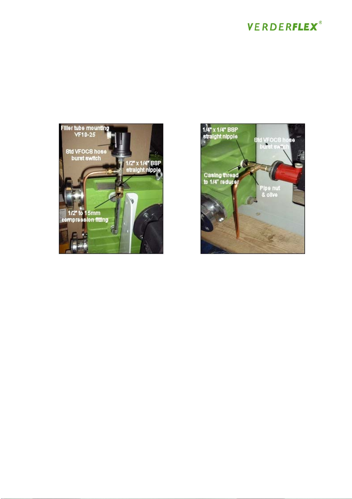
5. Accessories and Options
The VFOCS hose burst pressure switch can be mounted either onto the filler/breather tube or
direct to the back of the casing depending on the pump size (see Fig.23 below)
There is also the option to fit an add on vent kit which via a copper tube, allows the pump to
breath and reduce running temperature, but does not affect the signal to the switch during hose
burst
Figure 23
Fitting Instruction:
There are two types of installation, one is mounting to the filler/breather tube and affects the
VF10 to VF25 inclusive, as the switch body can interfere with the mounting frame. The other is
a direct mounting onto the rear case, which covers the rest of the pump range from VF32
upwards
Filler /Breather tube mounting:
Remove the plastic plug from the standard filler tube, then fit the brass compression fitting to the
filler tube using the pipe nut and collar and tighten the nut, so as to crimp the fitting onto the pipe
(tighten the nut until the fitting does not rotate and then a further ½ a turn, to avoid overtightening!)
This allows a ½” male to ¼” female reducer to be fitted which allows either the VFOCS pressure
switch or the optional tee piece and vent tube (see additional notes below) to be fitted first & then
the VFOCS switch to complete the assembly
Direct case mounting:
The ¼” bsp female reducer for the pump is simply fitted and this allows either the VFOCS
pressure switch or the optional tee piece and vent tube (see additional notes below) to be fitted
first & then the VFOCS switch to complete the assembly
48
Page 49

Vent Kit:
The kit is comprised of a ¼” BSP tee piece with a pipe nut / fitting and a copper vent tube. As
above after the ½” x ¼” BSP fitting is installed, this allows the tee piece to be fitted in a way
which allows the VFOCS switch to be fitted direct to it. This leaves an additional port to
accommodate the ¼” BSP pipe fitting, which once fitted will allow the vent tube to be secured by
a pipe nut and collar taking care not to over-tighten as above!
When fitting the pipe unions it is advisable to use PTFE tape to improve sealing, also two
wrenches must be used when tightening multiple fittings, this is important particularly when
tightening onto the filler/breather tube as it can strain & cause damage to the tube and its joints!
5.1 Accessories and Options
There are a number of accessories available to complement the VERDER hose pumps, all of
which are available through your local VERDER distributor:
Pulsation Dampener
A pulsing delivery is often common with hose pumps, which can lead to increased pipe losses or
heavy pulsation in the pipeline; pulsation is equally undesirable for the successful execution of
the process
A flexible bellow is installed and impinged on one side by compressed air or gas. Should
pulsation occur, the bellows increase their capacity and compress the air or gas. Hence the
peak pressure is not diverted into the pipeline or system, but is absorbed by the dampener.
There are three different types of dampener available:
• Manual adjustment dampener
• Automatically adjusted dampener
• Preset dampener (mostly used for high pressures where a normal air network would fail to
deliver sufficient pressure)
• Flexible Hose
Your VERDER distributor will be able to advise you further by referring to the separate sales
literature available. It should be noted that whilst pulsation dampers will reduce the size of the
pulse (typically by approx. 90%), they will therefore not totally eliminate pulsation.
Hygienic Hose Connections
A range of stainless steel connections is available to replace the port flange; fittings include a Tri
Clamp, RJT ; IDF and DIN 11851. In addition port flanges are available in stainless steel to suit
DIN, ANSI and JIS with stainless steel, polypropylene or PVDF inserts
Cleaning in Place
The specially developed VERDER Hygienic Pump offers full cleaning in place (CIP) and is ideal
for applications in the food industry, where the elimination of bacterial growth is essential - details
of this pump are available from your local VERDER distributor
Special Coatings
Pump components can be coated in a variety of specialist materials to offer higher levels of
chemical resistance or wear. Please ask your VERDER distributor for details on an individual
basis
49
Page 50
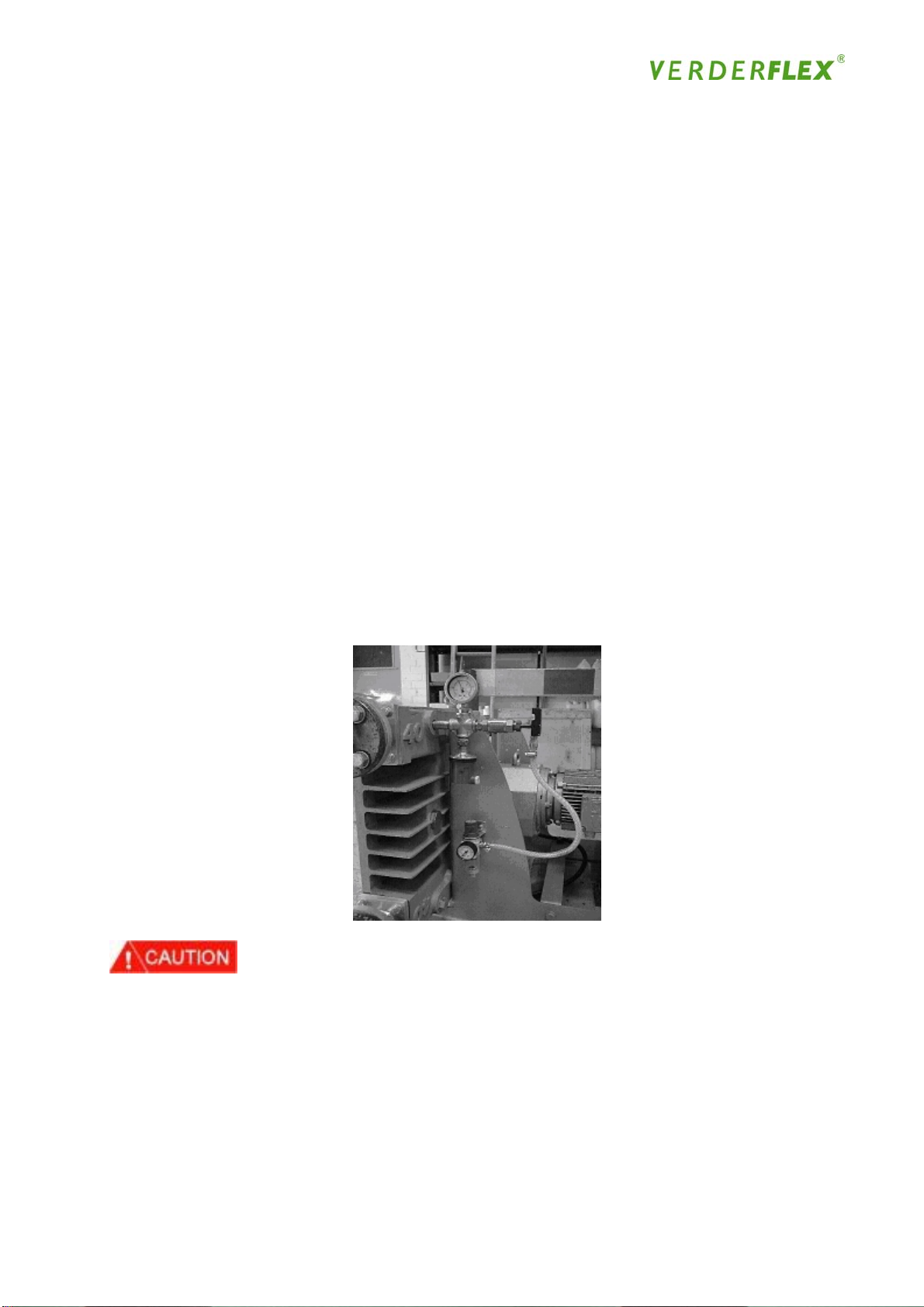
Hose Failure Detection
One of the VERDER’s many advantages is the exceptional lifetime of the hoses. Normal wear
does take its toll on the hose and in time it will need to be exchanged for a new one. Throughout
the hose’s lifetime, it is essential that any possible failure is noticed in sufficient time to prevent
leakage into and damage to the pump housing and unit. Loss of flow can also be monitored as
a pre-failure indicator.
To prevent this, VERDER has developed a capacitive sensor to be screwed into the fill pipe. If a
hose does rupture, the liquid leaking into the housing will cause the fluid level to rise. Where the
level in the filler tube reaches the height of the sensor, an alarm sounds and either the motor
shuts down or the valves close automatically
Vacuum Equipment
When pumping highly viscous liquids, it may be necessary to create a vacuum inside the pump
housing to help the hose to regain its natural round profile, assisting suction capabilities and
ensuring the maximum flow rate
VERDER recommends the installation of a vacuum assist system for the VF25 - VF80 using an
electric or a pneumatic air-driven vacuum pump. The installation consists of a small vacuum
pump mounted on the pump frame, which evacuates the pump housing - the lowest pressure of
the pump must match the suction pressure of the hose pump. It is advised that a lowest
pressure possible manometer be installed at the suction side
Figure 24
When the vacuum assist unit has been installed, pulsation can still occur as it has no impact on
pulsation. If this also influences the efficiency of the flow adversely, VERDER recommends the
installation of a pulsation dampener (see above)
50
Page 51
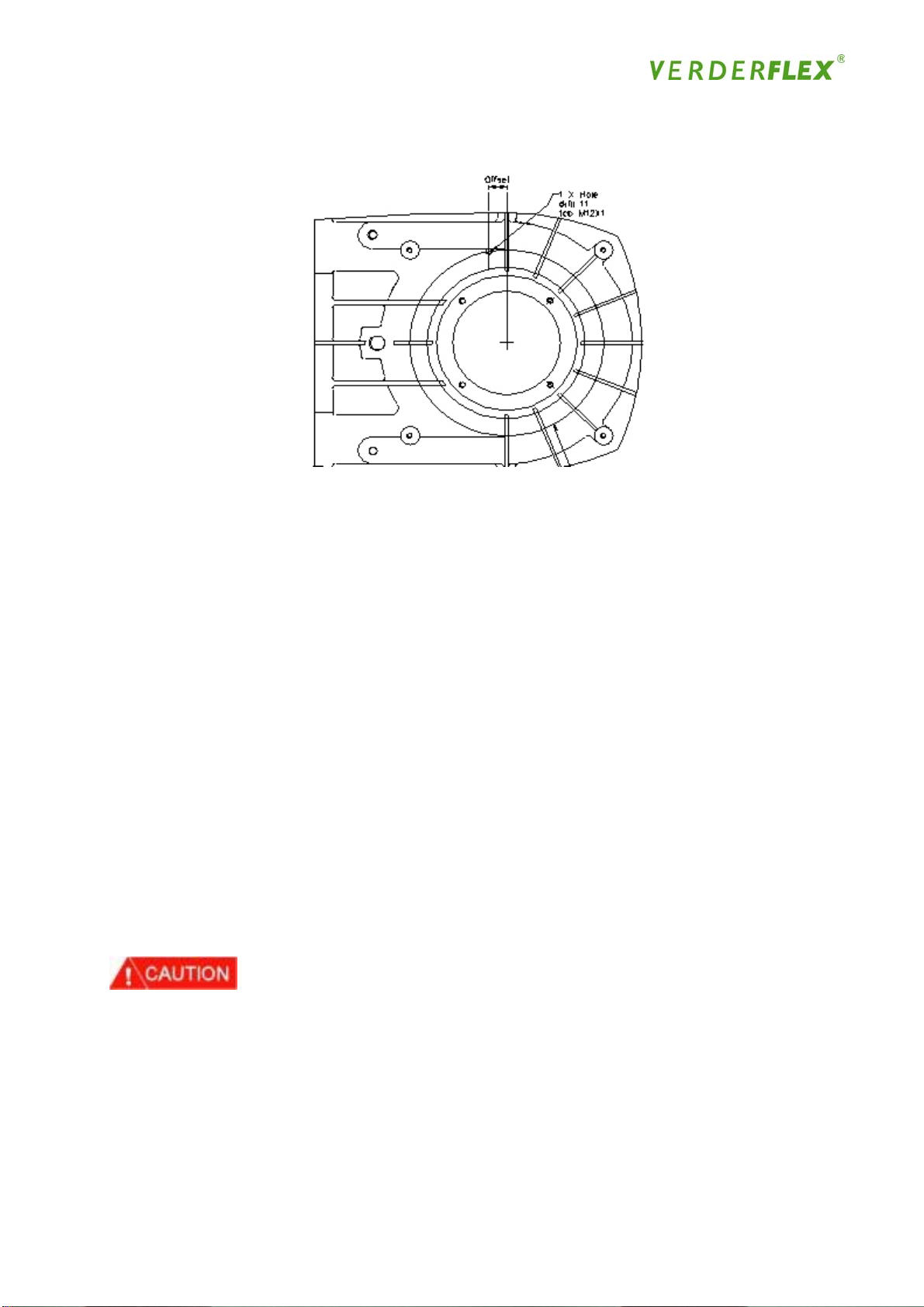
RPM Sensor
VERDER Sensor installation PCD’s
Pump Model Recommended PCD Offsets
VF10 Ø 110 (Front Cover) 14mm
VF15 Ø 195 (Rear Casing) 23mm
VF25 Ø 240 (Rear Casing) 27mm
VF32 Ø 300 (Rear Casing) 33mm
VF40 Ø 415 (Rear Casing) 41mm
VF50 Ø 537 (Rear Casing) 54mm
VF65 Ø 720 (Rear Casing) 48mm
VF80 Ø 850 (Rear Casing) 56mm
VF100 Ø 1000 (Rear Casing) 91mm
VF125 Ø 1230 (Rear Casing) 114mm
Note: Offset is related to the rib positions on the casing, but the front cover inspection window is
best utilized for the VF10 & VF15 where the cover should be tapped and locked from the outside
as there is no running clearance inside the pump! Siting of the hole must be at the top of the
pump in relation to its final installation position to avoid excess contact with the lubricant and its
contaminants during operation!
The rotor rim/central boss or shoe should be drilled and tapped to accommodate the interrupter,
which can typically be a small bolt for example. This should be used in the final sensor setting,
in respect of measuring the amount of protrusion required through the case/cover to sense the
bolt head during rotation, in line with the sensors pick up range.
On close-coupled pumps fitted with a vacuum unit, it may be necessary to fit a second or double
lip seal to the gear motor output shaft (to prevent the oil being sucked from the gear into the
pump housing) together with a retaining plate (to stop the lip seal being sucked out)
Future Developments
VERDER’s in-house team of engineers are continuously striving to develop the hose pump and
its application to new areas; naturally this covers the development of accessories and
complementary versions of the hose pump to achieve maximum efficiency and performance.
Feedback from operators and customers is always welcomed therefore, and any comments or
queries concerning your particular application should be forwarded to your local VERDER
distributor, who will then forward them to VERDER
51
Page 52

6. Risk Assessment & Preventative measures
Pump Build & Operational Safety:
6.1 Normal Operation Risk & Preventative Measures:
Normal Operation Foreseeable
Malfunction
Pressure too high in
casing
Blocked Pump
Pressure in tube
during its replacement
Tube rupture causing
hazardous medium to
spray out
Incorrect Assembly
Exceed recommended
temperatures
Polypropylene Insert
Use
Excessive noise Personal Injury N/A Observe safety
Product chemical
reaction
Drive Spec to pump
assembly
Tube rupture causing
hazardous medium to
spray out
Distortion at high
Operating
temperatures
Potentially Explosive
Check to ensure an
Rare Malfunction Preventative
Measures
Do not exceed the
maximum working
pressure of 16 bar.
Install a suitable safety
valve in the discharge
line in order to prevent
over-pressurization.
This must be in turn
checked on a regular
N/A
N/A Ensure lubricant
N/A Check operational
N/A Carry out product
basis. Do not work on
a running pump near
to filler tube /
inspection window.
When dismantling
pump isolate power
and relieve
Observe correct build
procedure as per
operator/build/
maint. manual.
level/shimming is
correct, also temp.
monitoring equipment
can be fitted to front
cover.
spec and use
alternative stainless
steel of PVDF
inserts
regulations governing
work in close proximity
& the wearing of
appropriate ear
protection
handling measures
during installation /
operation to ensure
operator safety.
explosion proof motor
is fitted to a flat pack
pump assembly if it is
to be used in an
explosive environment.
52
Page 53

Rotating Coupling Personal Injury N/A All flat packed long
coupled assemblies to
carry guarding advice
or have guards
installed during build.
Hazardous medium in
pump casing after tube
burst
Pump operational
safety precautions
Construction materials
not resistant to
pumped media
Verderlube Pump
lubricant not resistant
to pumped media
Personal Injury N/A Safety precautions to
be observed in the
form of isolating power
before dismantling.
Inspection window &
front cover, a special
tool is always required
to remove it.
Personal Injury N/A Always use eye &
hand protection during
pump dismantling
Adverse chemical
reaction, heat build up,
personal injury
Adverse chemical
reactions to glycerine
based products with
strong acids and
oxidising agents, with
risk of explosion
N/A Ensure sub
components
Other than hose is
compatible with media
being pumped
N/A Ensure Verderlube
lubricant is compatible
with media being
pumped, if not then
Verdersil MUST be
used!
6.2 Explosive Operation Risk & Preventative Measures:
Ignition Hazard Assessment
Normal
Operation
Bearings N/A All bearings are
Foreseeable
Malfunction
Bearing failure or
loss of lubrication
Rare
Malfunction
N/A The bearing
Prevention
measures
sealed for life or
greased. Drive
spec capability is
in excess of radial
loads applied
during pump
operation
housings need to
be examined for
signs of
overheating,
abnormal noise or
discolouration on
a daily basis.
Alternatively,
continuous temp.
monitoring can be
fitted and set to
trip the drive
power at 10k
above normal
running temp.
Ignition
Protection
Instruction
manual &
constructional
safety `c`
Instruction
manual or control
of ignition source
`b` if monitoring is
fitted
53
Page 54

Frictional heat of
moving parts
inside the
gearbox
Unacceptable
Guarding Mechanical
Dust deposits on
Static Discharge Hose Failure
Liquid transfer
Rubbing /
N/A The moving parts
N/A A level plug is
loss of oil from
gearbox
N/A Ensure secure
contact
N/A Guarding or
gearbox
through pump
outlets
cleaning of plastic
inspection
window
N/A
inside the
gearbox are
submersed in oil /
grease which acts
as a lubricant,
spark quenching
agent & coolant
provided on the
gearbox. The oil
level has to be
checked for low
level and signs of
contamination
and aligned
correctly, use
brass plate
regular cleaning
is needed to
prevent deposits
deeper than 5mm
accumulating
The hose inside
the casing is
covered and / or
submersed in oil
which acts as a
lubricant, spark
quenching agent
and coolant
Metal parts are
supplementary
bonded to provide
an electrically
conductive path
less 100 Ohm.
This also is
particular to pvdf
& polypropylene
inserts
Supplementary
bonding may be
required, also
clean in place
where possible
using non nylon
cloth.
Liquid immersion
`k`
Instruction
Manual
Non sparking +
Instruction
manual
Instruction
Manual
Liquid Immersion
`k`
National
standards for
electrostatic
requirements plus
user instruction
National stds for
electrostatic use+
manual.
Discharge of
component
before refit if
Removed for
cleaning.
54
Page 55

Static Discharge Overfilling &
discharge of
pump media
through filler tube
Pump operation
in an explosive
atmosphere
Frictional heat of
moving parts
inside the casing
Unacceptable
Front Cover High surface
Change in duty
by reduction of
rpm
H&S in an
explosive
environment
Risk of sparking
loss of lubricant
from casing
through leaks or
suction
temperature
OverTemp N/A Add forced fan
Earth clamp can
N/A
N/A
N/A
N/A As above plus
be fitted or an
optional level
sensor fitted.
Alternatively an
optional burst
pressure sensor
can be fitted both
of which shut
down the drive
motor.
Ensure during
pump operation a
warning triangle
with black letters
`Ex’ on a yellow
background is
displayed at
points on entry to
work area
The moving parts
inside the casing
are covered and /
or submersed in
oil which acts as
a lubricant, spark
quenching agent
and coolant
A level plug
is/can be
provided on the
front cover. The
oil level and
sealing joints
have to be
checked weekly.
Alternatively, a
low level sensor
can be fitted and
set BELOW
normal operating
level, taking into
account level
fluctuations.
ensure shimming
is correct and
pump does not
run dry for long
periods
cooling or
thermistors
Instruction
Manual
Control of ignition
source `b` if
second option
fitted
EN 13463-1
Liquid Immersion
`k`
Instruction
manual or control
of ignition source
`b` if monitoring is
fitted
Contact drive
manufacturer
To control ignition
source
55
Page 56

Optional Hose
burst pressure
sensor
Mechanical
coupling
Closed liquid
internal circuit
Closed valve
condition
Electrical Vac
Assist
Explosion risk
from spark
Mechanical
slippage /
breakage
Excess
temperature
Excess
temperature and
pressure
Explosion risk N/A Elect. Option has
N/A Current Huba 625
sensor must not
be used for
explosive
operation. An
alternative Exd /
EExd component
should be used
N/A Carry out routine
maintenance to
check for security
N/A Fit temp. probe to
front cover or
continuous temp.
monitoring can be
fitted and set to
trip the drive
power at 10k
above normal
running temp.
N/A Carry out routine
maintenance
checks to ensure
controlled temp &
gauge pressures
IP54 motor so an
air operated unit
is recommended,
ensure internal
spool valve on
Piab is of brass
construction
Instruction
manual plus
control of ignition
source `b` if
option used
Instruction
manual
Instruction
manual and
control of ignition
source `b` if
monitoring is
fitted
Instruction
manual
Instruction
manual plus
control of ignition
source `b` if non
sparking option is
used.
Glossary of terms:
Safety `c` - refers to the integral from standard constructional design
Ignition source `b`- refers to protection incorporated to control an ignition source
Liquid Immersion `K` - refers to protection of ignition due to use of spark quenching agent
Eexd / Exd – refers to explosion proof electrical components with flameproof protection
EN 13463-1 - European norm standards for Non Electrical equipment in explosive atmospheres
56
Page 57
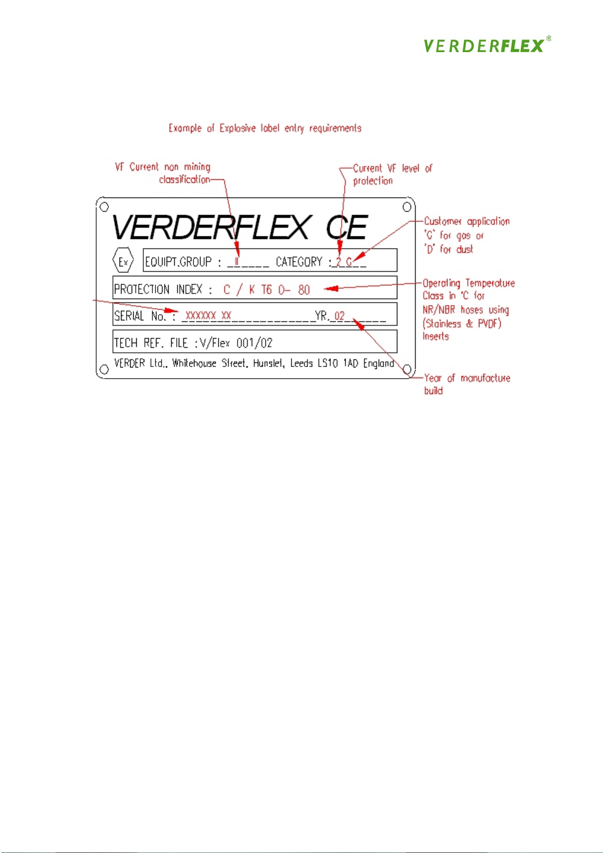
6.3 Explosion Proof Labelling:
Note: This label is only fitted onto pumps supplied as Atex compliant at time of order
Note: As operating temperature is governed by type of hose and insert used, here are some
other examples of temperature indication:
T5 (0 – 100) - (EPDM Hose with Stainless / PVDF Inserts)
T6 (0 – 40) - (Any Hose fitted with Polypropylene Inserts)
Note: Future development to overcome higher protection requirements and the event of rare
malfunctions may allow the product to be marketed to Equipment group II category 1,this will
form a sound basis for further/future categorizing to cater for the mining industry.
Therefore guidelines are according to current initial specification and as such may be subject to
amendment.
6.4 Pump & Hose: Storage during Plant shutdowns / on site storage
1. Introduction
VERDERFLEX pumps are designed for continuous use, however, there may be instances when
pumps are withdrawn from use and stored for periods of more than 2 weeks. We recommend
certain pre-storage actions and precautions be taken whilst pumps and their components are not
in use. Similarly, hoses and lubricants may be held as stock to service working pumps and their
recommended storage conditions are advised.
57
Page 58

2 Pre-Storage Actions
• The hose should be removed from the pump and the lubricant drained out of the pump
casing.
• The pump casing should be washed out and allowed to dry and any external build up of
product removed.
• The gearbox should be drained and re-filled with oil in accordance with the manufacturers
recommendations.
3 Storage Conditions
• Pumps should be stored in a dry environment. Depending on these conditions, it may be
advisable to place a moisture-absorbing product, such as Silica gel, inside the pump’s casing
or to coat the pump’s inner surfaces with moisture-repelling oil, whilst the pump is stored.
• Gearboxes may require intermittent attention (such as periodic rotation) as indicated by the
gearbox manufacturer’s recommendations.
• Hoses should be stored as supplied in their wrapper and should be stored away from direct
sunlight and at room temperature.
• Lubricants should be stored under normal warehouse conditions with their caps securely
fastened.
• It is recommended that lubricant containers be inverted every month and shaken before use
in pump!
4 Shelf Life
Item Recommended Shelf Life
Pump assembly No shelf life providing pump stored in a dry
atmosphere
Natural Rubber (NR), Nitrile Buna Rubber (NBR)
and Hypalon (CSM) hoses
EPDM hoses 3 years from date of supply
VERDERLUBE Lubricant 1 year from date of supply
VERDERSIL Lubricant 3 years from date of supply
Gearbox and Motor In accordance with manufacturer’s
18 months from date of supply
recommendations
For further information, please contact your local VERDERFLEX distributor or contact the
VERDERFLEX team directly on [email protected]
58
Page 59

6.5 Other Information:
Warranty Registration
Your VERDER distributor will have completed a warranty card on your behalf, which is returned
to VERDER for registration on VERDER’s warranty scheme. Please ensure that the distributor
has the following details from your initial and any subsequent orders for pump(s) and / or spares:
• pump / spares make and type
• serial number
• application
• media to be pumped
• pressure
• temperature
• capacity
• suction
• motor size
• date of order and delivery
• VERDER reference
Full completion of this card is essential for you to be covered by VERDER’s outstanding warranty
schemes. Please be aware of the declaration that you undertake to use only VERDER spare
parts - this is an essential part of the warranty scheme and is legally binding. The card will also
act as a record of your dealings with VERDER
This information will similarly be required if and when you should need to order spare parts from
your local VERDER distributor
Should you have cause to return the pump for any reason, please ensure that you inform the
local distributor as fully as possible of the details of the problem; the distributor has the necessary
documentation for completion of the warranty application to VERDER and is aware that this has
to be completed in full before VERDER can examine the application
Complaints Procedure
VERDER takes its responsibilities to its customers extremely seriously and prides itself on its
comprehensive complaint procedures. Should you be dissatisfied with your VERDER pump(s) or
with any aspect of the service you have received, then please contact your local VERDER
distributor in the first instance to discuss the matter fully
The distributor will then take the matter up with VERDER, acknowledging his actions to the
customer and indicating a time scale by which he will reply. You will receive a response from the
distributor with VERDER’s initial comments and proposed plan of any further action. If you feel
that your complaint has still not been resolved satisfactorily, you should contact VERDER Ltd
directly at the address given at the end of this chapter
VERDER Group Literature
VERDER supplies its range of Group literature and product documentation in a number of
languages and variety of software packages - please advise your VERDER distributor if you are
interested in receiving other information on VERDER, indicating in which languages / format
59
Page 60

VERDER and its distributors undertake to conduct all its dealings with you as comprehensively,
courteously and promptly as possible. Customer care is one of VERDER’s top priorities
Distributor Contact Details:
VERDER Contact Details
VERDER Ltd
Whitehouse Street
Leeds LS10 1AD
ENGLAND, UK
Tel: (+44) 113 222 0279
Fax: (+44) 113 222 0291
Email: [email protected]
60
Page 61

Appendix A - Verderlube Safety Data Sheet
Used lubricant may become contaminated with pumped product, also verify precautions and advice
against relevant product information
1 Identification of the Substance/Preparation and of the Company/Undertaking
1.1 Identification of Substance or Preparation
PRODUCT NAME Verderlube®
CHEMICAL IDENTIFICATION Glycerine based blend
CAS NUMBER Preparation
USE Food Grade - Pump Lubricant / Coolant
1.2 Company Identification
PRODUCER / SUPPLIER VERDER LIMITED
WHITEHOUSE STREET
HUNSLET
LEEDS LS10 1AD
GREAT BRITAIN
TEL NUMBER +44 (0) 113 222 0250
FAX NUMBER +44 (0) 113 246 5649
EMERGENCY TEL NUMBER
For advice on this product call: +44 (0) 113 222 0250
2 Composition / Information o n Ingredients
This product contains no substances classified as hazardous to health in concentrations that
•
should be taken into account according to EC directive 91/155/EC
• Main constituent may cause irritation to eyes and skin.
• Irritating to respiratory system in the form of a mist.
61
Page 62

3 Hazardous Identification
This product is not classified as hazardous according to EC directive 91/155/EC
• May cause irritation to eyes and skin.
• Irritating to respiratory system in the form of a mist.
• Contact with hot product may cause burns.
• Product is a lubricant and in the event of untreated spillage, can cause external surfaces to
become slippery when wet
4 First Aid Measures
Used lubricant may become contaminated with pumped product, also verify precautions and
advice against relevant product information
4.1 Ingestion
• Give 500 ml of Water to drink
• DO NOT INDUCE VOMITING!
• Except as a deliberate act, the ingestion of large amounts of product is unlikely. If this should
occur, do not; induce vomiting, obtain medical advice.
4.2 Inhalation
• If inhalation of fumes from overheated material causes irritation to the nose or throat, or
coughing, remove to fresh air. Obtain medical advice if any symptoms persist.
4.3 Skin Contact
Wash thoroughly with mild soap and water as soon as reasonably practical.
•
• Remove heavily contaminated clothing and wash underlying skin
4.4 Eye Contact
• Wash eye thoroughly with copious amounts of water, ensuring eyelids are held open.
• Obtain medical advice if any pain or redness develops or persists.
5 Fire Fighting Measures
Used lubricant may become contaminated with pumped product, also verify precautions and
advice against relevant product information
5.1 Extinguishing Media
• Alcohol resistant foam, dry powder or water fog
62
Page 63

5.2 Extinguishing Media To Avoid
• Do not use water jets
5.3 Unusual Fire and Explosion Hazards
• Avoid spraying directly into storage containers because of danger of boil over
5.4 Special Protective Equipment for Fire fighters
• Protective clothing and approved breathing apparatus when in close proximity of fire
During burning, poisonous acrolein may be found
•
6 Accidental Release Measures
Used lubricant may become contaminated with pumped product, also verify precautions and
advice against relevant appropriate product information
6.1 Personal Protection
• Wear goggles and gloves. If spillage has occurred in a confined space, ensure sufficient
ventilation and check that a safe, breathable atmosphere is present before entry.
6.2 Environmental Precautions
• Protect drains from spills and prevent entry of product. Treated effluent may be biodegradable.
Recover cleaning water for later treatment.
6.3 Methods for Cleaning Up
• Contain and recover liquid, soak up with absorbent material (sand, peat, etc.) or contain and
shovel into drums or containers. Remove residue by spraying with water
7 Handling and Storage
Used lubricant may become contaminated with pumped product, also verify precautions and
advice against relevant product information
7.1 Handling
• Contact with hot product causes burns.
Avoid contact with eyes. If splashing is likely to occur wear a full visor or chemical goggles to
•
appropriate local national standards.
• Avoid frequent or prolonged skin contact with fresh or used product.
• Wash hands thoroughly after use.
63
Page 64

7.2 Storage
• Store under cover away from moisture and sources of ignition. Do not overheat in storage.
The lubricant/coolant is hygroscopic; keep the container tightly closed
•
8 Exposure Controls / Personal Protection
Used lubricant may become contaminated with pumped product, also verify precautions and
advice against relevant product information
8.1 Personal Protection
• Hand Protection PVC or Rubber Gloves
• Eye Protection Chemical goggles
• Respiratory Protection Respiratory protection is unnecessary, providing concentration of
vapour, mists or fumes is adequately controlled.
8.2 Occupational Exposure Limits
• Ensure good ventilation.
• Threshold limit Not tested
9 Physical and Chemical Properties
FORM Viscous liquid
COLOUR Blue. Colourless may be supplied to special order
ODOUR Odourless
SOLIDIFICATION POINT -40°C / -40°F approx.
FLASH POINT 177°C / 350°F approx. (COC: ISO 2592)
BOILING POINT 290°C / 554°F
SOLUBILITY IN WATER Miscible (at 20°C)
VAPOUR PRESSURE
VISCOCITY 700 mPaS approx. @ 20°C / 68°F
pH 7 approx.
AUTO IGNITION TEMPERATURE 400°C / 750°F approx.
EXPLOSION LIMITS Not established
DENSITY (20°C/68°F) 1245 kg/m3 approx.
BEHAVIOUR WITH WATER AT 20°C Hygroscopic
(20°C / 68°F) <0.01 mbar
(100°C / 210°F) <1mbar
64
Page 65

10 Stability and Reactivity
Used lubricant may become contaminated with pumped product, also verify precautions and
advice against relevant product information
10.1 Conditions to Avoid
• Preparation is stable and unlikely to react in a hazardous manner under normal conditions of
use.
• No special precautions other than good housekeeping of chemicals.
• Hazardous polymerisation reactions are unlikely to occur.
• This material is combustible.
10.2 Materials to Avoid
• Avoid contact with strong oxidizing agents, nitrogenous compounds and strong acids: risk of
violent and or explosive reactions with pure compounds.
10.3 Hazardous Decomposition Products
• During burning, poisonous acrolein may be found – very toxic by inhalation.
• Incomplete combustion / thermal decomposition will generate smoke, carbon dioxide and
hazardous gases, including carbon monoxide.
11 Toxicological Information
Used lubricant may become contaminated with pumped product, also verify precautions and
advice against relevant product information
11.1 Toxicity Data
• General purpose food grade lubricant /coolant
LD
•
oral (rat) 12600 mg/kg (not harmful) *
50
11.2 Significant Data with Possible Relevance to Human Health
Eyes - Unlikely to cause more than transient stinging or redness if accidental eye contact occurs
•
• Skin - Unlikely to cause harm to the skin
• Ingestion - Unlikely to cause harm if accidentally swallowed in small doses, although larger
quantities should be avoided
• Inhalation - At ambient temperatures this product will be unlikely to present an inhalation
hazard
65
Page 66

12 Ecological Information
Used lubricant may become contaminated with pumped product, also verify precautions and
advice against relevant product information
12.1 Mobility
• Spillage may penetrate the soil; unused preparation is food grade and is inherently harmless.
12.2 Persistence and Degradability
• This preparation is inherently biodegradable.
12.3 Bio Accumulative Potential
• There is no evidence to suggest that bioaccumulation will occur.
12.4 Aquatic Toxicity
• Verderlube is miscible in water. It is not considered harmful in low concentrations.
Water pollution reactors gO
5
BOD
: 0,87 (NEN 3235-5.4)
1
BOD
: 1.16 (NEN 3235-5.3)
Fish: goldfish LC50 (24h):>5000 mg/1 (modified ASTM D1345)
• The aquatic toxicity (TLm
) is >1000mg/1, which is defined by NIOSH as an insignificant hazard
96
/g
2
13 Disposal Considerations
Used lubricant may become contaminated with pumped product, also verify precautions and
advice against relevant product information
13.1 Waste Disposal Method(s)
• Where possible, arrange for unused product to be recycled.
• Disposal of preparation should be via an authorized person/licensed waste disposal contractor in
accordance with local regulations.
• Incineration may be carried out under controlled conditions provided that local regulations are
met.
• Dispose of preparation and container carefully and responsibly. Do not dispose of preparation
near ponds, ditches, down drains onto soil.
14 Transport Information
• Not classified as dangerous for transport (RID/ADR-ADNE-IATA-IMDG-MARPOL-ICAO)
15 Regulatory Information
66
Page 67

Classification - Classification not required
•
16 Other Information
• Employees of the Verder group have not experienced any harmful effect during normal handling
and production.
• Verderlube
*The information contained in this sheet is based on our knowledge of the preparation at its delivery
date and that the information contained herein is current as of the date of this data sheet. Since the
use of this information, and of these opinions and the conditions of use of this preparation is not
within the control of Verder Limited, it is the user’s obligation to determine the conditions of safe use
of the preparation.
The information contained in this sheet is based on our knowledge of the product at its delivery date
®
and Verderflex® are registered trademarks.
67
Page 68

Appendix B - Verdersil Safety Data Sheet
Verdersil is the lubricant / coolant used with the Verderflex® range of and other peristaltic or hose
pumps
Used lubricant may become contaminated with pumped product, also verify precautions and advice
against relevant product information
1 Identification of the Substance/Preparation and of the Company/Undertaking
1.1 Identification of Substance or Preparation
PRODUCT NAME Verdersil
CHEMICAL IDENTIFICATION Silicone fluid (Polydimethyl siloxane 350 CPS)
CAS NUMBER Preparation
USE Pump Lubricant / Coolant
1.2 Company Identification
PRODUCER / SUPPLIER VERDER LIMITED
WHITEHOUSE STREET
HUNSLET
LEEDS LS10 1AD
GREAT BRITAIN
TEL NUMBER +44 (0) 113 222 0250
FAX NUMBER +44 (0) 113 246 5649
EMERGENCY TEL NUMBER
For advice on this product call: +44 (0) 113 222 0250
2 Composition / Information o n Ingredients
This product, Polydimethyl siloxane, contains no substances classified as hazardous to health in
•
concentrations that should be taken into account according to EC directive 91/155/EC
• Main constituent may cause irritation to eyes and skin.
• Irritating to respiratory system in the form of a mist.
68
Page 69

3 Hazardous Identification
This product is not classified as hazardous according to EC directive 91/155/EC
• May cause irritation to eyes and skin.
• Irritating to respiratory system in the form of a mist.
• Contact with hot product may cause burns.
• Product is a lubricant and in the event of untreated spillage, can cause external surfaces to
become slippery when wet
4 First Aid Measures
Used lubricant may become contaminated with pumped product, also verify precautions and advice
against relevant product information
4.1 Ingestion
• No first aid should be required but should any symptoms persist, seek medical advice
4.2 Inhalation
• No first aid should be required but should any symptoms persist, seek medical advice
4.3 Skin Contact
• No first aid should be required but should any symptoms persist, seek medical advice
• Wash thoroughly with mild soap and water as soon as reasonably practical.
• Remove heavily contaminated clothing and wash underlying skin
4.4 Eye Contact
Direct contact may cause temporary redness and discomfort
•
• Wash eyes thoroughly with copious amounts of water for at least 10 minutes, ensuring that
eyelids are held open
• Obtain medical advice if any pain or redness develops or persists
5 Fire Fighting Measures
Used lubricant may become contaminated with pumped product, also verify precautions and advice
against relevant product information
5.1 Extinguishing Media
• Carbon dioxide, foam, dry powder or water spray
• Water can be used to cool fire-exposed containers
69
Page 70

5.2 Extinguishing Media To Avoid
• None known
5.3 Unusual Fire and Explosion Hazards
• None known
5.4 Special Protective Equipment for Fire fighters
• A self-contained respirator and protective clothing should be worn. Keep containers cool with
water spray until well after the fire is out. Determine the need to evacuate or isolate any area in
accordance with local emergency plans.
• Hazardous combustion products include Silica, Carbon Oxides and traces of incompletely
burned carbon compounds may form. Formaldehyde may also be found
5.5 NFPA Profile
• Health: 0 Flammability: 1 Instability/Reactivity: 0
Note: NFPA = National Fire Protection Association
6 Accidental Release Measures
Used lubricant may become contaminated with pumped product, also verify precautions and advice
against relevant appropriate product information
6.1 Personal Protection
• Wear goggles and gloves. If spillage has occurred in a confined space, ensure sufficient
ventilation and check that a safe, breathable atmosphere is present before entry.
6.2 Environmental Precautions
• Prevent from spreading or entering drains, ditches or rivers by using sand, earth or other
appropriate barriers
6.3 Methods for Cleaning Up
• Determine the need to evacuate or isolate the area in accordance with local emergency plan.
Very large spills should be contained by bunding or similar methods. Contain and recover
liquid, soak up with absorbent material (sand, peat, etc.) or contain and shovel into drums or
containers.
Small spillages may be washed to drains with detergent and water.
•
• Caution : Spilled product will produce an extremely slippery surface
70
Page 71

7 Handling and Storage
Used lubricant may become contaminated with pumped product, also verify precautions and advice
against relevant product information
7.1 Handling
• Contact with hot product causes burns.
• Avoid contact with eyes. If splashing is likely to occur wear a full visor or chemical goggles to
appropriate local national standards.
• Avoid frequent or prolonged skin contact with fresh or used product.
• Wash hands thoroughly after use.
7.2 Storage
• Store under cover away from moisture and sources of ignition. Do not overheat in storage.
8 Exposure Controls / Personal Protection
Used lubricant may become contaminated with pumped product, also verify precautions and advice
against relevant product information
None of the components have assigned exposure limits
8.1 Personal Protection
Hand Protection PVC or Rubber Gloves
•
• Eye Protection Safety glasses should be worn
• Respiratory Protection Respiratory protection is unnecessary, providing concentration of
vapour, mists or fumes is adequately controlled.
8.2 Occupational Exposure Limits
• Ensure good ventilation.
No known assigned exposure limits
•
8.3 Additional Information
These precautions are for room temperature handling
Use at elevated temperatures may require additional precautions
71
Page 72

9 Physical and Chemical Properties
FORM Viscous liquid
COLOUR Colourless
ODOUR Odourless
SOLIDIFICATION POINT
< -45°C / <-60°F approx.
FLASH POINT 121°C / 250°F approx. (Closed cup)
BOILING POINT >200°C / >390°F
SOLUBILITY IN WATER 0 g/litre at 20°C
VISCOCITY 350 mPas approx. at 20°C / 68°F
AUTO IGNITION TEMPERATURE >200°C / >390°F.
EXPLOSION LIMITS Not explosive
DENSITY (20°C/68°F) 970 kg/m3 approx.
10 Stability and Reactivity
Used lubricant may become contaminated with pumped product, also verify precautions and advice
against relevant product information
10.1 Conditions to Avoid
Preparation is stable and unlikely to react in a hazardous manner under normal conditions of
•
use.
• No special precautions other than good housekeeping of chemicals.
10.2 Materials to Avoid
• Can react with strong oxidizing agents
10.3 Hazardous Decomposition Products
• Hazardous decomposition products including Formaldehyde and Silica can be formed, refer to
Toxicology Information, section 11.
11 Toxicological Information
Used lubricant may become contaminated with pumped product, also verify precautions and advice
against relevant product information
11.1 Toxicity Data
• General non-toxic lubricant /coolant
• Other than temporary discomfort on contact with the eyes, no adverse effects are normally
expected
72
Page 73

11.2 Significant Data with Possible Relevance to Human Health
• Eyes - Unlikely to cause more than transient stinging or redness if accidental eye contact
occurs
Skin - Unlikely to cause harm to the skin
•
• Ingestion - Unlikely to cause harm if accidentally swallowed in small doses, although larger
quantities should be avoided
• Inhalation - At ambient temperatures this product will be unlikely to present an inhalation
hazard
11.3 Other Health Hazard Information
• Product may emit Formaldehyde vapours at temperatures above 150°C/302°F in the presence of
air. Formaldehyde vapour is harmful by inhalation and irritating to the eyes and respiratory
system at breathing concentrations of less than 1ppm (1 part per million)
12 Ecological Information
Used lubricant may become contaminated with pumped product, also verify precautions and advice
against relevant product information
12.1 Environmental Fate and Distribution
• Air: This product is a high molecular weight liquid polymer, which has a very low vapour
pressure (<1mm Hg). As a result it is unlikely to become an atmospheric contaminant unless
generated as an aerosol
• Water: This product has a very low water solubility (< 100 ppb). As it has a specific gravity of <
1, if discharged to water, it will initially form a surface film. As the product is non-volatile and has
a high binding affinity for particulate matter, it will adsorb to particulates and sediment out.
• Soil: If discharged to surface water, this product will bind to sediment. If discharged in effluent to
a waste water treatment plant, the product is removed from the aqueous phase by binding to
sewage sludge. If the sewage sludge is subsequently spread on soil, the silicone product is
expected to degrade.
• Degradation: This product, polydimethylsiloxane, degrades in soil abiotically to form smaller
molecules. These in turn are either biodegraded in soil or volatilized into the air where they are
broken down in the presence of sunlight. Under appropriate conditions, the ultimate degradation
products are inorganic silica, carbon dioxide and water vapour. Due to the very low water
solubility of this product, standard OECD protocols for ready and inherent biodegradability are
not suitable for measuring the biodegradability of this product. The product is removed >80%
during the sewage treatment process.
73
Page 74

12.2 Environmental Effects
• Toxicity to Water Organisms: Based on analogy to similar materials this product is expected
to exhibit low toxicity to aquatic organisms.
• Toxicity to Soil Organisms: Experiments show that when sewage sludge containing
polydimethylsiloxane is added to soil, it has no effect on soil micro-organisms, earthworms or
subsequent crops grown in the soil.
12.3 Bioaccumulative
• This product is a liquid and is a high molecular weight polymer. Due to its physical size it is unable to pass
through, or be absorbed by biological membranes. This has been confirmed by testing or analogy with
similar products.
12.4 Fate and Effects in Waste Water Treatment Plants
This product or similar products has been shown to be non-toxic to sewage sludge bacteria.
•
Ecotoxicity Classification Criteria
Hazard Parameters
(LC50 or EC50)
Acute Aquatic
Toxicity (mg/L)
Acute Terrestrial
Toxicity
This table is adapted from "Environment a l Toxico l og y and Risk Asse s sm ent", ASTM STP 117 9, p.34 , 19 93 .
This table can be used to cl assify the ecotoxicity of this product when ecotoxicity data is listed above. Please read the
other information presented in the section concerning the overall ecological safety of this material.
High Medium Low
<=1 >1 and <=100 >100
<=100 >100 and <= 2000 >2000
13 Disposal Considerations
Used lubricant may become contaminated with pumped product, also verify precautions and advice
against relevant product information
13.1 Waste Disposal Method(s)
• Where possible, arrange for unused product to be recycled.
RCSA Hazard Class (40 CFR 261)
• When a decision is made to discard this material, as received, is it classified as a hazardous
waste? – No
• State or local laws may impose additional regulatory requirements regarding disposal
74
Page 75

14 Transport Information
• Not classified as dangerous for transport (RID/ADR-ADNE-IATA-IMDG-MARPOL-ICAO)
• DOT Road Shipment Information (49 CFR 172.101) – Not subject to DOT
15 Regulatory Information
• Labelling according to EEC Directive – No special packaging or labelling requirements
National legislation/regulations Ozone depleting chemicals – No ozone depleting chemicals are
present or used in manufacture
Status
EINECS: All ingredients listed or exempt
TSCA: All chemical substances in this material are included on or exempted from listing on the
TSCA Inventory of Chemical substances.
16 OSHA Hazard Regulatory Information to Standard CFR29 1910.1200
Contents of this MSDS comply with the OSHA Hazard Communication Standard 29 CFR
1910.1200.
TSCA Status: All chemical substances in this material are included on or exempted from listing on
the TSCA Inventory of Chemical Substances.
16.1 TSCA Status
All chemical substances in this material are included on or exempted from listing on the TSCA
16.2 EPA SARA Title III Chemical Listings
Section 302 Extremely Hazardous Substances: None.
Section 304 CERCLA Hazardous Substances:
Section 312 Hazard Class:
Acute: No
Chronic No
Fire No
Pressure No
Reactive No
Section 313 Toxic Chemicals
None.
None present or none present in regulated
quantities
75
Page 76

16.3 Supplemental State Compliance Information for California
•
Warning:
Drinking Water and Toxic Enforcement Act of 1986 (Proposition 65) as being known to cause cancer, birth
defects or other reproductive harm
- None known.
This product contains the following chemical(s) listed by the State of California under the Safe
16.4 Supplemental State Compliance Informati on for Massachusetts
No ingredient regulated by MA Right-to-Know Law present.
16.5 Supplemental State Compliance Information for New Jersey
CAS Number Wt % Component Name
63148-62-9 > 60.0 Polydimethylsiloxane
16.6 Supplemental State Compliance Information for Pennsylvania
CAS Number Wt % Component Name
63148-62-9 > 60.0 Polydimethylsiloxane
17 Other Information
• Employees of the Verder group have not experienced any harmful effect during normal handling
and production.
®
• Verdersil and Verderflex
are registered trademarks.
*The information contained in this sheet is based on our knowledge of the preparation at its delivery
date and that the information contained herein is current as of the date of this data sheet. Since the
use of this information, and of these opinions and the conditions of use of this preparation is not
within the control of Verder Limited, it is the user’s obligation to determine the conditions of safe use
of the preparation.
The information contained in this sheet is based on our knowledge of the product at its delivery date
76
Page 77
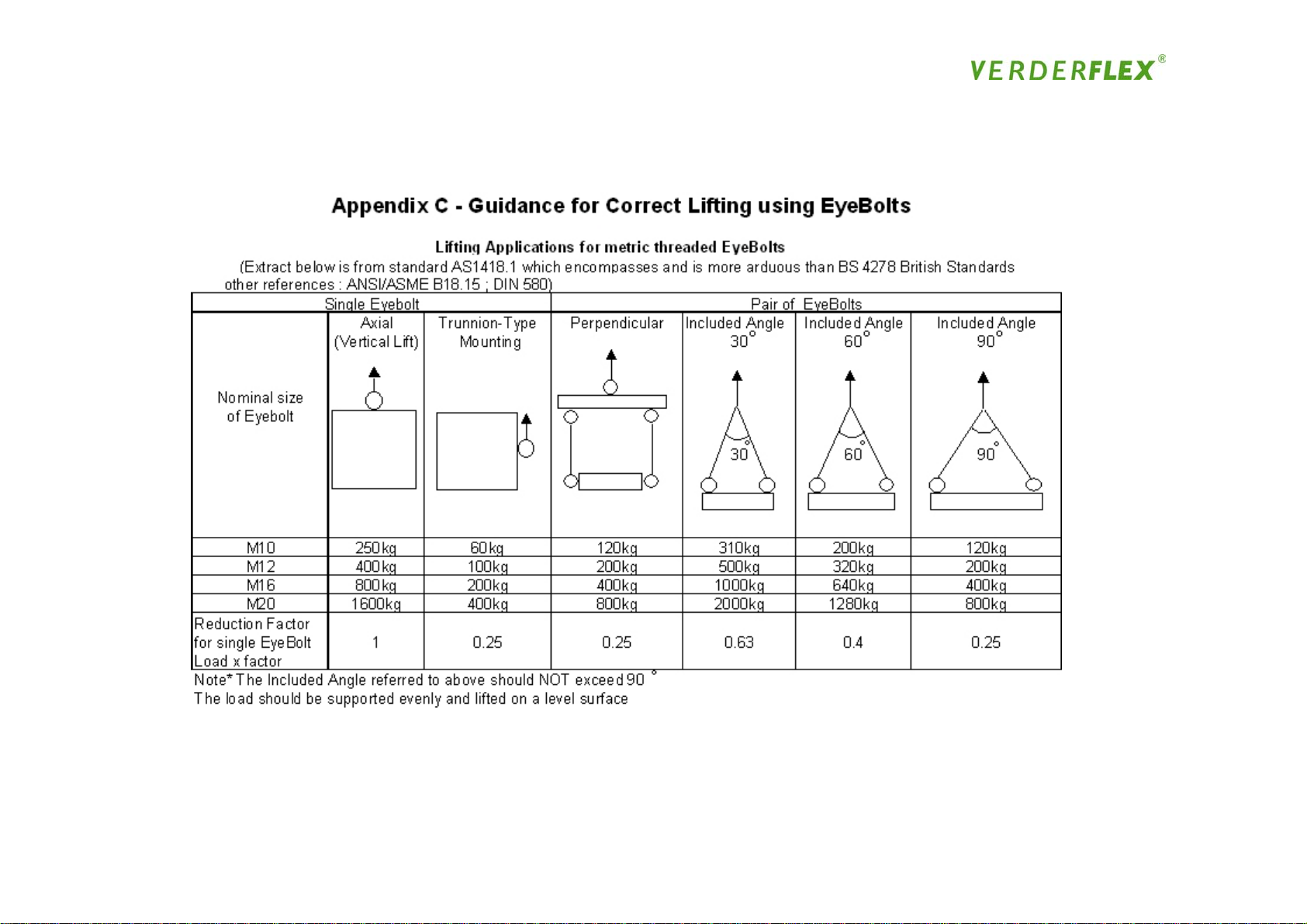
Appendix C
77
Page 78

VERDERFLEX Black NBR Food Grade hoses are suitable for conveying oily and
fatty foods in peristaltic pumps
Operating Protocol for
Verderflex Black NBR Food Grade Hose
Cleaning Protocol
VERDERFLEX Black NBR food grade hoses should be cleaned with the following protocol –
First flush 2% Nitric Acid (HNO3) solution for up to 3 minutes at up to 50°C
Second flush 2% Caustic soda (NaOH) solution for up to 20 minutes at up to 100°C
or 5% Caustic soda (NaOH) solution for up to 5 minutes at up to 100°C
or 20% Caustic soda (NaOH) solution for up to 20 minutes at ambient
Final flush Flush with clean water to remove all traces of cleaning solutions
Under no circumstances should VERDERFLEX Black NBR food grade hoses be cleaned with Sodium
Hypochlorite (NaOCl) based cleaning solutions or the above concentrations, exposure durations or
temperatures be exceeded.
EHEDG Approval
VERDERFLEX Black NBR food grade hoses can be used with suitably specified VERDERFLEX pumps to form
an EHEDG accredited hygienic pumping system. To comply with this certification both the approved
particle velocity must be maintained during the cleaning cycle and the appropriate hygienic port flanges
fitted. Should a pump to this specification be required, it should be agreed with your local VERDERFLEX
distributor before the pump is supplied.
Food Grade Approval
All VERDERFLEX Black NBR food grade hoses’ inner liners are certified as compliant to FDA –
CFR 21 Parts 170 to 189 – Item 177.2600
Hose Description
All VERDERFLEX Black NBR Food Grade hoses consist of a smooth black inner food grade liner
bonded to a non-food grade outer. The inner liner is a taste-free and odour-less.
Page 79

Verder Ltd
Whitehouse Street, Hunslet, Leeds LS10 1AD • Tel.: +44(0)113 222 0250 • Fax: +44(0)113 222 0291 • info@verderflex.com
AT
Wien • BE Aartselaar • CN Shanghai • CZ Praha • DE Haan • FR Eragny s/Oise • GB Leeds • HU Budapest
JP Tokyo • NL Groningen/Vleuten • PL Katowice • RO Bucuresti • SA Kya Sand • SK Bratislava • US Newtown
10-04-07-UK Rev.02
Pump Size Part Number
VF10 129.2021
VF15 129.2022
VF25 129.2023
VF32 129.2024
VF40 129.2025
VF50 129.2026
VF65 129.2027
VF80 129.2028
VERDERFLEX BLACK NBR FOOD GRADE HOSE PART NUMBERS
VERDERLUBE
The associated VERDERLUBE lubricant is also a food-grade product and is made from foodgrade
constituents. A separate product datasheet is available on request.
VERDERFLEX pumps using VERDERFLEX Black NBR Food Grade hoses must be installed in accordance
with recommendations made by the pump’s supplier. In particular, special care must be given to the suction
and discharge line conditions and that the hose is shimmed in accordance with VERDERFLEX’s
recommendations. Should there be any doubt about any installation details, these must be discussed with
the pumps’ supplier.
Particle Release
All hoses will release small quantities of rubber into the product stream, especially immediately after the
hose installation and just prior to hose failure. Whilst the rubber released will be food grade particles,
these may cause end-user concerns about contamination and so we recommend suitable particle capturing
devices such as filters are fitted into the pump’s discharge line.
Hose Installation
All VERDERFLEX Black NBR Food Grade hoses must be installed in accordance with the
procedures defined in the VERDERFLEX Safety, Operating and Maintenance manual.
Identification
VERDERFLEX Black NBR Food Grade hoses can be identified by:
a) Both an external Yellow Coding / Identification tape and an additional white
longitudinal stripe
b) On supply as a spare part, they will have their ends sealed with Aluminium foil
Pump Installation
www.verderflex.com�
Page 80

Page 81

75
 Loading...