

Page 1
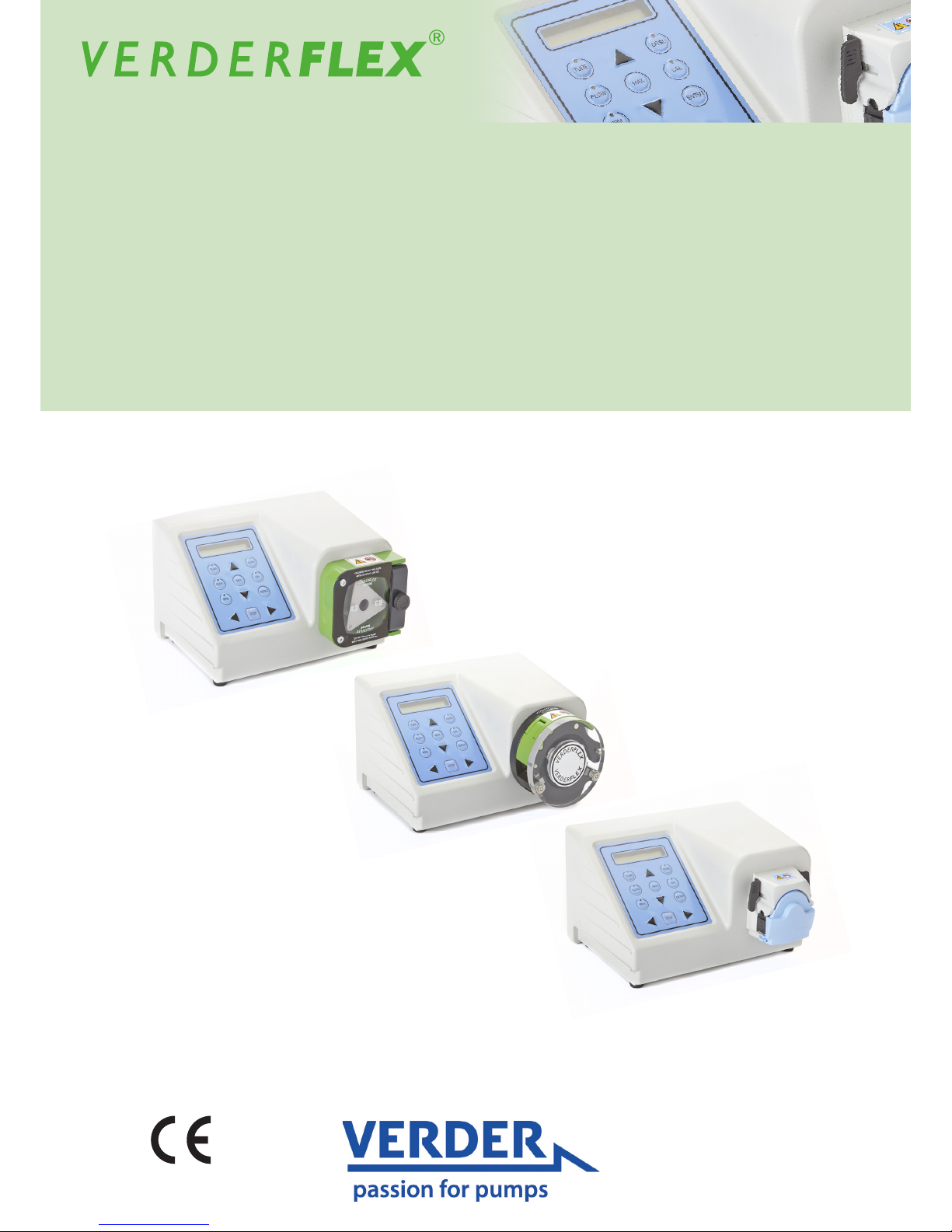
Peristaltic Cased Tube Pumps
Operating Manual Verderex Vantage 3000 P
EZ / S10 / R3i
Version 3.4v-01/2019
Print-No. 01
Page 2
Vantage 3000 P Version 3.4v-01/2019
2 | Page
Version 3.4v-01/2019
Print-No. 01
Vantage 3000 P
EZ / S10 / R3i
The information in this document is essential for the safe operation and servicing of
Verderex Vantage 3000 pumps. This document must be read and understood thoroughly prior to
installation of unit, electrical connection and commissioning.
Page 3

Vantage 3000 P Version 3.4v-01/2019
3 | Page
12 Remote Analogue/Digital Control
12.1 Types of Remote Control
12.2 Layout of Back Plate
12.3 External Controls on Different Models
12.4 Analogue Connector
12.5 Foot/Hand Switch Control
12.5.1 Connecting the Foot Switch
12.6 Analogue Control
12.6.1 Connecting Analogue Control Systems
12.7 Foot /Hand Switch Control
12.7.1 Connector Layout
12.7.2 Connector Description
12.7.3 USB Driver Installation
and Conguration
13 List of Figures and Tables
13.1 List of Figures
13.2 List of Tables
14 Declaration of Conformity
15 Appendix - Pump Specications
i Keypad Keys, Symbols and Key Combinations
1. About this Document
1.1 Key Features
2 Warranty
3 Pump Returns
4 ‘EC’ Declaration
5 Safety
5.1 Intended Use
5.2 Prevention of Obvious Misuse
6 Maintenance
7 Installation
7.1 Types of Pump Head
7.2 EZ Head
7.2.1 Key Features
7.2.2 Installing the Tube
7.2.3 Replacing the Pump Head
7.2.4 Stacking Pump Head
7.3 S10 Head
7.3.1 Key Features
7.3.2 Installing the Tube
7.4 R3i Head
7.4.1 Key Features
7.4.2 Installing the Tube
7.4.3 Changing Rotor – R3i Head
8 Functions
8.1 Adjust Flow Rate
8.2 Update Tube Size
8.3 Adjust Pump Speed
8.4 System Calibration
8.5 Recall Saved Calibration
8.6 Runback (Anti-drip)
8.7 Maximum Function Feature
8.8 Single Dose Function
8.9 Speed Ramp Function
8.10 Multi Cyclic Dosing
8.11 Batch Function
8.12 Save Dose Settings to PROG 1
8.13 Save Dose Settings to PROG 2 – 10
8.14 Recall Saved Dose Setting
8.15 Memory Dose Function
8.16 Keypad Lock Function
8.17 Analogue / Digital Remote Interface
8.18 IP66 Remote Speed Control
8.19 Pause Function
9 Software Installation
10 Menu Tree
10.1 Save Settings
10.2 Reload Settings
11 Remote Interface
11.1 Manual Mode
11.2 Memo-Dose Mode
11.3 Dose Mode
11.4 Batch Mode
Table of Contents
Page 4
Vantage 3000 P Version 3.4v-01/2019
4 | Page
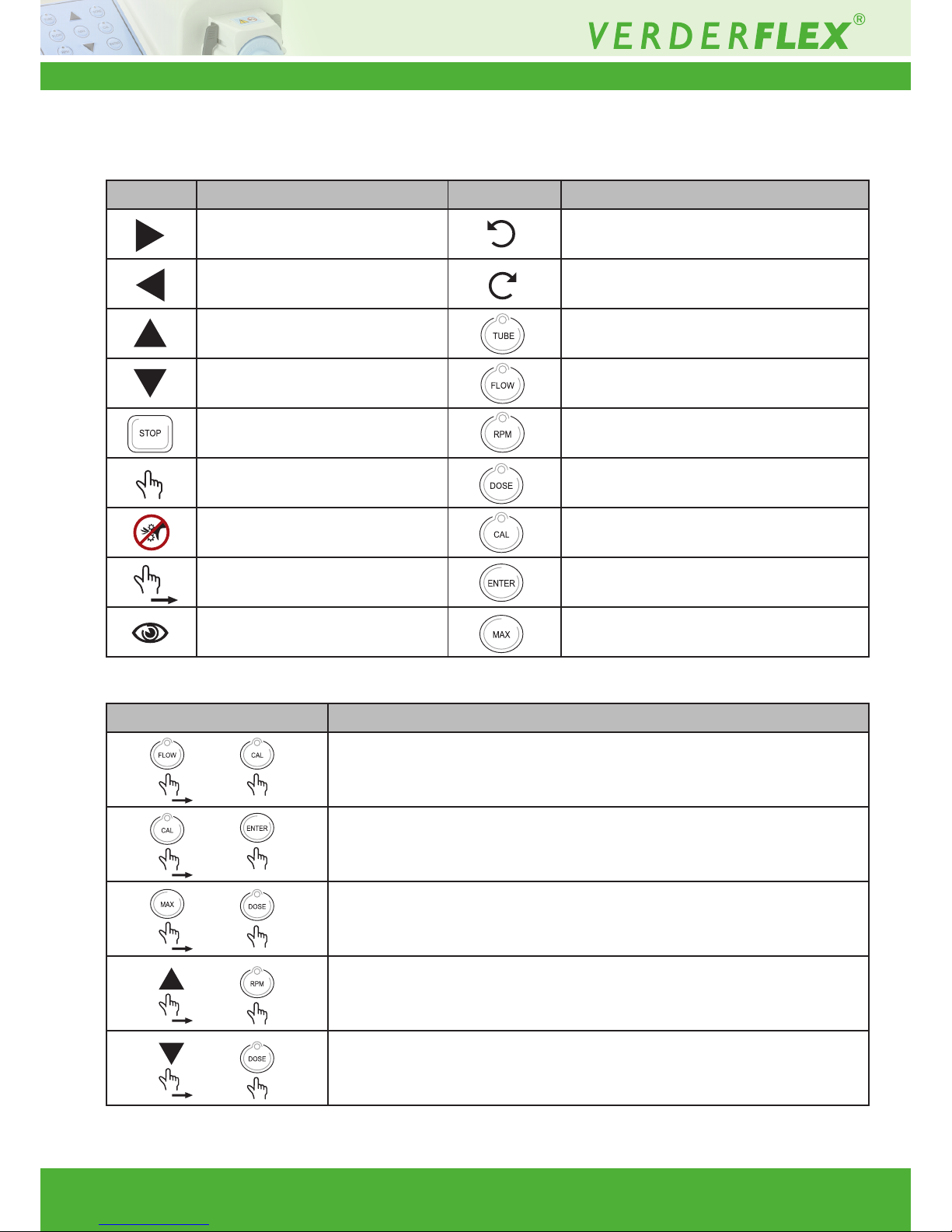
i Keypad Keys, Symbols and Key Combinations
Symbol Meaning Symbol Meaning
Start CW Counter clock wise
Start CCW Clock wise
Scroll up Select tube size
Scroll down Set ow rate
Stop Set RPM
Press Set dose parameters
Caution Calibrate
Press and hold down Enter
See Maximum
Symbol Meaning
Run Back (Anti-Drip) OFF/ON
Press and hold down FLOW then press CAL
Calibrate SAVE/RECALL
Press and hold down CAL then press ENTER
Batch Facility SET number of Doses Press
and hold down MAX then press DOSE
Speed Ramp OFF/ON
Press and hold down UP then press RPM
Save Dose settings
Press and hold down UP then press DOSE
Table 1 Keypad Keys and Symbols
Table 2 Keypad Key Combinations
Page 5
Vantage 3000 P Version 3.4v-01/2019
5 | Page
1 About the Product
The Verderex Vantage 3000
®
range of peristaltic
pumps deliver highly accurate and repeatable ow
rates with a quick and easy setup. Vantage 3000 P
is a programmable, easy tube load pump with
a stackable pump head and requires low maintenance.
1.1 Key Features
- Microprocessor controlled 24 hour duty with brushless dc
motor
- Set precise dose requirement and calibrate to suit medium viscosity
- Stackable and multi channel head options
- Keypad operated with two line alpha numeric display.
- Volt free contacts for external Start/Stop/Reverse
- Manual/ analogue/Computer control of speed/ow rate
- Store 10 settings (jobs) for easy start up
- Memory Dose
- Speed Ramp (Soft Start) Facility
- Keypad Lock
- Computer link – up with RS232
- WindowsTM based application programming.
2 Warranty
The manufacturer does not accept any liability for
damage resulting from disregard of this documentation.
This product is guaranteed to be free from defects
in material or workmanship for a period of 24 months
from date of purchase, excluding consumable items
such as cartridges, tubing or rollers. Products out
of guarantee period will be repaired for a nominal charge.
3 Pump Returns
All returned pumps must be decontaminated before
being returned. The Decontamination Certicate
is separately requested and must be returned before
or with the pump delivery. For your protection, items
returned must be carefully packed to prevent
damage in transit and insured against loss.
4 ‘EC’ Declaration
The Vantage 3000 P range, complies with EMC 2014/
30/ EU as well as Machine Directive 2006/42/EC.
Installation of this pump into other equipment must
be in accordance with relevant Directives/Standards
and be carried out by a suitably competent person.
5 Safety
The manufacturer does not accept any liability for
damage resulting from disregard of this documentation.
5.1 Intended Use
• Only use the pump to handle compatible uids
as recommended by the manufacturer.
• Adhere to the operating limits.
• Consult the manufacturer regarding any other use
of the pump.
5.2 Prevention of Obvious Misuse
• Note the operating limits of the pump with regard
to temperature, pressure, ow rate and motor speed.
• Do not operate the pump while the inlet/outlet valve
is closed.
• Only install the pump as recommended in this manual.
For example, the following are not allowed:
– Installing the pump without proper support.
– Installation in the immediate vicinity of extreme
hot or cold sources.
• Do not use in conjunction with life support equipment
• Do not connect pump to the human body
Risk of electrocution!
u Make sure that the electrical information on the
rating plate agrees with the power supply.
u Isolate the main supply before replacing the tube
/cartridge
u Isolate the main supply before removing the
enclosure cover
DANGER
Page 6
Vantage 3000 P Version 3.4v-01/2019
6 | Page
6 Maintenance
Motor and Gearbox are lubricated for life and should
not require attention. Rotor rollers are self-lubricated.
Pump tubing will not last forever; establish suitable
tube replacement schedule to prevent inconvenient
tube failure.
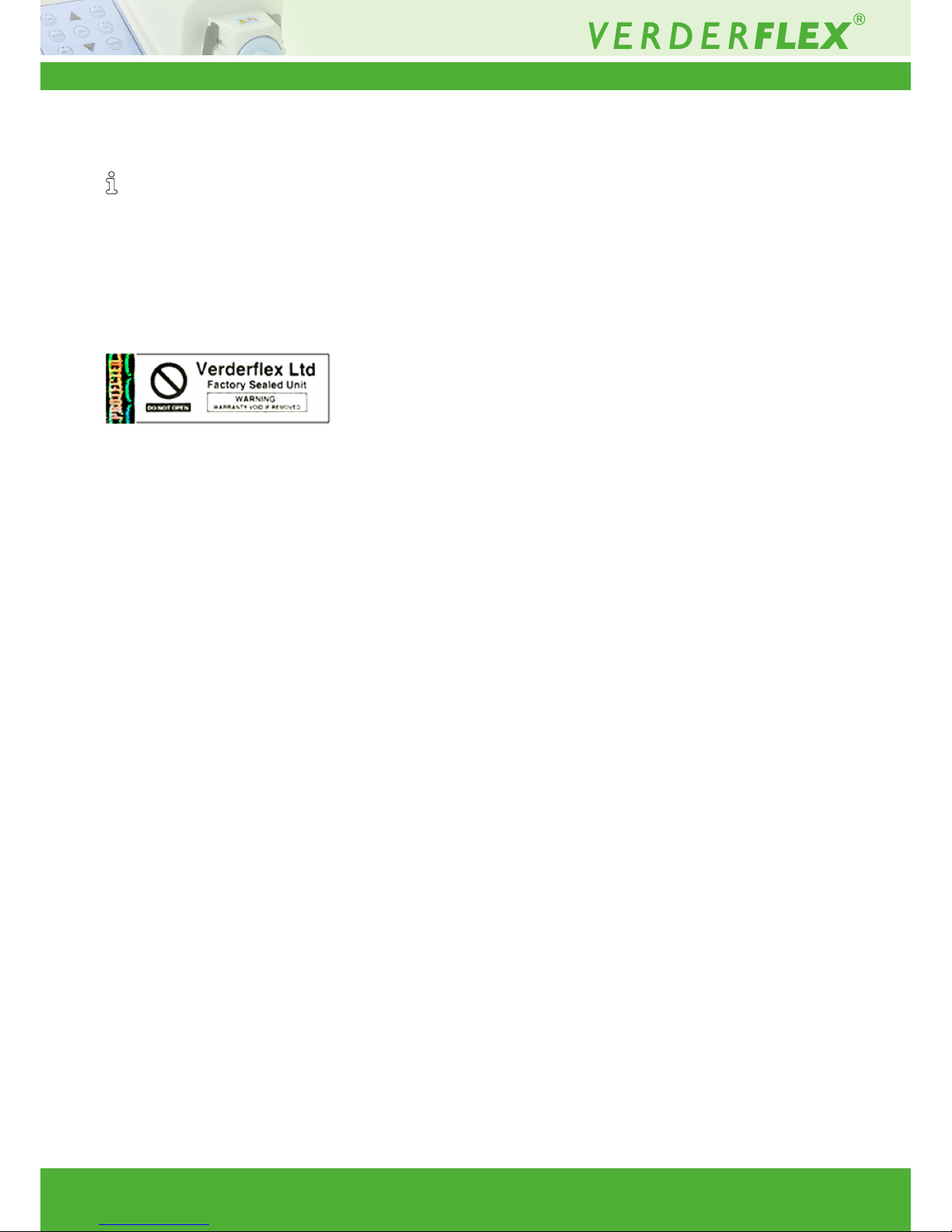
This pump contains no user serviceable parts and
is factory sealed to conrm integrity. Pump warranty
will be invalidated if the seal is broken.
Figure 1 Tamper Proof Lable
7 Installation
- Pump should be installed by suitably qualied
personnel
- Pump should be sited on stable horizontal surface
- Allow free ow of air around pump
- Tube should not be allowed to kink.
Page 7
Vantage 3000 P Version 3.4v-01/2019
7 | Page
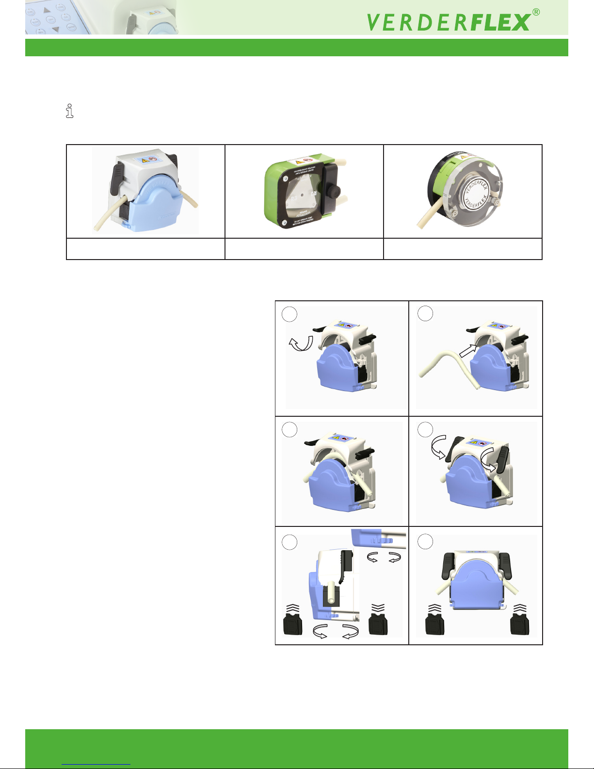
7.1 Types of Pump Head
Verderex® Vantage 3000 P pumps are available with the S10 pump head featured on the Verderex Smart tube pump,
as well as the R3i head featured on the Verderex Rapide tube pump providing greater ow rates with stackable
and multi channel head options.
7.2 EZ Head
7.2.1 Key Features
Easy tube change system, stackable multi
head options with Verderprene, Silicone,
Viton® or Tygon® tubing.
• Flow rates up to 1,310 ml/min
(20.8 US GPH)
• Pressures up to 2 Bar (29 PSI)
• Typically used in frequent tube change
applications
7.2.2 Installing the Tube
1. Flip the lugs on both sides of the pump head
to lift the top section
2. Once the head is lifted as shown in gure,
insert the tube over the rollers.
3. Flip the lugs on both sides of the pump head
to lock the top section down.
- Adjust the tube clamp to hold the tube
in place and avoid slip
- Adjust the tube clamp on both sides
of the pump head to the tube diameter.
- If a tube slip is observed, tighten the
tension on the clamps
- Alternately, if a reduced ow is observed,
reduce the clamp tension.
Table 4 Installing the Tube
Table 3 Vantage 3000 P Pump Head Options
1
1. EZ Head 2. R3i Head 3. S10 Head
2
3 4
5
6
Page 8
Vantage 3000 P Version 3.4v-01/2019
8 | Page
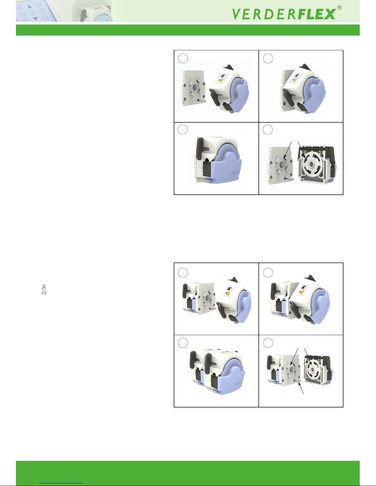
Table 5 Replacing Pump Head – EZ Head
Table 6 Stacking – EZ Head
7.2.3 Replacing the Pump Head
– EZ Head
1. Offer pump head to backplate at angle
locating drive shaft and rotor shaft with
pump head at approx 45° to vertical,
locating backplate lugs in housing.
2. Push and twist until location lever clicks
into position.
3. Remove by depressing location lever and
twisting pump head counter clockwise 45°.
7.2.4 Stacking Pump Head
– EZ Head
A pump head can be stacked over a similar
stackable head as demonstrated in table 6.
1. Attach the stackable head on to
the backplate (refer 7.2.3 )
2. Offer the pump head over the stackable
head locating the drive shaft and pump
shaft with pump head at approx 45°
to vertical, locating lugs in the housing.
3. Push and twist unit location lever
clicks into position.
4. Remove by depressing location lever
on the stackable head and twisting
pump head counter clockwise 45°.
Location lugs
Location lugs
Location lever
1 2
3 4
1 2
3 4
Page 9
Vantage 3000 P Version 3.4v-01/2019
9 | Page
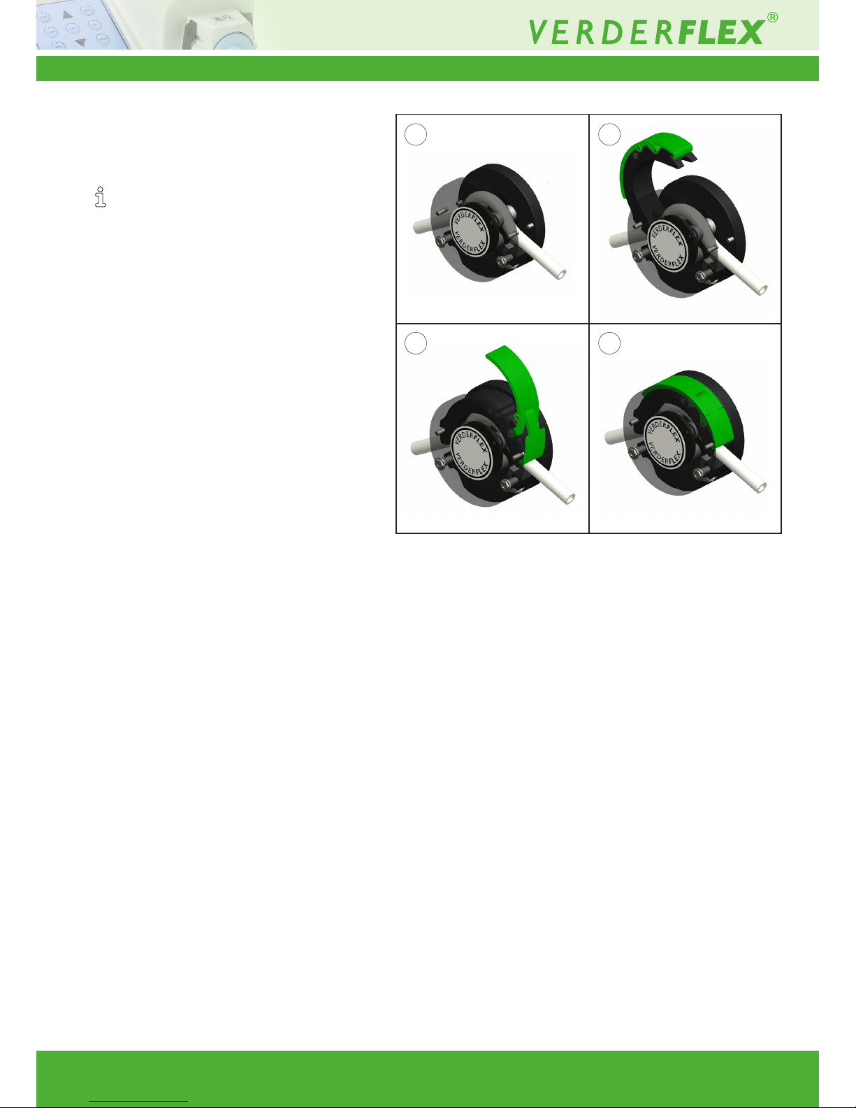
Table 7 Installing Tube – S10 Head
7.3 S10 Head
7.3.1 Key Features
Taken from the Verderex Smart tube
pump design. The S10 includes a quick tube
change, ergonomic design for ease of use.
• Flow rates up to 1,780 ml/min (28 US GPH)
• Pressures up to 2 Bar (29 PSI)
• Multi channel options
• Typically used in:
- Chemical dosing
- Industrial uid transfer
- Heavy duty environments
7.3.2 Installing the Tube
1. Insert tube on top of the rollers
2. Fit the saddle to one set of dowels
3. Open up the lever and t the claw over
4. Push the lever down to lock the saddle
into place over the other set of dowels
3 4
1 2
Page 10
Vantage 3000 P Version 3.4v-01/2019
10 | Page
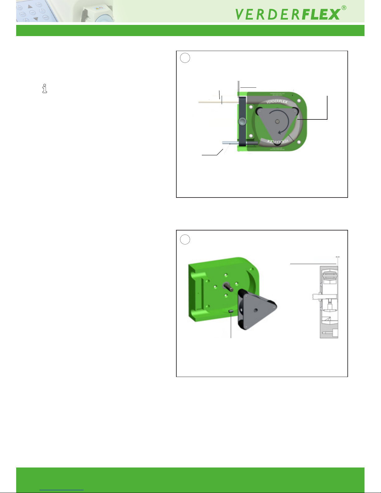
Fastening grub screw
Rotor setting
distance
2.5mm
Feed tube carefully
from inlet side
Blunt rod to
guide tube
Align tube marks
Protective front
cover remains
in place
Table 8 Installing Tube – R3i Head
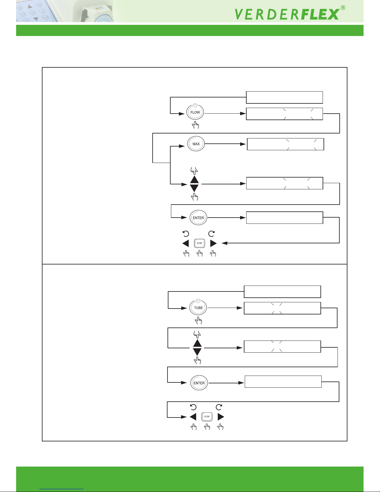
Table 9 Replacing the Rotor – R3i Head
7.4 R3i Head
7.4.1 Key Features
Robust design with thick wall tube for suction
and pressure handling.
• Flow rates up to 3,250 ml/min
(51.5 US GPH)
• Pressures up to 2 Bar (29 PSI)
• Typically used in:
- Printing production
- Dispensing
- Industrial detergent applications
7.4.2 Installing the Tube
1. Remove the clamp, but leave the front
cover in place
2. Run the pump at low speed and carefully
feed tube through the inlet
3. When tube reach outlet,use blunt end
rod to guide the tube out.
4. Fit tube clamp loosely, and position tube
with marked lines adjecent to edge of
pump housing and tube clamp.
5. Tighten the tube clamp securely
7.4.3 Changing Rotor – R3i Head
1. Align grub screw hole with at on shaft
2. Align peak of roller with peak of tube track
or set rotor distance back from front of
pump housing
3. Fasten grub screw securely
1
2
Page 11
Vantage 3000 P Version 3.4v-01/2019
11 | Page
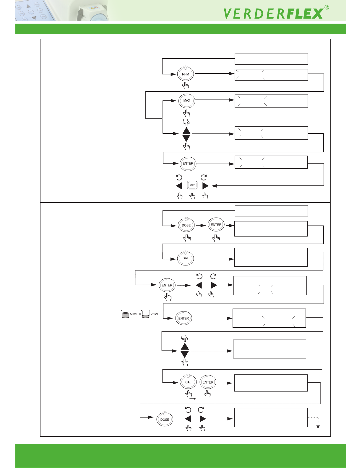
8 Functions
Description
8.1 Adjust Flow Rate
8.2 Updating Tube Size
Key combination Display
150 RPM 80 788ML/MN
100 RPM 80 525ML/MN
100 RPM 80 525ML/MN
150 RPM 80 788ML/MN
250 RPM8 0 1313ML/MN
100 RPM 80 525ML/MN
100 RPM 80 525ML/MN
100 RPM 48 525ML/MN
100 RPM 48 525ML/MN
Page 12
Vantage 3000 P Version 3.4v-01/2019
12 | Page
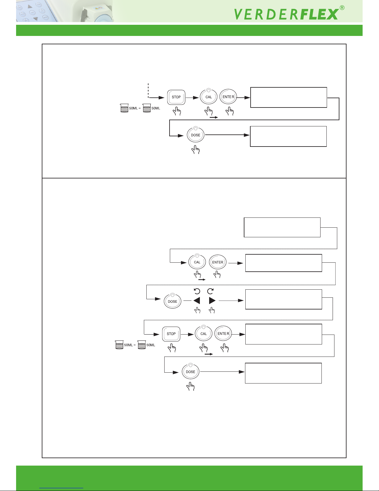
Description
8.3 Adjust Pump Speed
8.4 System Calibration
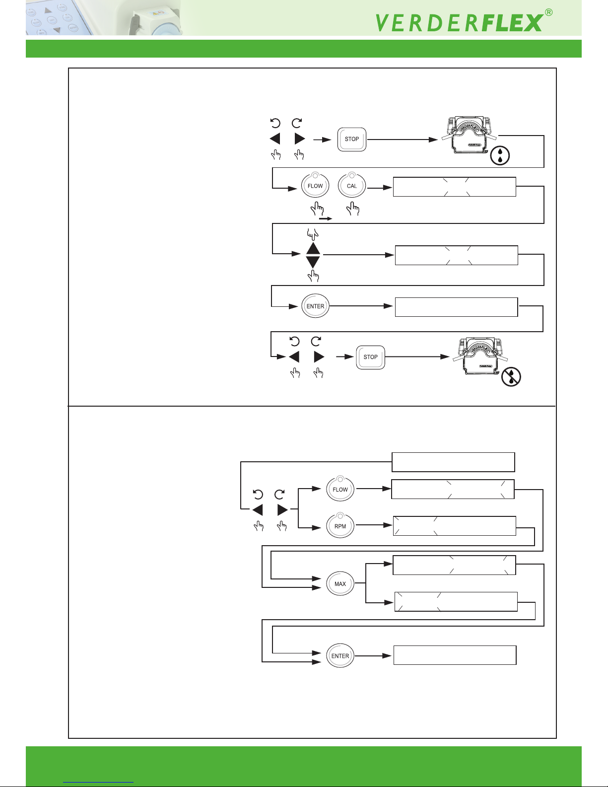
• Press “Calibrate button” to enter
calibration mode.
• Measure uid dose manually.
• If measured dose is
different from required,
enter the measured
value.
• Press and hold Calibrate button
& then press “enter”.
• Press dose button and then
run the pump to check
measured dose.
Key combination Display
100 RPM 80 525ML/MN
100 RPM 80 525ML/MN
250 RPM
80 525ML/MN
50 RPM
50 RPM
100 RPM 80 ---M L/MN
050.0 ML >>0 25.0 ML
100 RPM 80 525ML/MN
100 RPM 80 525ML/MN
050.0 ML >> 050.0 ML
100 RPM 80 525ML/MN
050.0 ML
>> 050.0 ML
100 RPM 80 525ML/MN
050.0 ML >> 050.0 ML
100 RPM 80 525ML/MN
050.0 ML >> 025.0 ML
100 RPM 80 ---M L/MN
050.0 ML >>0 25.0 ML
Pump calibrated
80 525ML/MN
80 525ML/MN
100 RPM 80 525ML/MN
ML 002.0 S INT
100 RPM 80 525ML/MN
050.
050.0
X 2
• Press “Dose button” to enter
dose mode.
Note: Enter the volume to be dosed or
calibrated, with min. 2 sec interval.
Page 13
Vantage 3000 P Version 3.4v-01/2019
13 | Page
Description Key combination Display
100 RPM 80 525M L/MN
050.0 ML >>0 25.0 ML
X 2
100 RPM 80 525ML/MN
• To exit calibration mode,
• Press “stop”,
• Press & hold calibrate button,
Press “enter”,
• Press dose button twice (you
are now back to home screen).
• Press and hold Calibrate button
& then press “enter”.
• Press dose button and then
run the pump to check
measured dose.
Exit Calibration
• To exit calibration mode,
• Press “stop”
• Press & hold calibrate button,
Press “enter”
• Press dose button twice (you
are now back to home screen).
100 RPM 80 ---M L/MN
050.0 ML >>0 25.0 ML
100 RPM 80 525ML/MN
100 RPM 80 ---M L/MN
050.0 ML >>0 25.0 ML
100 RPM 80 525M L/MN
050.0 ML >>0 25.0 ML
X 2
100 RPM 80 525ML/MN
Exit Calibration
8.4 System Calibration (continued)
8.5 Recall Saved Calibration
Page 14
Vantage 3000 P Version 3.4v-01/2019
14 | Page
Description Key combination Display
RUNBACK: OFF
RUNBACK: OFF
100 RPM 80 525ML/MN
100 RPM 80 525ML/MN
100 RPM 80 525ML/MN
100 RPM 80 525ML/MN
250 RPM 80 1313ML/MN
250 RPM 80 1313ML/MN
250 RPM 80 1313ML/MN
8.6 Runback (Anti-drip)
8.7 Maximum Function
Feature
Page 15
Vantage 3000 P Version 3.4v-01/2019
15 | Page
Description
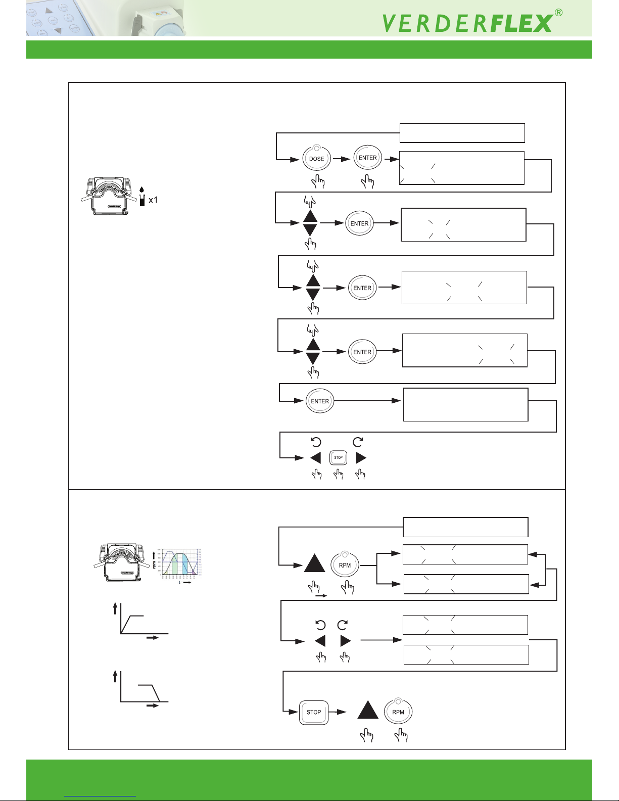
8.8 Single Dose Function
8.9 Speed RAMP Function
Key combination Display
100 RPM 80 525ML/MN
262.5 ML 002.0 S INT
100 RPM 80 525ML/MN
100 RPM 80 525ML/MN
300.0 ML 002.0 S INT
100 RPM 80 525ML/MN
300.0 ML 002.0 S INT
100 RPM 80 525ML/MN
262.5 ML 000.0 S INT
100 RPM 80 525ML/MN
262.5 ML 000.0 S INT
150R PM 80 525ML/MN
150 RAMP 80 525ML/MN
150 RPM 80 525ML/MN
150 RAMP 80 525ML/MN
150 RPM 80 5 25ML/MN
rpm
t
rpm
t
Exit
Function
Note: For calibration settings, before dosing
function refer to (g8.4 System Calibration) and (g8.5 Recall Saved Calibration).
Page 16
Vantage 3000 P Version 3.4v-01/2019
16 | Page
Description Key combination Display
100 RPM 80 525ML/MN
262.5 ML 002.0 S INT
100 RPM 80 525ML/MN
100 RPM 80 525ML/MN
300.0 ML 002.0 S INT
100 RPM 80 525ML/MN
300.0 ML 002.0 S INT
100 RPM 80 525ML/MN
262.5 ML 005.0 S INT
100 RPM 80 525ML/MN
262.5 ML 005.0 M INT
100 RPM 80 525ML/MN
100 RPM 80 525ML/MN
050.0M L 0 02.0 S INT
BATCH
-----
OF 000
050.0M L 0 02.0 S INT
BATCH
-----
OF 015
050.0M L 0 02.0 S INT
BATCH
015
OF 015
050.0M L 0 02.0 S INT
100 RPM 80 525ML/MN
050.0M L 0 02.0 S INT
Exit Function
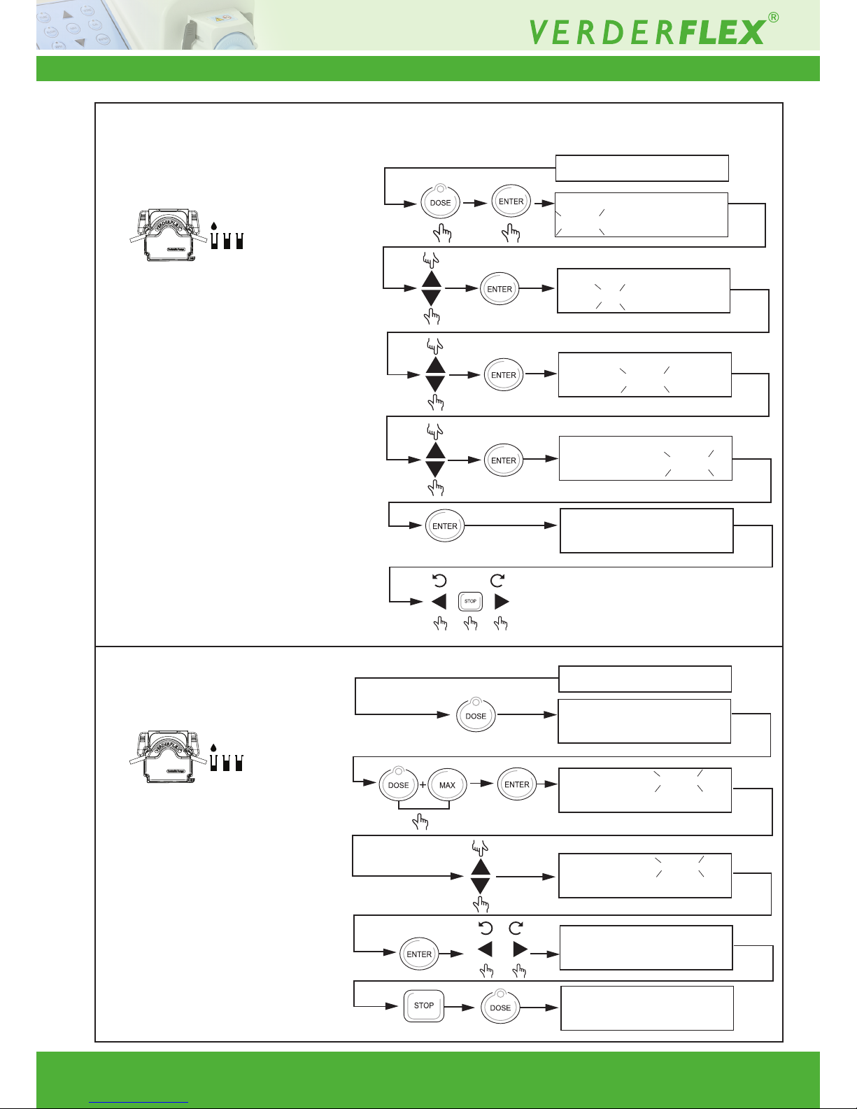
Note: For calibration settings, before dosing
function refer to (g8.4 System Calibration) and (g8.5 Recall Saved Calibration).
Note: Dose and Max button has to be
pressed together, at the same
time to activate Batch function.
8.10 Multi Cyclic Dosing
8.11 Batch Function
Page 17
Vantage 3000 P Version 3.4v-01/2019
17 | Page
Description
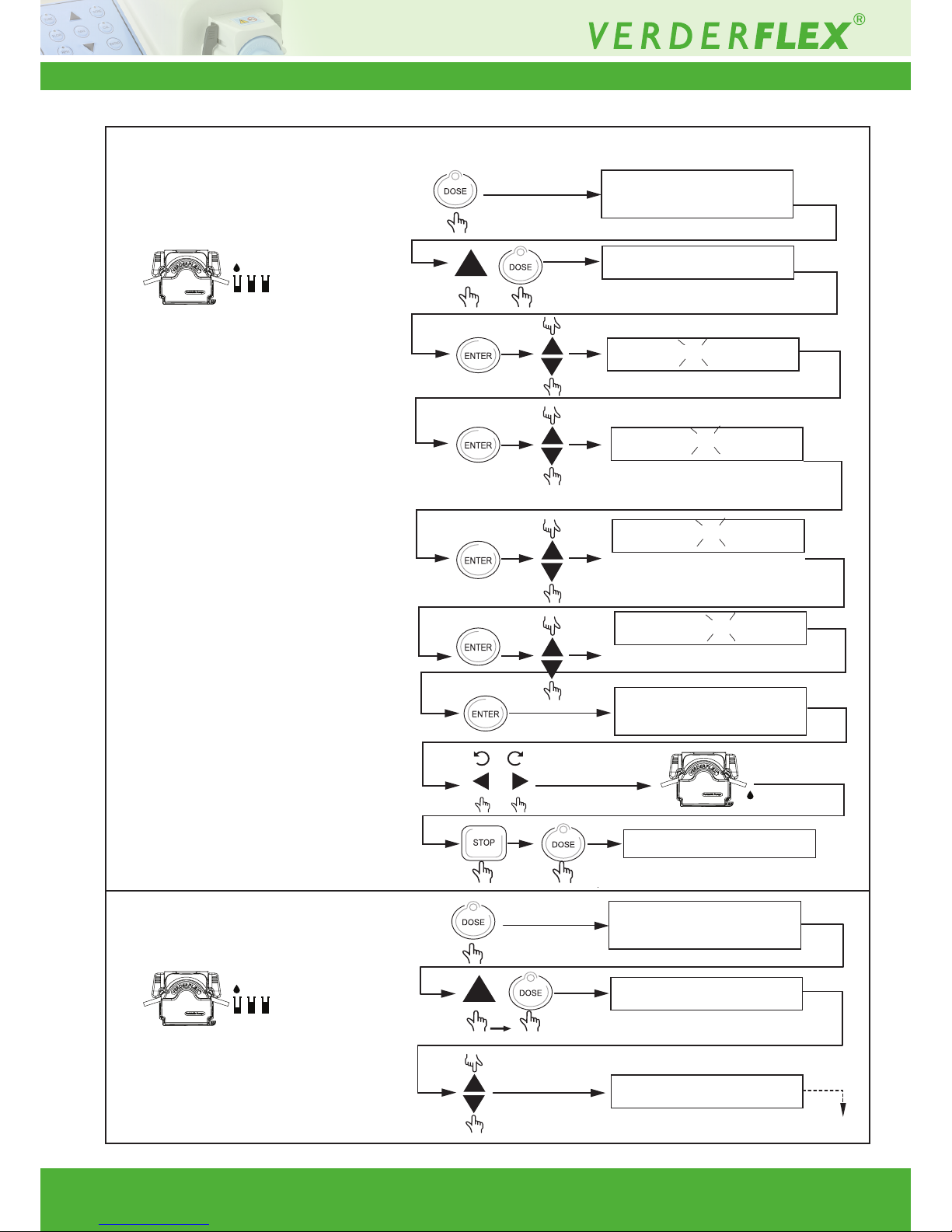
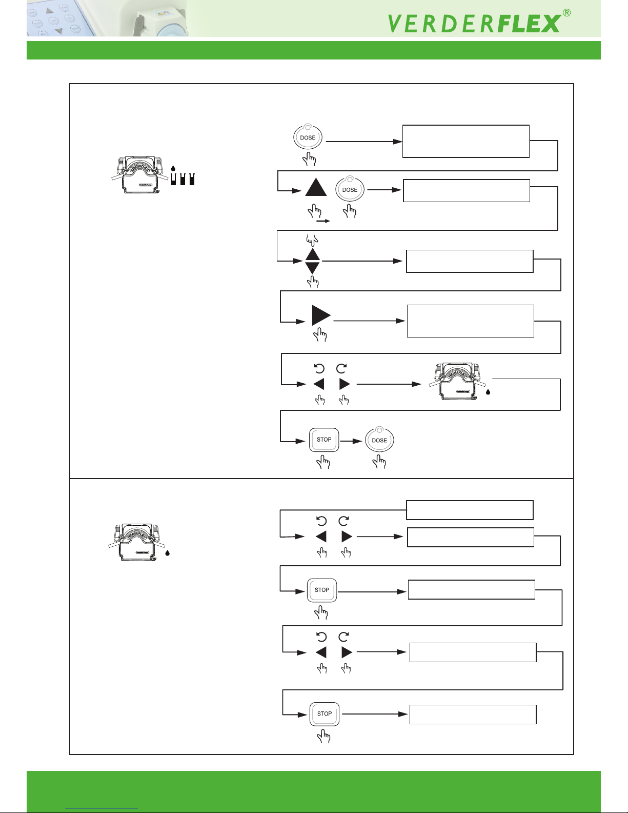
8.12 Save Dose Settings
to PROG 1
8.13 Save Dose Settings to
PROG 2 - 10
Key combination Display
100 RPM 48 235ML/MN
150.0M L 002.0 S INT
PROG1 AAAA
PROG1 OAAA
PROG1 OIAA
PROG1 OILA
PROG1 OIL1
OIL1 48 235ML/MN
150.0M L 002.0 S INT
100 RPM 48 235ML/MN
100 RPM 48 235ML/MN
150.0M L 002.0 S INT
PROG1 OIL1
PROG7 AAAA
Exit Function
Continued same as for PROG 1
Page 18
Vantage 3000 P Version 3.4v-01/2019
18 | Page
Description
8.14 Recall Saved Dose
Setting
8.15 Memory Dose Function
Key combination Display
100 RPM 48 235ML/MN
150.0M L 002.0 S INT
PROG1 OIL 1
PROG7 LIM E
LIM E 48 470ML/MN
250.0M L 002.0 S INT
100 RPM 80 525ML/MN
100 RPM 80 525ML/MN
x2(0.5 Sec)
100 RPM MD 525ML/MN
100 RPM MD 525ML/MN
x2(0.5 Sec)
100 RPM 80 525ML/MN
Exit Function
Dosing period for previous dosing saved
Repeat memory dose
Exit Function
Page 19
Vantage 3000 P Version 3.4v-01/2019
19 | Page
Description Key combination Display
100 RPM 80 525ML/MN
100 RPM LK5 25ML/MN
100 RPM 80 525ML/MN
Keypad locked
Keypad unlocked
(2+ sec)
All keys except for pumping
and stop button
(2+ sec)
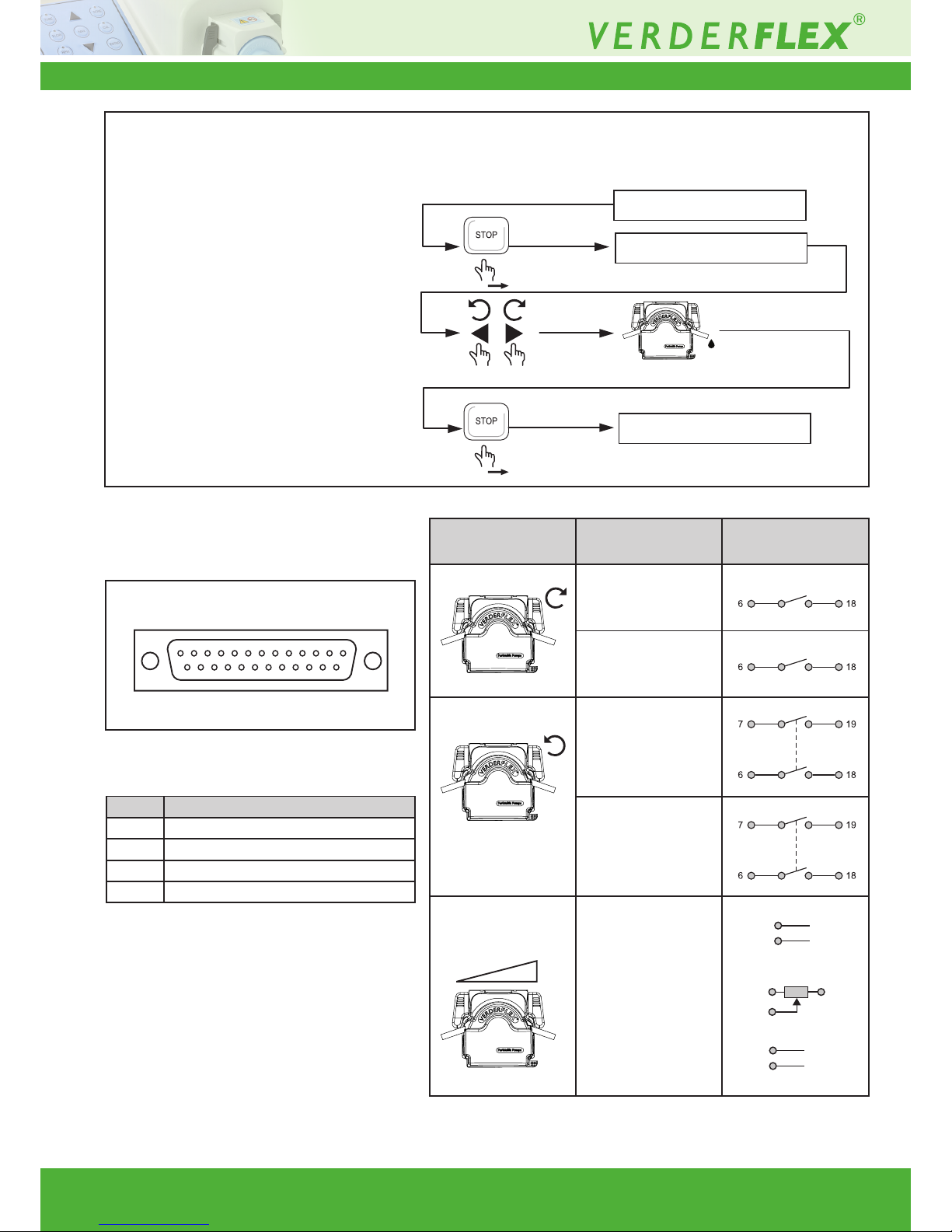
8.17 Analogue /Digital
Remote Interface
Figure 2 25 Way ‘D’ Type Connector (Remote
Control Lead P/N: AU E1973
PIN Function
14 pump running +5V out
15 pump stopped +5V out
21 pump running GND
22 pump stopped GND
Function Connection
Clockwise Started CW
Stopped CW
Counter Clockwise Started CCW
Stopped CCW
IP 66 Remote
speed control
Speed control
0-10V d.c
RPM
13
25
01
14
13 +V
25 GND
10
11
23
10K (0.5W)
12 +V
24 GND
Table 10 Analogue /Digital Remote Interface
8.16 Keypad Lock Function
Page 20

Vantage 3000 P Version 3.4v-01/2019
20 | Page
Description
8.18 IP 66 Remote Speed
Control
Key combination Display
100 RPM 80 525ML/MN
SPEED CTRL: INTERNAL
SPEED CTRL: EXT VOLT
SPEED CTRL: EXT CURR
SPEED CTRL: EXT POT.
0 –1 0V DC
4 –2 0 mA
-----R PM 80 ----- ML/MN
Remote potentiometer
8.19 Pause Function
100 RPM 80 525ML/MN
100 RPM 80 525ML/MN
050.0M L 0 02.0 S INT
PPP RPM 80 PPPP ML/MN
PPPPPML PPPPP S INT
100 RPM 80 525ML/MN
050.0M L 0 02.0 S INT
100 RPM 80 525ML/MN
PUMP PAUSED
Note:
The PAUSE Function can be used to
pause the dosing fuction in dose mode
and in Batch dose mode
The PAUSE function can be activated
when the pump is running.
Page 21
Vantage 3000 P Version 3.4v-01/2019
21 | Page
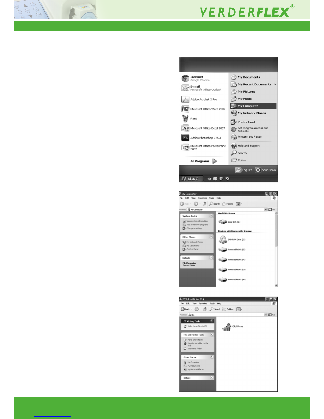
9 Software Installation
Insert the installation disc and open
“My computer” from start menu
Click and open CD/DVD drive
Copy and paste “PCPUMP.exe” onto the
desktop or into preferred folder
Page 22
Vantage 3000 P Version 3.4v-01/2019
22 | Page
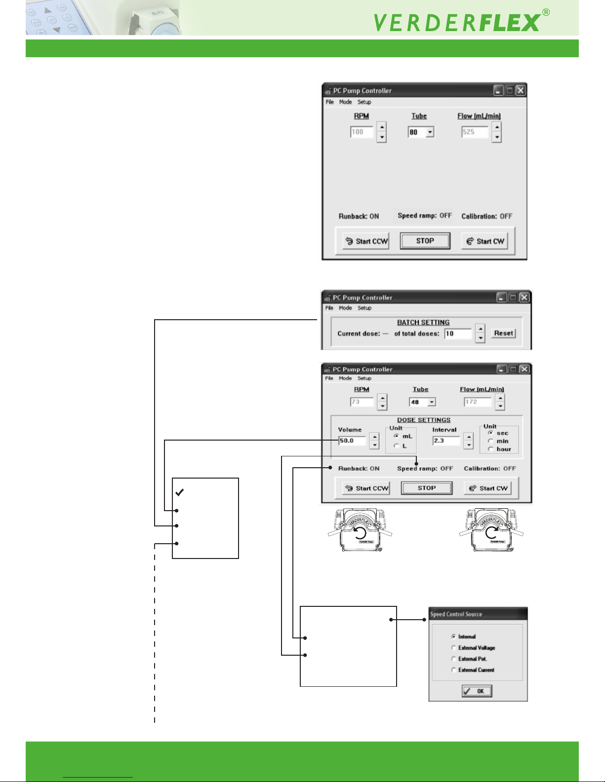
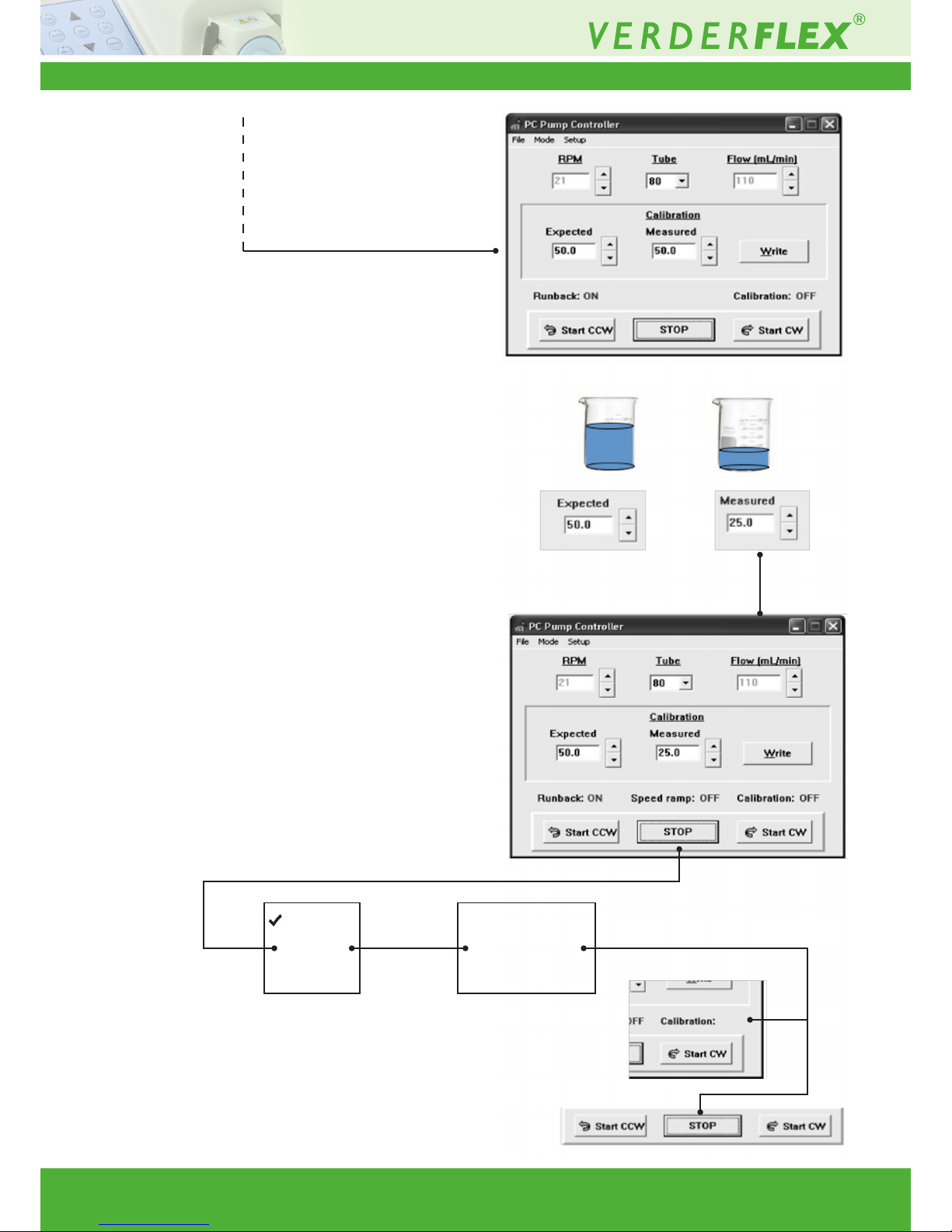
10 Menu Tree
Run “PCPUMP.exe”
Normal
Dose
Batch
Calibrate
Speed control . . .
Runback
Speed Ramp
Use calibration
Page 23
Vantage 3000 P Version 3.4v-01/2019
23 | Page
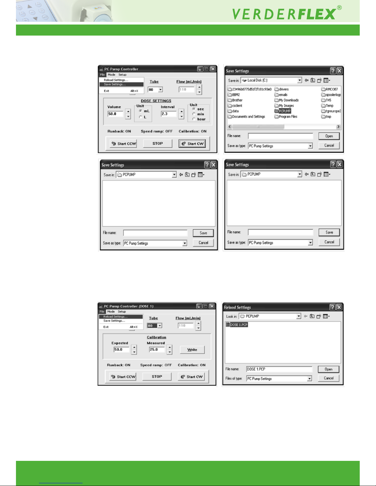
Normal
Dose
Calibrate
Speed control . . .
Runback
Use calibration
ON
Page 24
Vantage 3000 P Version 3.4v-01/2019
24 | Page
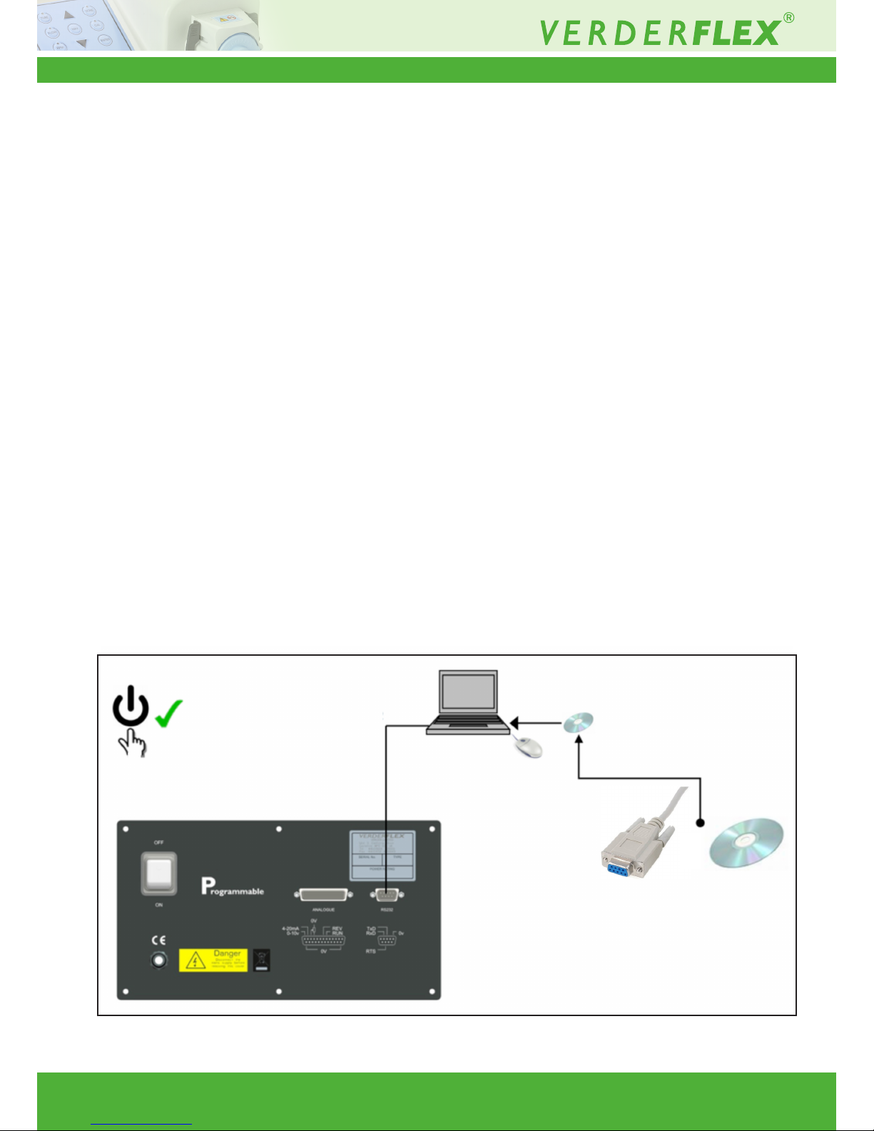
10.1 Save Settings
10.2 Reload Settings
Page 25
Vantage 3000 P Version 3.4v-01/2019
25 | Page
11 Remote Interface
11.1 Manual Mode
• Momentarily operate CW or CCW run from keypad and the
pump runs until STOP is pressed.
• Momentarily operate CW or CCW run from remot interface
and the pump only runs for as long as the input is on. Continuous operation requires the input to be maintained.
11.2 Memo-Dose Mode
• Momentarily Operate CW or CCW run from keypad and
the pump runs for that memo period then stops.
• Momentarily operate CW or CCW run from keypad again
and the operation repeats as a “One shot operation”.
• Operate CW or CCW run from remote interface and the
pump only runs for as long as the input is on. The input
must be maintained throughout the duration of the dose
period for the dose cycle to complete. When the Memodose has completed, the input must then be unlatched and
re-latched again to allow the Memo-dose to restart.
11.3 Dose Mode
• Momentarily operate CW or CCW run from keypad and the
Dose program repeats indenitely.
• Operate CW or CCW run from the remote interface and
the pump will run the dose cycle then stop at the end of
one dose (“One shot”) unless the input is maintained.
Maintaining the input allows the dose to repeat indenitely
(“cyclic”)
11.4 Batch Mode
• Momentarily operate CW or CCW run from keypad and the
batch program runs.
• The batch count decrements automatically when the timeout period of the previous batch count has elapsed.
• Operate CW or CCW run from the remote interface and
the pump will dose one batch count then stop at the start
of the next batch count, unless the input is maintained.
Maintaining the input allows the batch to continue its decrement count until it reaches zero. If the input is not maintained it can be decremented as a “One shot” operation by
momentarily tripping the remote input until count = zero.
*(Please Note: Keypad operation has priority over the remote
interface)
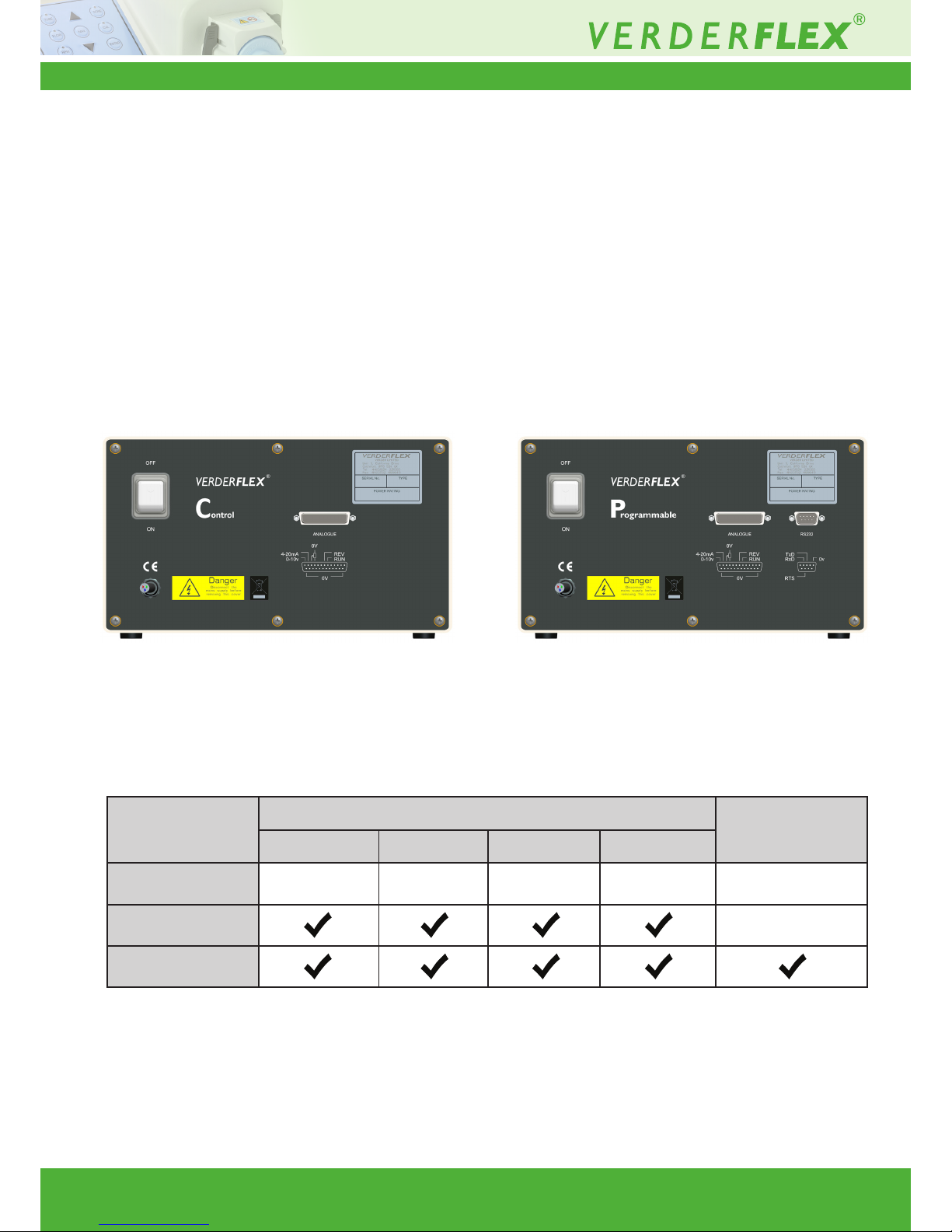
Figure 3 IP66 Computer Control
(3: TURN ON PUMP)
(2: INSTALL PC PUMP PROGRAM)
(1: INSERT DISC)
IP 66 SOFTWARE BUNDLE
PROGRAMMABLE DISPENSER
NULL MODEMRS232
(IP66)
Page 26
Vantage 3000 P Version 3.4v-01/2019
26 | Page
12 Remote Analogue/Digital Control
An external Analogue/Digital control can be used to operate the Vantage 3000 C & P range. Suitable IP66 and RS232
connectors are available for external connections.
12.1 Types of Remote Control
• Foot/Hand switch
• Analogue control:
- 0 - 10V D.C
- Remote potentiometer
- 4 – 20 mA
• RS232 control
12.2 Layout of Back Plate
Figure 4 Back Plate – Vantage 3000 C Figure 5 Back Plate – Vantage 3000 P
12.3 External Controls on Different Models
The control methods featured on each model are as listed below:
Model
Analogue/Digital Control
RS232 Control
Footswitch 0-10V d.c 4-20mA 0-5V
Vantage 3000 B
Vantage 3000 C
Vantage 3000 P
Table 11 Models & Control Features Available
Page 27
Vantage 3000 P Version 3.4v-01/2019
27 | Page27 | Page
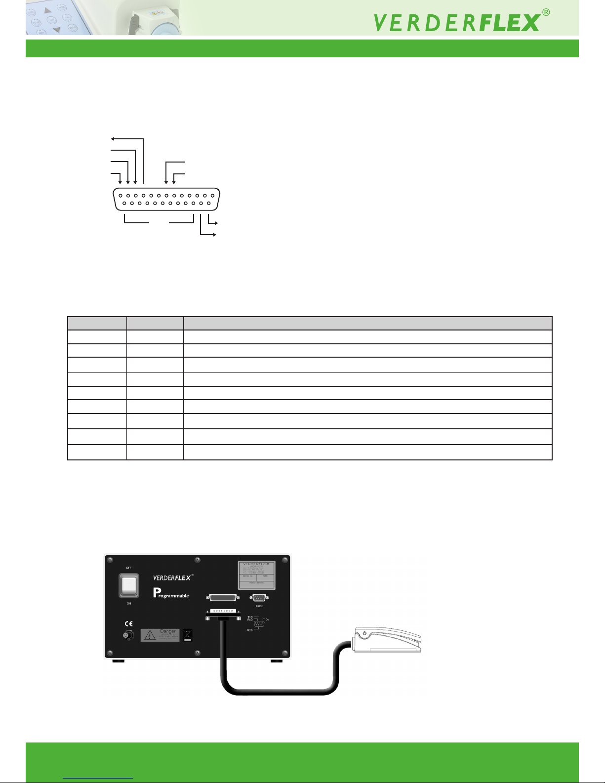
12.4 Analogue Connector
• Connector Layout
Figure 6 25 Way ‘D’ Type Connector
• Connector Description:
12.5 Foot /Hand Switch Control
Foot switches can be used to remotely turn the pump on and off, freeing the hands to perform other operations or
providing ergonomic improvement at a workstation.
Figure 7 Connecting the Footswitch
PIN I/O FUNCTION
6 IN FORWARD RUN INPUT
7 IN REVERSE RUN INPUT
10 OUT 5 VOLT SUPPLY (to potentiometer)
11 IN 0-5 VOLTS INPUT
12 IN 4-20mA INPUT
13 IN 0-10 VOLTS INPUT
14 OUT RUNNING OUTPUT (5V)
15 OUT STOPPED OUTPUT (5V)
16 to 25 OUT 0 VOLTS (internally connected to zero volts in the pump)
Table 12 Analogue/Digital Connector Pins
Footswitch
25 way “D” connector
Vantage 3000
13
25
1
14
5V
0-5V
4-20mA
0-10V
REV I/P
RUN I/P
RUN O/P
OV
STOP O/P
Page 28
Vantage 3000 P Version 3.4v-01/2019
28 | Page28 | Page
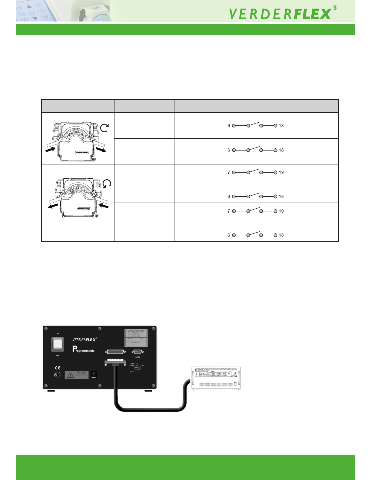
12.5.1 Connecting the Foot Switch
Connect the footswitch to the port marked “Analogue” of the Vantage 3000. (Refer g.3)
Only the user can be aware of all conditions and factors present during installation, operation, and maintenance
of a foot switch and surrounding work area. Therefore, only the user can determine which footswitches and which
point-of-operation safeguards can properly be used in a particular application or work station.
Figure 8 Connecting Variable Voltage/Current Source
12.6 Analogue Control
Analogue control can be used to remotely control the pump speed. 0-10V or 4-20mA can be generated by
a suitable transducer or a process controller such as a PLC. Potentiometer control utilizes the 5 volt source from
pin 10 on the 25way “D” connector and pin 11 as a 0 – 5 volt input as shown in Table 10.
Function Connection
Clockwise Started CW
Stopped CW
Counter Clockwise Started CCW
Stopped CCW
Variable Voltage/Current
source
25 way “D” connector
Vantage 3000
Table 13 Pin Function & Connection
Page 29
Vantage 3000 P Version 3.4v-01/2019
29 | Page29 | Page
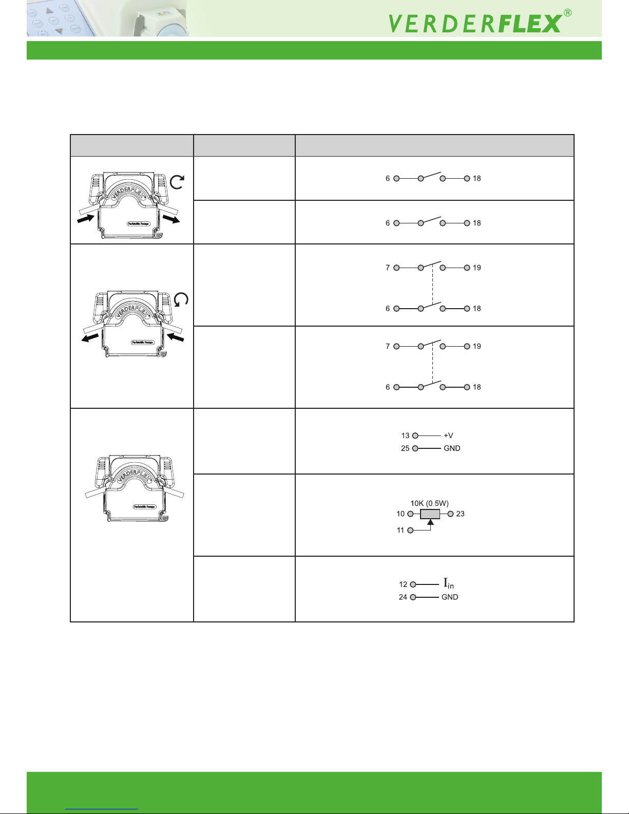
12.6.1 Connecting Analogue Control Systems
Connect the analogue control device to the Analogue port of the Vantage 3000 as shown in g 3.
Function Connection
Clockwise Started CW
Stopped CW
Counter Clockwise Started CCW
Stopped CCW
IP 66 Remote speed control Speed control
0-10V d.c
Potentiometer
4-20mA
Table 14 Pin Connection for Analogue Control (refer table 2 for pin description)
Page 30
Vantage 3000 P Version 3.4v-01/2019
30 | Page30 | Page
12.7 Foot /Hand Switch Control
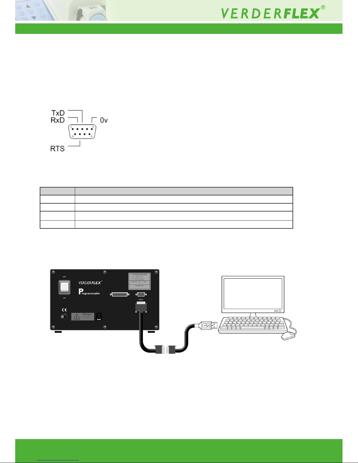
Verderex Vantage 3000 pump model “P” has an RS232 computer interface for communication with process controllers and Verderex PC windows user software. The pump can be connected to a PC/Laptop using a Null Modem serial cable and/or a USB/RS232
convertor. The USB/RS232 convertor is required only if your PC/Laptop is not provided with an RS232 port.
Compatible connecting cables required to operate the pump via RS232 can be supplied by Verderex, upon request.
12.7.1 Connector Layout
Figure 9 25 Way ‘D’ Type Connector
12.7.2 Connector Description
Figure 10 Connecting the Footswitch
PIN FUNCTION
2 TRANSMIT DATA (TxD)
3 RECEIVE DATA (RxD)
5 0 VOLTS
7 REQUEST TO SEND (RTS)
PC / Laptop
Null Modem serial cable RS 232 adaptor
(Optional)
Vantage 3000
Table 15 Digital Connector Pins
Page 31
Vantage 3000 P Version 3.4v-01/2019
31 | Page31 | Page
12.7.3 USB Driver Installation and
Conguration
The USB/RS232 device drivers should be installed as
per the manufacturer’s guidelines prior to installing PCpump.
exe. The pump should not be connected to your computer
prior to installing the device drivers.
1. Connect the RS 232 adaptor to your USB port
2. Download and install driver software for the adaptor
3. Do not connect the RS232 cable to the RS232
adaptor until the following steps are completed
4. Copy the RS232 Software folder to your
computer from disc
5. From your WindowsTM “Control panel” open
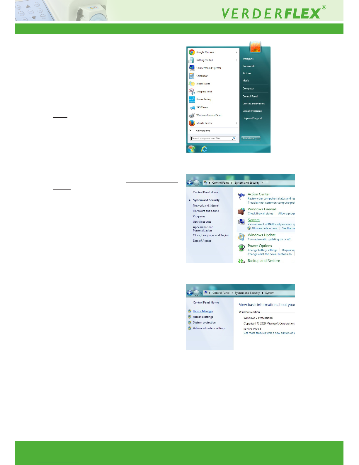
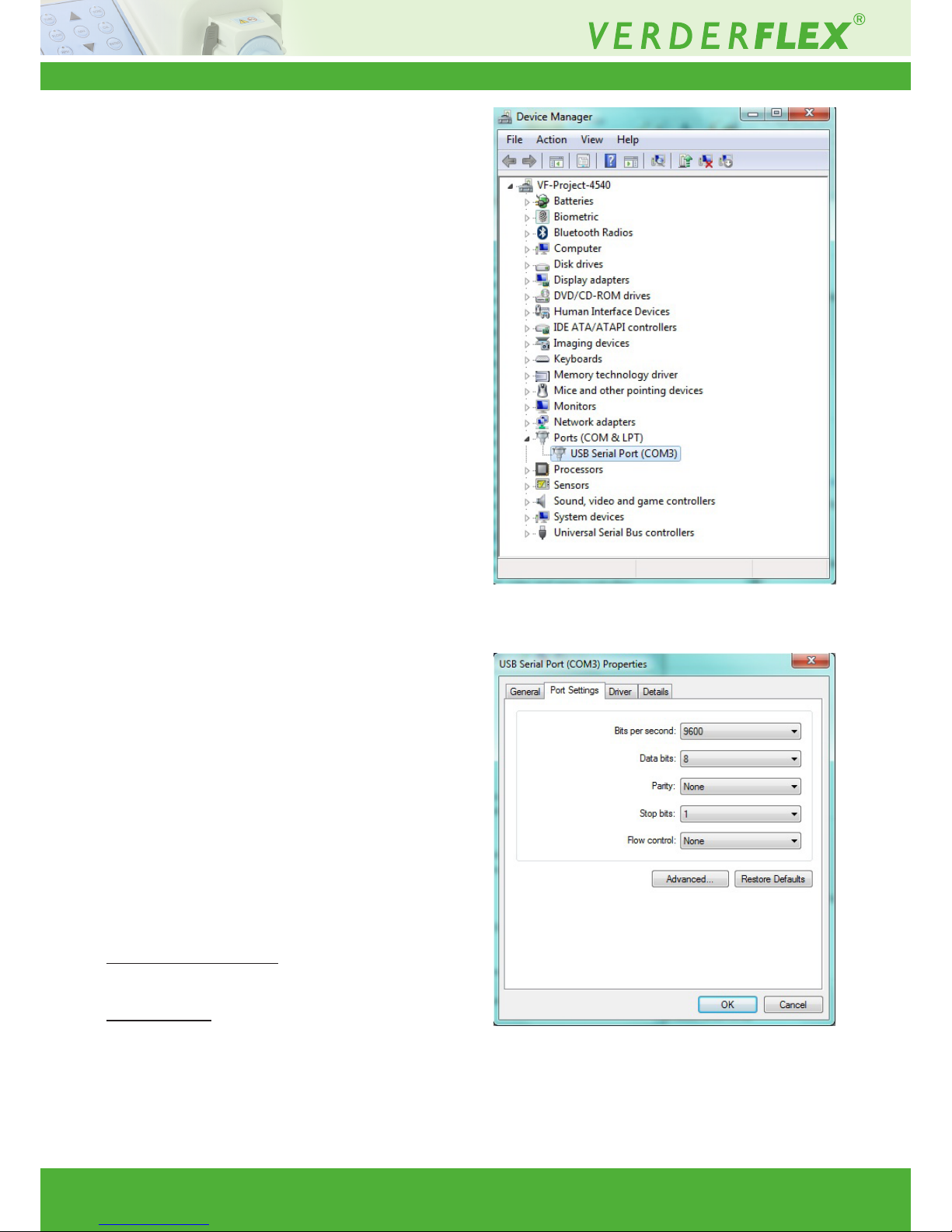
“Device Manager” and scroll down to “Ports
(COM & LPT)”. If the drivers have installed successfully,
you will see “USB Serial Port (COM xx)” (refer g.12).
Where xx = the com port number that the computer
has assigned to the device. Make a note of this
number. Click open “USB serial port” to access the
properties dialogue. Click on the “Port settings” tab.
Ensure that: a) bits per second =9600
b) Data Bits = 8
c) Parity = None
d) Stop bits =1
e) Flow control = None.
6. The folder on the disc supplied has a folder called
“Vantage 3000 software” which contains 4 les: a) PCpumpreadme.docx (Instruction le)
b) PCpump.exe(Application)
c) PCpump.ini (Conguration setting)
d) PC pump Serial interface.doc (Communication
Protocol)
7. Copy PCpump.exe to a directory of your choice.
8. Copy PCpump.ini to C:\WINDOWS. (This le must
reside in the Windows root directory)
9. Click on the le PCpump.ini in your Windows root
directory and edit the line “Port=xx” where xx = the
port number you recorded earlier. E.g. Port=04.
Save the edited le.
Figure 11 Opening the Control Panel
Figure 12 Opening “System Settings”
Figure 13 Opening “Device Manager”
Page 32
Vantage 3000 P Version 3.4v-01/2019
32 | Page32 | Page
10. If you are using an RS232 port on your computer
to communicate with the pump you must also copy
PCPUMP.ini to your windows root directory. In this case,
the line Port=xx in PCPUMP.ini is not important or
necessary.
11. With the USB/RS232 converter plugged into your
computer run PCpump.exe. The program window
should now appear. If the window appears repeatedly
on screen, then the USB/RS232 converter has not
installed correctly.
12. Connect a Null Modem serial cable between the
USB/RS232 converter and the pump’s RS232 DB9
socket. (it must be a Null modem cable not a standard
“pin to pin” serial comm’s cable)
13. The pump can now be controlled by your PC. Consult
the Vantage 3000 Operation Manual for details on
how to use this software utility.
PC pump Serial interface.doc contains information
for the control of the pump using ASCII code
character strings. (Communications protocol)
Dated 01/09/2013
Figure 14 Opening “ Port Settings”
Figure 15 Opening “USB Serial Port Settings”
Page 33

Vantage 3000 P Version 3.4v-01/2019
33 | Page
13 List of Figures and Tables
13.1 List of Figures
Figure 1 Tamper Proof Lable 6
Figure 2 25 way ‘D’ Type Connector (Remote
Control Lead P/N: AU E1973) 8.17
Figure 3 IP66 Computer Control 11.2
Figure 4 Back Plate – Vantage 3000 P 12.2
Figure 5 Back Plate – Vantage 3000 P 12.2
Figure 6 25 Way ‘D’ Type Connector 12.4
Figure 7 Connecting the Footswitch 12.5
Figure 8 Connecting Variable Voltage/Current Source 12.6
Figure 9 25 Way ‘D’ Type Connector 12.7
Figure 10 Connecting the Footswitch 12.7.2
Figure 11 Opening the Control Panel 12.7.3
Figure 12 Opening “System Settings” 12.7.3
Figure 13 Opening “Device Manager” 12.7.3
Figure 14 Opening “Port Settings” 12.7.3
Figure 15 Opening “USB Serial Port Settings” 12.7.3
13.2 List of Tables
Table 1 Keypad Keys and Symbols 1
Table 2 Keypad Key Combinations 1
Table 3 Vantage 3000 P Pump Head Options 7.1
Table 4 Installing the Tube 7.2.2
Table 5 Replacing Pump Head – EZ Head 7.2.3
Table 6 Stacking – EZ Head 7.2.4
Table 7 Installing Tube – S10 Head 7.3.1
Table 8 Installing Tube – R3i Head 7.4.2
Table 9 Replacing the Rotor – R3i Head 7.4.3
Table 10 Analogue /Digital Remote Interface 8.17
Table 11 Models & Control Features Available 12.3
Table 12 Analogue/Digital Connector Pins 12.4
Table 13 Pin Function & Connection 12.5.1
Table 14 Pin Connection for Analogue Control
(refer table 2 for pin description) 12.6.1
Table 15 Digital Connector Pins 12.7.2
Table 16 Declaration of Conformity 14
Table 17 Specication Ratings 15.1
33 | Page
Page 34
Vantage 3000 P Version 3.4v-01/2019
34 | Page
Table 16 Declaration of Conformity
EC declaration of conformity according to machine directive, appendix II A
We,
VERDER Ltd., Unit 3 California Drive, Castleford
hereby declare that the following machine adheres to the relevant EC directives detailed below
Designation Vantage 3000 P EZ
Vantage 3000 P S10
Vantage 3000 P R3i
EC directives:
• Machine Directive (2006/42/EC)
• Low-voltage directive (2014/35/EU)
• EMC directive (2014/30/EU)
Applicable harmonized norms:
• EN ISO 12100: 2010
Manufacturer VERDER Ltd.
Unit 3 California Drive
Castleford
WF10 5QH
UK
Date: 01/ 01/ 2019
Company stamp / signature:
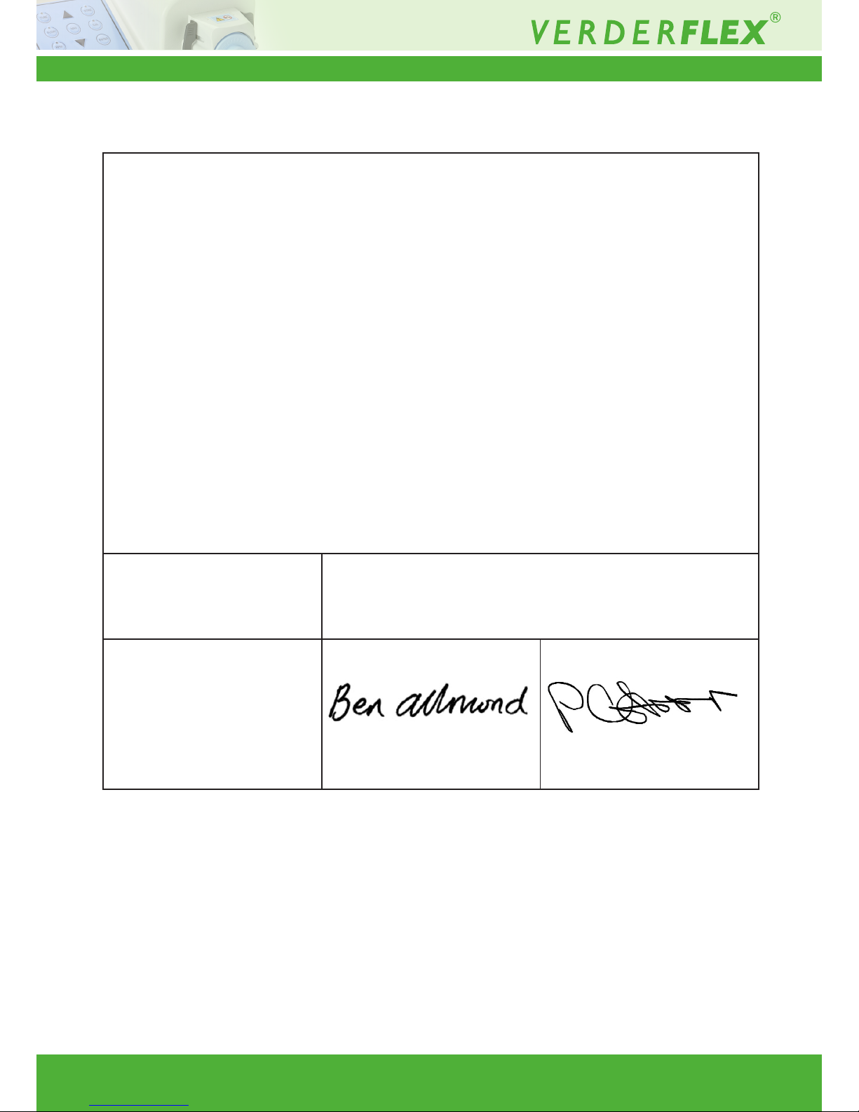
Ben Allmond
Head of Development/Construction
Company stamp / signature:
Paul Storr
Head of Quality
14 Declaration of Conformity
Page 35
Vantage 3000 P Version 3.4v-01/2019
35 | Page
15 Appendix
Pump Specications
15.1 Specication Ratings
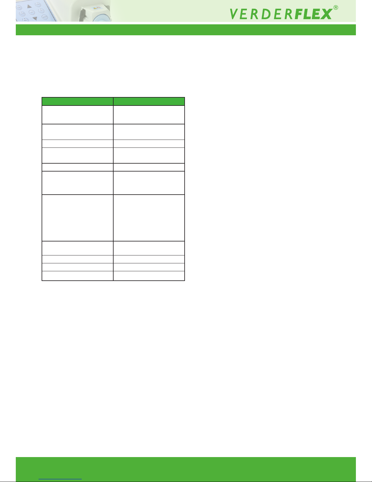
Size Value
Operating temperature +5 °C t o + 40 °C
(41°F to 104 °F)
Storage temperature -4 0 °C to + 70 ° C
(40°F to 158 °F)
Humidity (non-condensing) long—term ≤ 80 %
Maximum altitude Setup height above sea level ≤
2000 m (6560 ft)
Power consumption <230 W
Supply voltage 100-240 VAC
50/60 Hz
<230 W
Maximum voltage uctuation +/-10% of nominal voltage. A
well regulated electrical mains
supply is required along with
cable connections conforming
to the best practice of noise
immunity
Installation category
(overvoltage category)
II
Pollution degree 2
IP IP66 to BS EN 60529
dB rating
<70dB(A) @ 1.0m
*
*
Sound pressure level is measured by the responsible body at both
operators position in normal use and at whatever point 1.0m from the
enclosure of the equipment that has the highest sound pressure rating.
Table 1 Specication Ratings
 Loading...