

Page 1
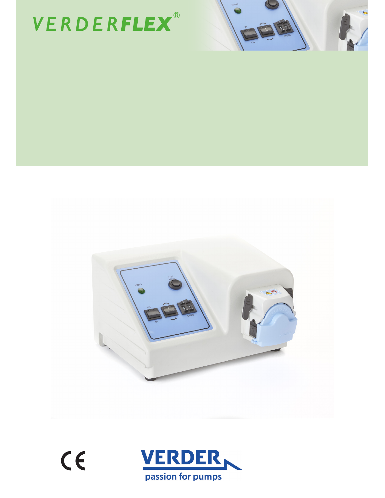
Peristaltic Cased Tube Pumps
Operating Manual Verderex Vantage 3000 B
EZ
Version 1.1v-01/2019
Print-No. 01
Page 2

Vantage 3000 B EZ Version 1.1v-01/2019
2 | Page
Version 1.1v-01/2019
Print-No. 01
Vantage 3000 B EZ
The information in this document is essential for the safe operation and servicing of
Verderex Vantage 3000 pumps. This document must be read and understood thoroughly prior to
installation of unit, electrical connection and commissioning.
Page 3

Vantage 3000 B EZ Version 1.1v-01/2019
3 | Page
Table of Contents
1 About this Document
1.1 Key Features
2 Warranty
3 Pump Returns
4 ‘EC’ Declaration
5 Safety
5.1 Intended Use
5.2 Prevention of Obvious Misuse
6 Maintenance
7 Installation
7.1 Installing the Tube
7.2 Replacing the Pump Head
8 Operating the Pump
9 Declaration of Conformity
10 Appendix - Pump Specications
Page 4

Vantage 3000 B EZ Version 1.1v-01/2019
4 | Page
1 About the Product
The Vantage 3000
©
range of pumps deliver highly
accurate and repeatable ow rates with a quick and
easy setup. Vantage 3000 B EZ is a manual control,
easy tube load pump with a stackable pump head
and requires low maintenance.
1.1 Key Features
- Variable ow peristaltic pump
- Low maintenance replaceable brush motor
- Clockwise and anti-clockwise rotation
- Self priming
- Easy tube load pump head for quick tube change
- Stackable head options
2 Warranty
The manufacturer does not accept any liability for
damage resulting from disregard of this documentation.
This product is guaranteed to be free from defects
in material or workmanship for a period of 24 months
from date of purchase, excluding consumable items
such as cartridges, tubing or rollers. Products out
of guarantee period will be repaired for a nominal charge.
3 Pump Returns
All returned pumps must be decontaminated before
being returned. The Decontamination Certicate
is separately requested and must be returned before
or with the pump delivery. For your protection, items
returned must be carefully packed to prevent
damage in transit and insured against loss.
4 ‘EC’ Declaration
The Vantage 3000 B range, complies with EMC 2014/
30/ EU as well as Machine Directive 2006/42/EC.
Installation of this pump into other equipment must
be in accordance with relevant Directives/Standards
and be carried out by a suitably competent person.
5 Safety
The manufacturer does not accept any liability for
damage resulting from disregard of this documentation.
5.1 Intended Use
• Only use the pump to handle compatible uids
as recommended by the manufacturer.
• Adhere to the operating limits.
• Consult the manufacturer regarding any other use
of the pump.
5.2 Prevention of Obvious Misuse
• Note the operating limits of the pump with regard
to temperature, pressure, ow rate and motor speed.
• Do not operate the pump while the inlet/outlet valve
is closed.
• Only install the pump as recommended in this manual.
For example, the following are not allowed:
– Installing the pump without proper support.
– Installation in the immediate vicinity of extreme
hot or cold sources.
• Do not use in conjunction with life support equipment
• Do not connect pump to the human body
Risk of electrocution!
u Make sure that the electrical information on the
rating plate agrees with the power supply.
u Isolate the main supply before replacing the tube
/cartridge
u Isolate the main supply before removing the
enclosure cover
DANGER
Page 5

Vantage 3000 B EZ Version 1.1v-01/2019
5 | Page
6 Maintenance
Motor and Gearbox are lubricated for life and should
not require attention. Rotor rollers are self-lubricated.
Pump tubing will not last forever; establish suitable
tube replacement schedule to prevent inconvenient
tube failure
7 Installation
Vantage 3000© pump head has the advantage of
quick and easy tube change. Depending on the
application and requirement the tubes can be
replaced or sterilised with a very short lead time
- Pump should be installed by suitably qualied
personnel
- Pump should be sited on stable horizontal surface
- Allow free ow of air around pump
- Tube should not be allowed to kink.
Page 6
Vantage 3000 B EZ Version 1.1v-01/2019
6 | Page
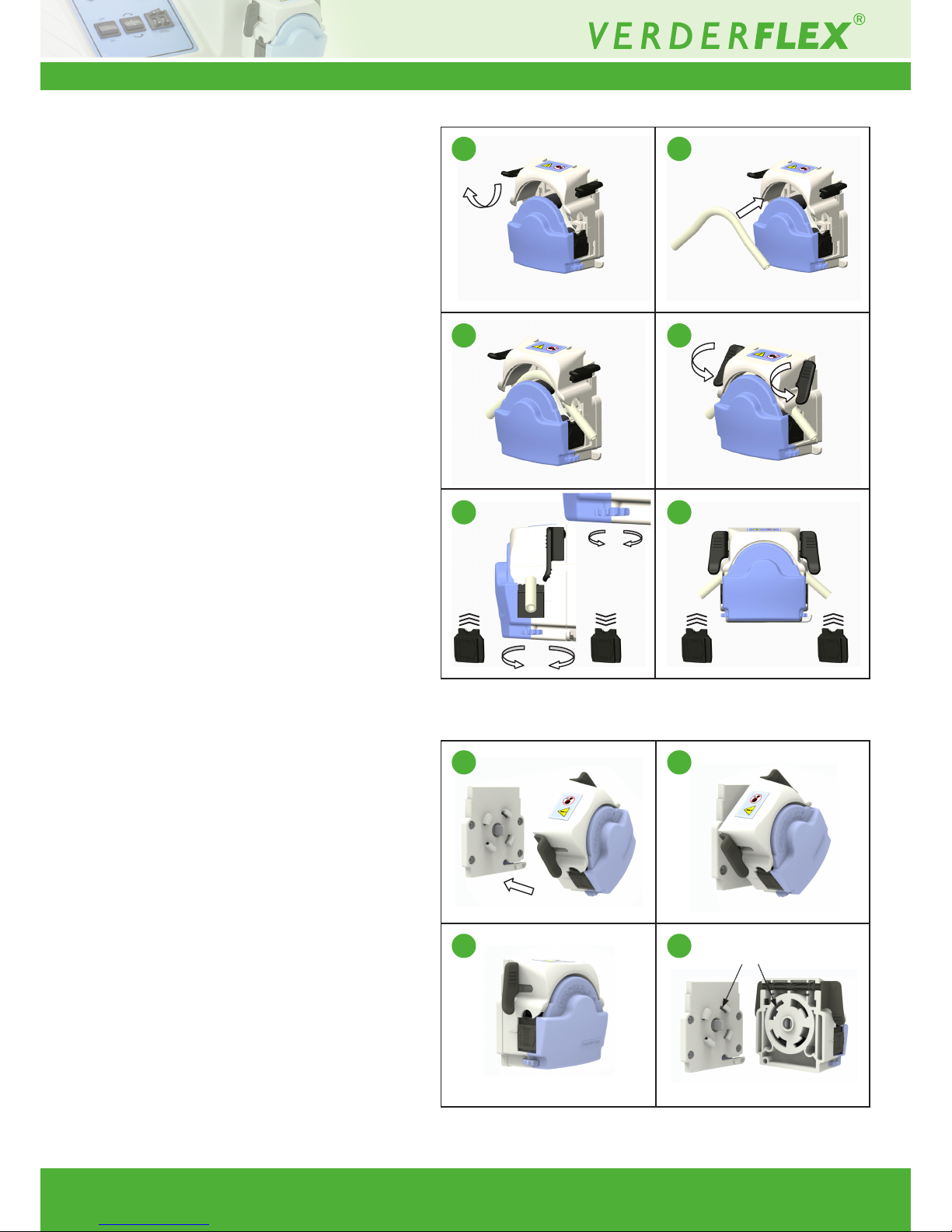
7.1 Installing the Tube
1. Flip the lugs on both sides of the pump head
to lift the top section
2. Once the head is lifted as shown in gure,
insert the tube over the rollers.
3. Flip the lugs on both sides of the pump head
to lock the top section down.
- Adjust the tube clamp to hold the tube
in place and avoid slip
- Adjust the tube clamp on both sides of
the pump head to the tube diameter.
- If a tube slip is observed, tighten the tension
on the clamps
- Alternately, if a reduced ow is observed,
reduce he clamp tension.
7.2 Replacing the Pump Head
1. Offer pump head to backplate at angle
locating drive shaft and rotor shaft
with pump head at approx 45° to vertical,
locating backplate lugs in housing.
2. Push and twist until location lever clicks
into position.
3. Remove by depressing location lever and
twisting pump head counter clockwise 45°.
Table 1 Replacing the Pump Head
Table 2 Replacing Pump Head – EZ Head
Location lugs
1
1
5
2
2
6
3
3
4
4
Page 7
Vantage 3000 B EZ Version 1.1v-01/2019
7 | Page
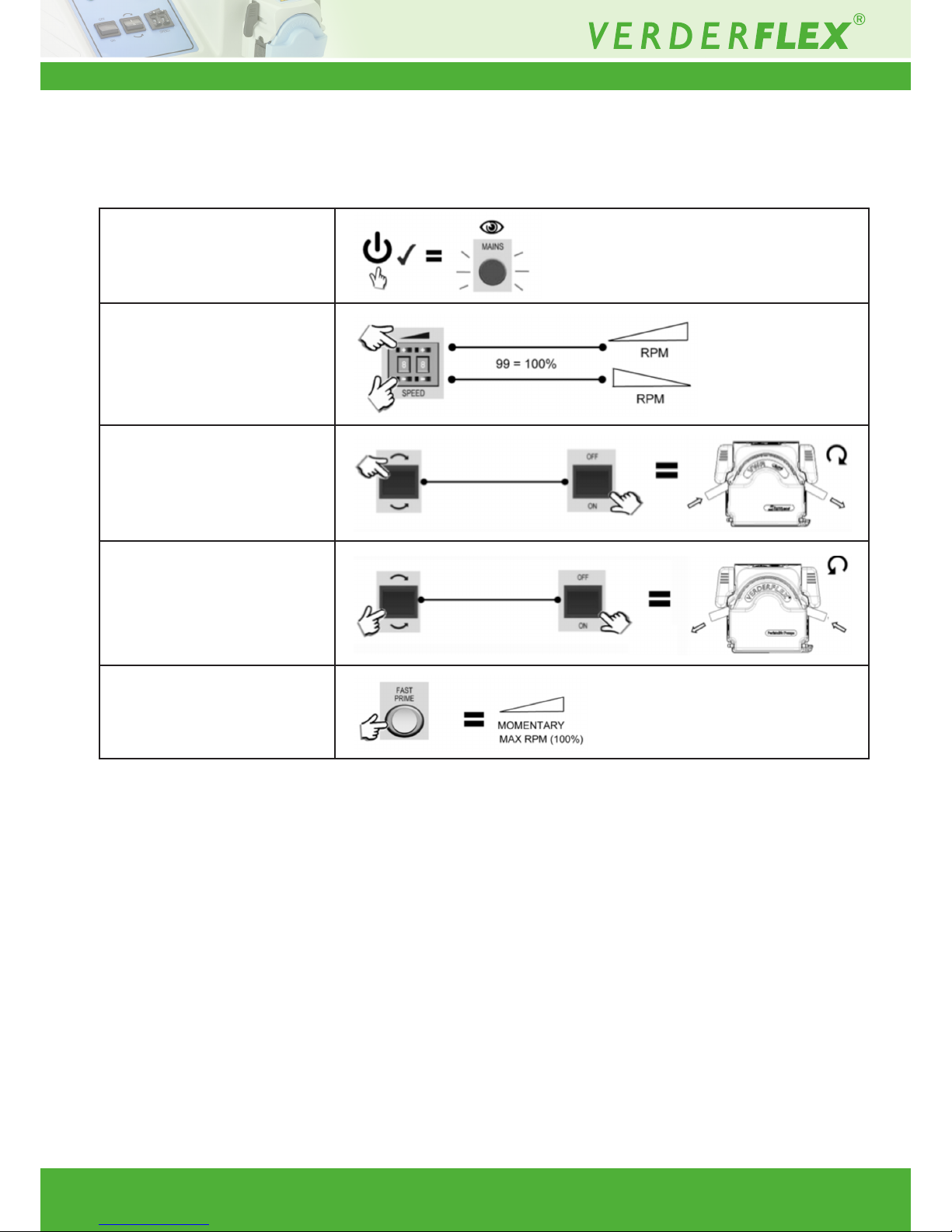
8 Operating the Pump
1. Switch on the main
power supply
2. Set the dosing rpm
3. For clockwise rotation,
set to Clockwise and
switch on the rotor
4. For Counter clockwise
rotation, set to Counter
clockwise and switch on
the rotor
5. Press fast prime for
momentary maximum
speed.
Table 3 Operating the Pump
Page 8
Vantage 3000 B EZ Version 1.1v-01/2019
8 | Page
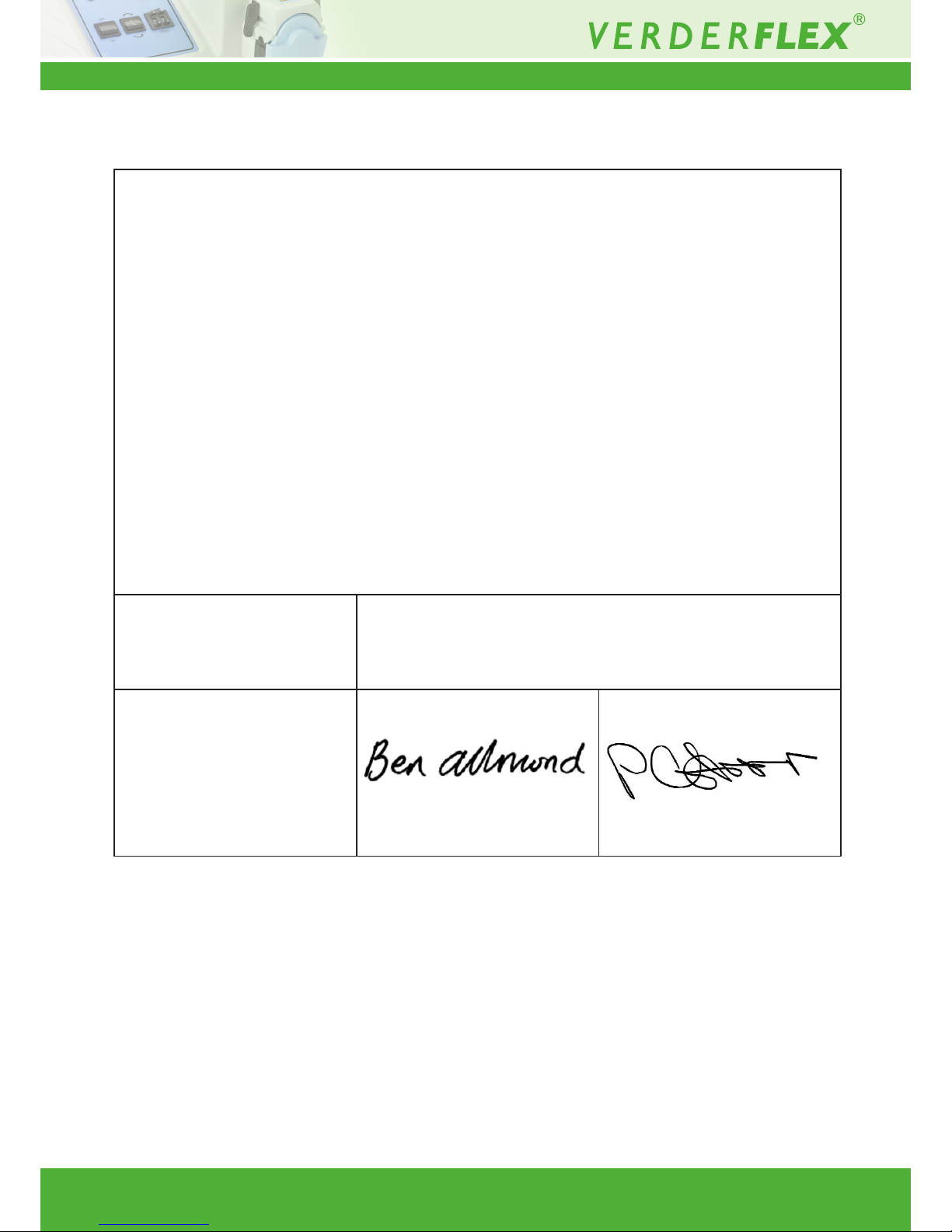
Table 4 Declaration of Conformity
EC declaration of conformity according to machine directive, appendix II A
We,
VERDER Ltd., Unit 3 California Drive, Castleford
hereby declare that the following machine adheres to the relevant EC directives detailed below
Designation Vantage 3000 B EZ
EC directives:
• Machine Directive (2006/42/EC)
• Low-voltage directive (2014/35/EU)
• EMC directive (2014/30/EU)
Applicable harmonized norms:
• EN ISO 12100: 2010
Manufacturer VERDER Ltd.
Unit 3 California Drive
Castleford
WF10 5QH
UK
Date: 01/ 01/ 2019
Company stamp / signature:
Ben Allmond
Head of Development/Construction
Company stamp / signature:
Paul Storr
Head of Quality
9 Declaration of Conformity
Page 9
Vantage 3000 B EZ Version 1.1v-01/2019
9 | Page
10 Appendix
Pump Specications
10.1 Specication Ratings
Size Value
Operating temperature +5 °C to +4 0 °C
(41°F to 104 °F)
Storage temperature -4 0 ° C to + 7 0 °C
(40°F to 158 °F)
Humidity (non-condensing) long—term ≤ 80 %
Maximum altitude Setup height above sea level ≤
2000 m (6560 ft)
Power consumption <230 W
Supply voltage 100-240 VAC
50/60 Hz
<230 W
Maximum voltage uctuation +/-10% of nominal voltage. A
well regulated electrical mains
supply is required along with
cable connections conforming
to the best practice of noise
immunity
Installation category
(overvoltage category)
II
Pollution degree 2
IP IP66 to BS EN 60529
dB rating
<70dB(A) @ 1.0m
*
*
Sound pressure level is measured by the responsible body at both
operators position in normal use and at whatever point 1.0m from the
enclosure of the equipment that has the highest sound pressure rating.
Table 1 Specication Ratings
 Loading...