

Page 1
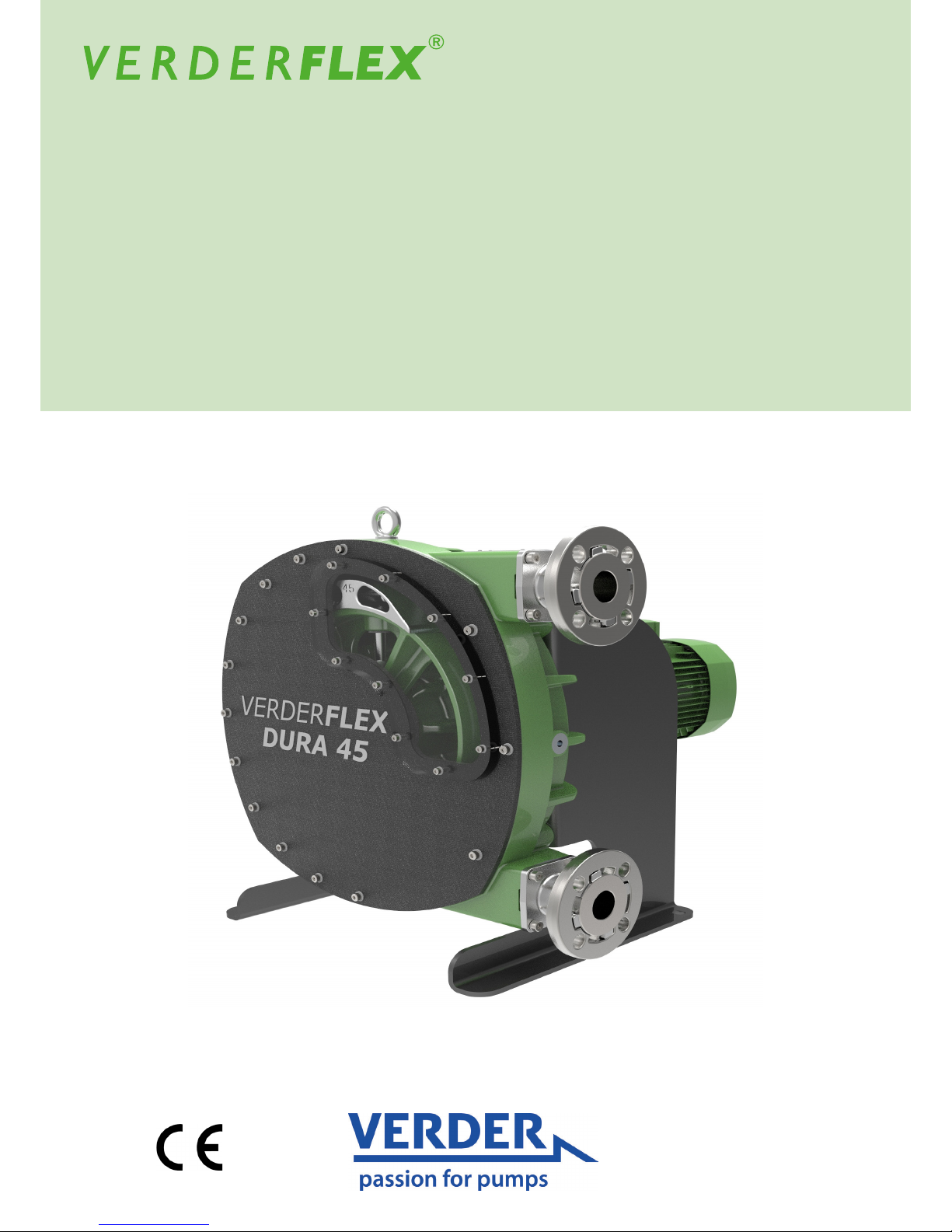
Peristaltic Hose Pump
Operating Manual Dura 45
Version 3.1v-07/2016
Print-No. 01
Page 2

Dura 45 3.1v-07/2016
Version 3.1v-07/2016
Print-No. 01
2 | Page
Dura 45
The information in this document is essential for the safe operation and servicing of Verderex®
pumps. This document must be read and understood thoroughly prior to installation of unit,
electrical connection and commissioning.
Page 3

Dura 45 3.1v-07/2016
1. About this document
1.1 Target groups
1.2 Warnings and symbols
2. Safety
2.1 Intended use
2.2 General safety instructions
2.2.1 Product safety
2.2.2 Obligation of the operating company
2.2.3 Obligation of personnel
2.3 Specic hazards
2.3.1 Hazardous pumped liquids
2.3.2 Lubricants
2.3.3 Sharp edges
3. Layout and function
3.1 Design details
3.2 Labelling
3.2.1 Name Plate
3.3 Layout
3.4 Bearings and Lubrication
4. Transport, storage and disposal
4.1 Transport
4.1.1 Unpacking and inspection on delivery
4.1.2 Lifting
4.2 Treatment for storage
4.3 Interim storage before installation
4.4 Disposal
5. Installation and connection
5.1 Preparing for installation
5.1.1 Checking the ambient conditions
5.1.2 Preparing the installation site
5.1.3 Preparing the foundation and surface
5.2 Installation at site
5.3 Planning the pipes
5.3.1 Specifying supports and ange connections
5.3.2 Specifying nominal diameters
5.3.3 Specifying pipe lengths
5.3.4 Optimizing cross-section of pipe work
5.3.5 Providing safety and control devices
(recommended)
5.4 Shimming
5.5 Electrical connection
5.5.1 Installing motor and gearbox (where not supplied)
5.5.2 Installing motor gearbox on bare-shaft pump
5.5.3 Connecting to power supply
5.6 Installing the hose
5.6.1 Inserting the hose
5.6.2 Fitting the port ange
5.6.3 Filling the pump with lubricant
5.6.4 Fitting the inspection window
5.7 Connecting the pipes
5.7.1 Installing the piping
6. Operation
6.1 Pre-commissioning the pump
6.1.1 Checking the direction of rotation
with dry pump
6.1.2 Starting the pump
6.1.3 Switching off
6.2 Operation
6.2.1 Switching on
6.2.2 Switching off (Refer to -> 6.1.3)
6.3 Shutting down the pump
6.4 Start-up following a shutdown period
6.5 Operating the stand-by pump
7. Maintenance
7.1 Inspections
7.2 Maintenance
7.2.1 Cleaning the pump
7.2.2 Maintenance schedule
7.3 Repairs
7.3.1 Preparations for dismounting
7.3.2 Returning the pump to the manufacturer
7.3.3 Rebuild / Repair
7.3.4 Re-alignment of Rotor after a stall
7.4 Hose change
7.4.1 Dismounting the hose
7.4.2 Re-installing the hose, port anges, lubricant
rell and tting the inspection window
7.5 Ordering spare parts
8. Storing pumps and hoses
8.1.1 Pre-Storage Actions
8.1.2 Cleaning Protocol for hoses
8.1.3 Storage Conditions
9. Troubleshooting
9.1 Pump malfunctions
10. Appendix
10.1 Technical Specications
10.1.1 Pump Specications
10.1.2 Ambient conditions
10.1.3 Tightening torques
10.1.4 Preservatives
10.1.5 Cleaning agents (After hose is removed)
10.1.6 Lubricants
10.1.7 Shimming
10.1.8 Rotor setting distance
11. List of Figures and Tables
11.1 List of gures
11.2 List of tables
12. Declaration of conformity according
to EC Machine Directive
Table of contents
3 | Page
Page 4
Dura 45 3.1v-07/2016
4 | Page
Verderex Peristaltic pump, Dura 45, has been developed according to the latest technology and
subject to continuous quality control. These operating instructions are intended to facilitate familiarization with
the pump and its designated use. The relevant information will act as a guideline for you in operating the pump;
alternative courses of action are also described should you be unable, for any reason, to follow those
procedures initially given. You are advised to follow these guidelines to achieve maximum efciency.
These operating instructions Do not take into account local regulations; the operator must ensure that such
regulations are strictly observed by all, including the personnel called in for installation.
1. About this document
1.1 Target groups
Operating company
Qualied personnel, tter
Table 1 Target groups and their duties
Read, observe and follow this manual and the other applicable
documents, especially all safety instructions and warnings.
Symbol
Table 3 Symbols and their meaning
Meaning
Safety warning sign in accordance with DIN 4844 - W9
Take note of all information highlighted by the safety warning sign
and follow the instructions to avoid injury or death.
Instruction
Multiple-step instructions
1., 2.,
Precondition
Cross-reference
g
Information, recommendation
1.2 Warnings and symbols
Warning
Immediate acute risk
Potential acute risk
Potential hazardous situation
Potential hazardous situation
Death, serious bodily harm
Death, serious bodily harm
Minor bodily harm
Material damage
Table 2 Warnings and consequences of disregarding them
Risk Level Consequences of disregard
DANGER
WARNING
CAUTION
NOTE
Keep this manual available at the operation site of the equipment,
also available for later reference.
Ensure that personnel read and follow the instructions in this
manual and the other applicable documents, especially all safety
instructions and warnings.
Observe any additional rules and regulations referring to the system.
Target groups Duty
Page 5

Dura 45 3.1v-07/2016
5 | Page
2. Safety
The manufacturer does not accept any liability
for damage resulting from disregard of this
documentation.
2.1 Intended use
Only use the pump to handle compatible uids as
recommended by the manufacturer
(g 10.1 Technical specications).
Adhere to the operating limits.
Consult the manufacturer regarding any other use
of the pump.
Pumps delivered without a motor must be tted
with a motor in accordance with the provisions of
EC Machine Directive 2006/42/EC.
Prevention of obvious misuse (examples)
Note the operating limits of the pump with regard to
temperature, pressure, ow rate and motor speed
(g 10.1 Technical specications).
Do not operate the pump while the inlet/outlet valve
is closed.
Only install the pump as recommended in this manual.
For example, the following are not allowed:
– Installing the pump without proper support.
– Installation in the immediate vicinity of extreme hot
or cold sources.
2.2 General safety instructions
Observe the following regulations before carrying
out any work.
2.2.1 Product safety
These operating instructions contain fundamental
information which must be complied with during
installation, operation and maintenance. Therefore
this operating manual must be read and
understood both by the installing personnel and
the responsible trained personnel / operators prior
to installation and commissioning, and it must
always be kept easily accessible within the
operating premises of the machine.
Not only must the general safety instructions laid
down in this chapter on “Safety” be complied with,
but also the safety instructions outlined under
specic headings.
Operate the pump only if the pumping unit and all
associated systems are in good functional
condition.
Only use the pumping system as intended, fully
aware of safety and risk factors involved,
and in adherence to the instructions in this manual.
Keep this manual and all other applicable documents
complete, legible and accessible to personnel at all
times.
Refrain from any procedure or action that would pose
a risk to personnel or third parties.
In the event of any safety-relevant faults, shut down the
pump immediately and have the malfunction
corrected by qualied personnel.
The installation of the pump, associated pipe work and
electrical ttings must comply with the requirements
of installation given in this manual and any local
national or regional health and safety regulations.
2.2.2 Obligation of the operating company
Safety-conscious operation
Ensure that the following safety aspects are observed
and monitored:
– Adherence to intended use
– Statutory or other safety and accident-prevention
regulations
– Safety regulations governing the handling of
hazardous substances if applicable
– Applicable standards and guidelines in the country
where the pump is operated
Make personal protective equipment available
pertinent to operation of the pump; as required.
Qualied personnel
Ensure that all personnel tasked with work on the pump
have read and understood this manual and all other
applicable documents, including the safety,
maintenance and repair information, prior to use or
installation of the pump.
Organize responsibilties, areas of competence and
the supervision of personnel.
Have all work carried out by specialist technicians
only.
Ensure that trainee personnel are under the
supervision of specialist technicians, at all times, when
working on the pumping system.
Safety equipment
Provide the following safety equipment and verify its
functionality:
– For hot, cold and moving parts: safety guarding
should be provided by the operating company.
– For potential build up of electrostatic charge:
ensure appropriate grounding if and when
required.
Page 6
Dura 45 3.1v-07/2016
6 | Page
2.3.3 Sharp edges
Pump parts, such as the shims, can be sharp
– Use protective gloves when carrying out any
work on the pump
3. Layout and function
Peristaltic hose pump, Verderex Dura, is simple by
design in its construction and operation. The medium
to be pumped does not come into contact with any
moving parts and is totally contained within a robust,
heavy-duty hose, which consists of an inner layer, two
– six reinforcement layers and an outer layer. A rotor
passes along the length of the hose, compressing it.
This motion forces the contents of the hose directly in
front of the rotor to move forward along the length of
the hose in a ‘positive displacement’, peristaltic
movement. In the wake of the rotor’s compressing
action, the natural elasticity of the polymer reinforced
rubber forces the hose to open and regain its round
prole, creating suction pressure, which recharges the
pump.
3.1 Design details
Verderex Dura is a twin lobe, single rotor,
peristaltic pump with quick-t tapered port ange
design which clamps and seals in one easy movement
to speed hose replacement.
3.2 Labelling
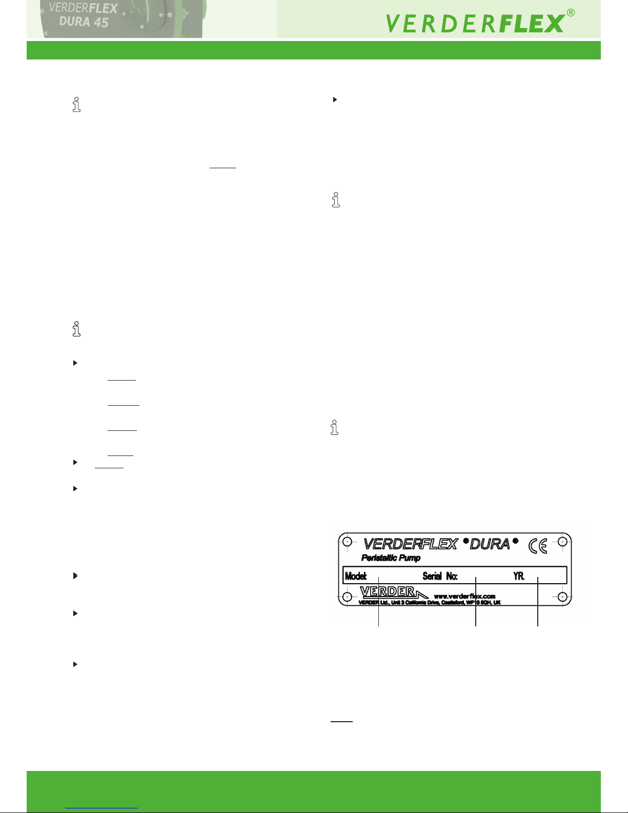
3.2.1 Name Plate
1. 2. 3.
Figure 1: Name plate
1. Pump type
2. Serial number
3. Year of manufacture
Note: When requesting spares, the model and serial
number should always be quoted.
Warranty
The warranty is voided if the customer fails to follow
any and all instructions, warnings and cautions in this
document. Verder has made every effort to illustrate
and describe the product(s) in this document. Such
illustrations and descriptions are, however, for the sole
purpose of identication and Do not express or imply a
warranty that the products are merchantable or t for a
particular purpose, or that the products will necessarily
conform to the illustration or descriptions.
Obtain the manufacturer’s approval prior to carrying
out any modications, repairs or alterations during the
warranty period. Only use genuine parts or parts that
have been approved by the manufacturer.
For further details regarding warranty, please refer
terms and conditions.
2.2.3 Obligation of personnel
It is imperative that the instructions contained in this
manual are complied with by the operating personnel
at all times.
Pump and associated components:
– Do not lean or step on them or use as climbing
aid
– Do not use them to support boards, ramps
or beams
– Do not use them as a xing point for winches
or supports
– Do not de-ice using gas burners or similar tools
Do not remove the safety guarding for hot, cold or
moving parts during operation.
Reinstall the safety equipment on the pump as
required by regulations after any repair / maintenance
work on the pump.
2.3 Specic hazards
2.3.1 Hazardous pumped liquids
Follow the statutory safety regulations when handling
hazardous pumped liquids (e.g. hot, ammable,
poisonous or potentially harmful).
Use appropriate personal protective equipment when
carrying out any work on the pump.
2.3.2 Lubricants
Ensure that the lubricant and pumped liquid are
compatible with each other. This is a precautionary
measure in case of accidental hose burst whereby
the pumped liquid comes in contact with the
lubricant.
(Refer datasheet for lubricant to ensure
compatibility)
Page 7
Dura 45 3.1v-07/2016
7 | Page
3.4 Bearings and Lubrication
Pump: To be lled at installation with appropriate
lubricant if not supplied pre lled. (g10.1.6
Lubricants)
Bearings are sealed units and need no additional
lubricant.
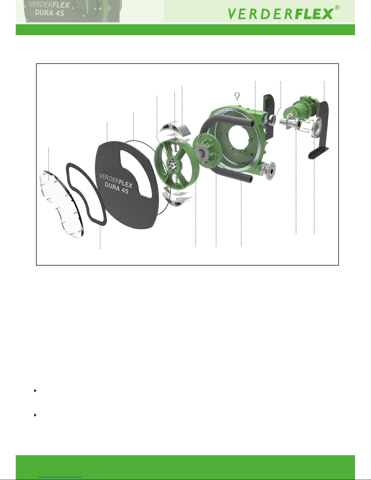
Figure 2 Layout
1 Inspection window 6 Shims 11 Pump casing
2 Inspection window gasket 7 Rotor shoe 12 Clamp ring
3 Front cover 8 Rotor 13 Port ange
4 Front cover o-ring 9 Hose 14 ¼ turn ange
5 Slip bush 10 Bearing housing 15 Mounting frame
3.3 Layout
1
2
3
4
5
6
7
11
8
9
13 14
15
12
10
Page 8
Dura 45 3.1v-07/2016
8 | Page
4. Transport, storage and
disposal
4.1 Transport
Always transport the unit in an upright position and
ensure that the unit is securely attached to the
pallet.
4.1.1 Unpacking and inspection on delivery
1. Unpack the pump/pump unit upon delivery and
inspect it for transport damage.
2. Report any transport damage to the manufacturer/
distributor immediately.
3. Retain the pallet if any further transport is required.
4. Dispose all packaging material according to local
regulations.
4.1.2 Lifting
Death or crushing of limbs can be caused by falling
loads!
1. Use lifting gear appropriate for the total weight to be
transported.
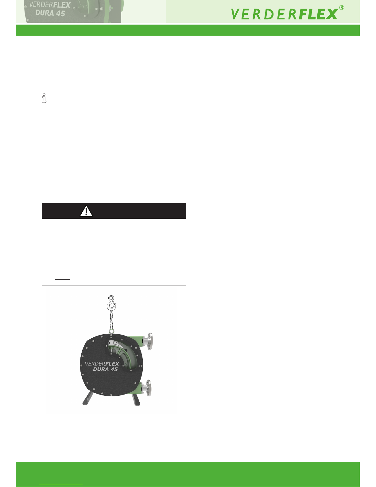
2. Fasten the lifting gear to the lifting eye as shown in the
following illustration.
3. Do not stand under suspended loads.
DANGER
Figure 3 Fastening lifting gear to pump unit
Page 9
Dura 45 3.1v-07/2016
9 | Page
4.2 Treatment for storage
Unpainted steel surfaces should be coated with rust
inhibitor and the unit should be stored in a dry, dust
free environment not exceeding 60°C
Material damage due to inappropriate treatment for
storage!
Treat all internal and external bare metal pump parts
for storage.
– Renew treatment if necessary.
4.3 Interim storage before installation
Material damage due to inappropriate storage!
Treat the pump with preservatives compatible with
pumped media (precaution in case of spillage).
1. Close all openings with blanks, plugs or plastic
covers.
2. Make sure the storage room meets the following
conditions:
– Dry, humidity not to exceed 80%
– Out of direct sunlight
– Frost-free; temperature range 0 to 40°C
– Vibration-free; minimize
– Dust-free; minimize
*Storage information for pumps withdrawn from use is listed in
section 8, Storing pumps and hoses.
4.4 Disposal
With prolonged use, pump parts can get contaminated
by poisonous or radioactive pumped liquids to such an
extent that cleaning may be insufcient.
Risk of poisoning and environmental damage by the
pumped liquid or oil!
Use suitable personal protective equipment when
carrying out any work on the pump.
Prior to disposal of the pump:
– Drain and dispose the lubricant in accordance with
local regulations.
– Collect and dispose of any leaking pumped liquid or
oil in accordance with local regulations.
– Neutralize residues of pumped liquid in
the pump.
Dispose of the pump unit and associated parts in
accordance with statutory regulations.
5. Installation and connection
Material damage due to unauthorized modication
on pump unit!
Do not make any structural modications to the pump
unit or pump casing
Do not carry out any welding work on the pump unit or
pump casing
Material damage caused by ingress!
– Do not remove any protective ange covers until
immediately before connecting the pipes to the
pump
5.1 Preparing for installation
5.1.1 Checking the ambient conditions
1. Make sure that the operating conditions are complied
with (g 10.1.1 Pump specications)
2. Make sure the required ambient conditions are fullled
(g 10.1.2 Ambient conditions)
5.1.2 Preparing the installation site
Ensure the installation site meets the following
conditions:
– Pump is freely accessible from all sides
– Sufcient space is available for the installation/
removal of the pipes and for maintenance and
repair work, especially for the removal and
installation of the hose.
5.1.3 Preparing the foundation and surface
Make sure the foundation and surface meet the
following conditions:
– Level
– Clean (no oil, dust or other impurities)
– Capable of bearing the weight of the pump unit and
all operating forces
– Ensure the pump is stable and cannot tip over
– Concrete foundation: Standard concrete strong
enough to support the pump unit under load.
5.2 Installation at site
1. Lift the pump unit (g 4.1.2 L+ifting)
2. Put the pump unit down at the instillation site.
3. Bolt the pump down; use all 4 holes.
WARNING
NOTE
NOTE
NOTE
NOTE
Page 10
Dura 45 3.1v-07/2016
10 | Page
5.3 Planning the pipes
5.3.1 Specifying supports and ange
connections
1. When planning pipe runs take every possible
operating condition into account:
– Cold/warm medium
– Empty/full
– Unpressurized/pressurized
– Positional change of the anges
2. Ensure that the pipe supports are designed to
accommodate any movement from environmental
or pressure imposed forces.
5.3.2 Specifying nominal diameters
Keep the ow resistance in the pipes as low as possible.
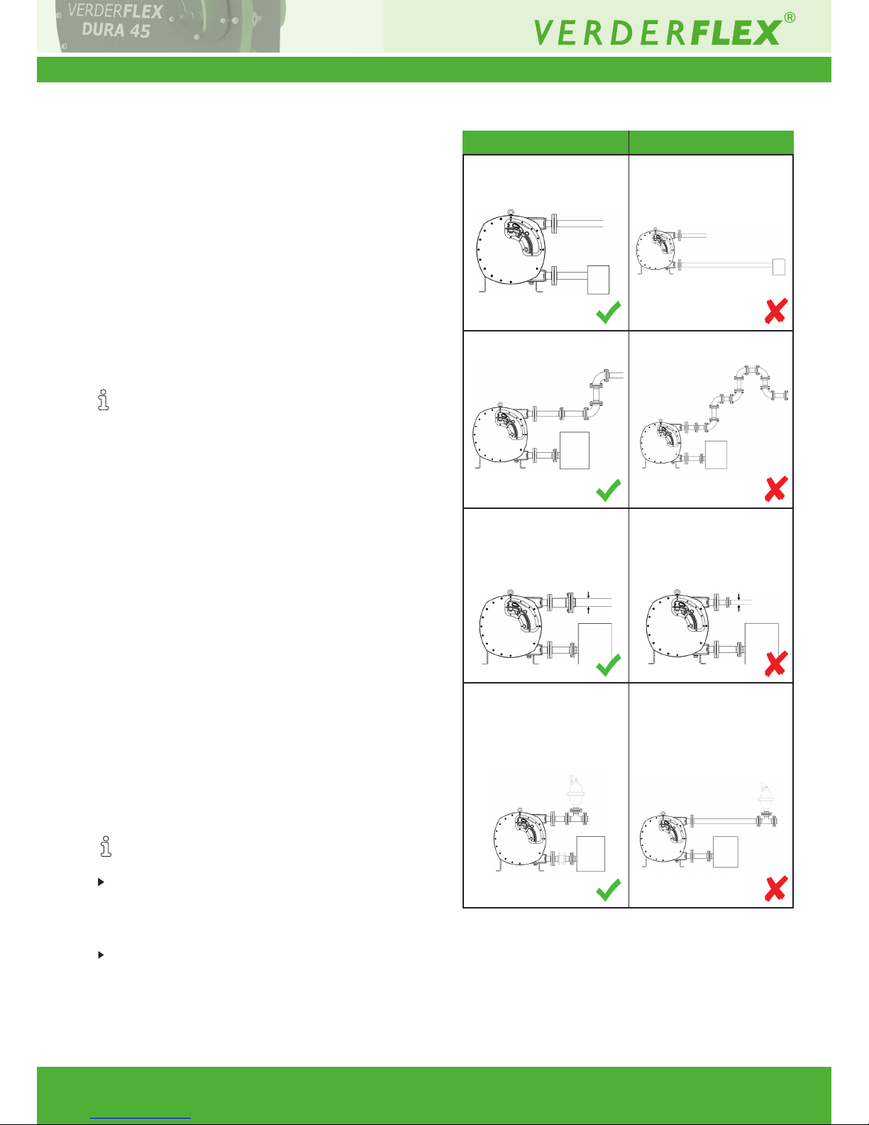
Pipe work immediately connected to both inlet and
outlet port of the pump should be straight runs for at
least 1 meter.
Ensure that nominal pipe diameter is at least 1.5 times
nominal pump-hose diameter to reduce pulsation.
5.3.3 Specifying pipe lengths
1. Keep pipe work as short and direct as possible.
2. To allow easy access when changing hoses, include
a short, removable section adjacent to the port
anges.
5.3.4 Optimizing cross-section of pipe work
1. Avoid bending radii of less than 10r (r-radii of
nominal piping)
.2. Avoid abrupt changes of cross-section along the
piping.
5.3.5 Providing safety and control devices
(recommended)
Making provisions for isolating and shutting off pipes
For maintenance and repair work.
Provide shut-off valves in the suction and discharge
lines.
Allowing safe removal of product
Include drainage taps in suction and discharge lines
at the lowest point.
1. Short pipe run to
suction side
Long pipe run to suction
side
2. Reduced Joints/Bends Multiple Joints/Bends
4. Pulsation damper
connected close
to the pump
Pulsation Damper
Bellows
Pulsation damper
connected away from
pump
10% loss in damper efciency
for every meter
3. Connecting pipe with
diameter 1.5 times pump
hose diameter
Pipe ID 1.5 times hose ID
Connecting pipe with
smaller than pump hose
diameter
Pipe ID < pump hose ID
Table 4 Do’s and Don’ts
Do’s Don’ts
Page 11
Dura 45 3.1v-07/2016
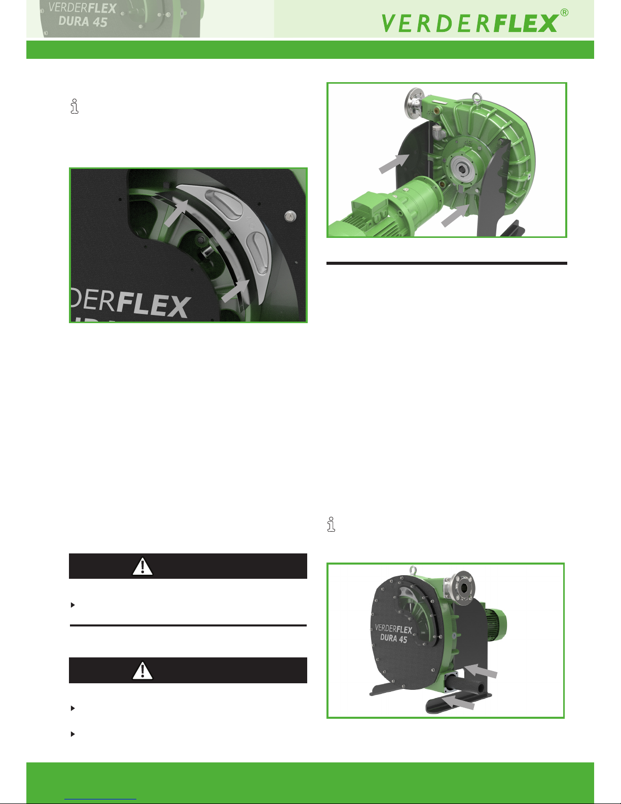
5.4 Shimming
The pump must be shimmed for the required
discharge pressure (g 10.1.7 Shimming).
Normally, shims are factory set and would not require
any user adjustment. But if and when required shims
can be adjusted with the following procedure.
1. Rotate the pump so that a rotor shoe is visible in the
window and then remove the window and gasket.
Leave the bolts on the window for reassembly.
2. Loosen the shoe bolt.
3. Remove any existing shims.
4. Replace with correct number of shims for the required
pressure (g10.1.7 Shimming).
5. Tighten the shoe bolt (g 10.1.3 Tightening torques).
6. Repeat with the other rotor shoe.
7. Ensure the lubricant level is correct.
8. Replace the window and gasket ensuring it is tted
the correct way with the bolts (g 5.5.5 Fitting the
inspection window).
5.5 Electrical connection
Risk to health due to electric shock!
All electrical work must be carried out by qualied
electricians.
5.5.1 Installing motor and gearbox (where not
supplied)
Death or crushing of limbs caused by falling loads!
Use lifting gear appropriate for the total weight to
be transported.
Do not stand under suspended loads.
11 | Page
5.5.2 Installing motor gearbox on bare-shaft
pump
1. Lift motor and gearbox on a sling.
2. Apply anti seize grease to the gearbox shaft.
3. Offer gearbox shaft up to the bearing housing.
4. Align key to the key way.
5. Fit the eight M10 bolts.
6. Use a torque wrench to apply tightening torque
(g10.1.3 Tightening torques).
5.5.3 Connecting to power supply
1. Connect motor to the rated power supply. Ensure the
correct gland is used and that the earth connection
is made and secured.
2. Run the pump slowly to ensure correct rotation.
5.6 Installing the Hose
5.6.1 Inserting the hose
Possible when the motor has been wired up or
alternately it can be done by removing the fan cover
and rotating the shaft.
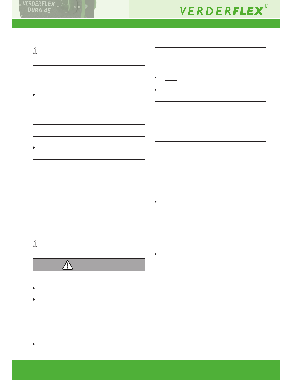
Figure 5 Installing motor gearbox
Figure 4 Shimming
DANGER
DANGER
Figure 6 Inserting Hose
Page 12
Dura 45 3.1v-07/2016
• Add 1/2 a liter of lubricant to the pump housing.
• Lubricate the hose generously with Verderlube /
Verdersil.
• Insert the hose into the lower port.
• Run the pump forward until the hose is fed through
the pump casing and is protruding from the port
ange mounting face by about 30 mm.
– This can be done either by connecting the pump
to a motor that can be run slowly or by manually
rotating the shaft after removing the fan cover.
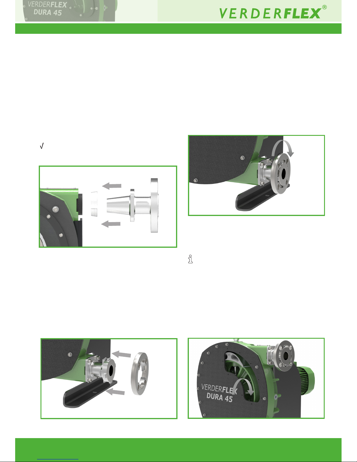
5.6.2 Fitting the port ange
Hose in position and protruding about 30mm on the
inlet side (the side through which the hose had been
inserted)
1. Slide on the clamp ring with the smallest diameter
facing the pump, until the clamp ring is inside
and is ush with the pump housing.
2. Apply some lubricant compatible with the pumped
media to the port ange.
3. Push the port ange-insert into the hose.
4. Install the 4 bolts.
5. Tighten the bolts in a 1–3–4–2 sequence until the
ange is evenly tted, but not completely tightened,
leaving about 10mm slack.
12 | Page
Figure 7 Fitting the port ange-insert
Figure 8 Fitting the port ange
6. Rotate the rotor slowly in a direction to feed the
hose onto the taper.
7. Tighten all 4 bolts fully to clamp the hose and
ensure the hose can be seen through the aperture
in the side of casing formed between the ange and
the casing.
8. Run the pump forward and stop when the hose
protrudes from the other end by about 30mm
9. Repeat the sequence for installing the ange (refer
points 1-6)
10. Fit the ¼ turn ange connector to both ports
5.6.3 Filling the pump with lubricant
The safety data sheets for both Verderlube and
Verdersil are available from the manufacturer for
compatibility check.
• Provide a suitable container to collect spilt lubricant.
• Ensure compatibility of lubricant with the pumped
liquid.
• Fill the pump to the level where uid starts to come
through the lowest bolt hole of the inspection
window (→ 10.1.6 Lubricants).
Figure 9 Bolting down the ange
Figure 10 Filling pump with lubricant
Page 13
Dura 45 3.1v-07/2016
1. Fit M6 cap head bolts with washers into the window.
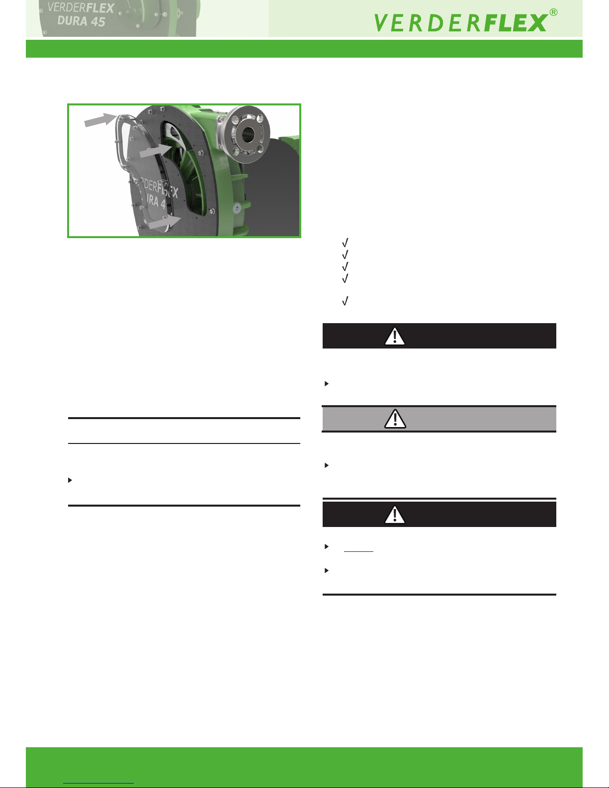
The window is threaded to make bolts captive and
counter-bored on the back face.
2. Mount the gasket on to the bolts.
3. Mount the window unit, with the bolts and gasket, ove
the front cover, aligned as shown in g. 10
4. Nip the bolts down in sequence. Ensure that the bolts
are not over-tightened.
You can see the gasket pressing against the window
as the bolts clamping force takes effect.
5.6.4 Fitting the inspection window
13 | Page
5.7 Connecting the pipes
Contamination of pumped media due to impurities in
the pump!
Care should be taken to avoid ingress of contaminants
into the pumped media.
1. Clean all piping parts and ttings prior to assembly.
2. Ensure that the ange seal do not protrude inwards
occluding the ow path.
3. Remove ange covers on both the suction and
discharge side prior to installation.
5.7.1 Installing the piping
1. Check all fasteners are tightened (g 10.1.3 Tightening
torques)
2. Ensure that the 1/4 turn ange is correctly indexed.
3. Remove the transport and sealing covers from the
pump.
4. Before connecting any piping to the pump: Ensure
that the hose is properly secured by running the pump
dry for 10–20 revolutions in both the directions.
5. Run the pipes in a continuous upward or downward
slope to avoid air pockets
6. Connect the piping
Figure 11 Mounting the inspection window
NOTE
6.1 Pre-commissioning the pump
6.1.1 Checking the direction of rotation with
dry pump
1. Ensure the pump has lubricant in it
2. Switch the motor on and check the direction of
rotation; switch immediately off again.
3. If the direction of rotation is different: swap two of
the phases (*check with electrician)
6.1.2 Starting the pump
Pump set up and connected properly
Motor set up and connected properly
All connections stress-free and sealed
Pump housing lubricant level correct (g 10.1.6
Lubricants).
All safety equipment installed and tested for
functionality
Risk of injury and poisoning due to pumped liquid
spraying out!
Use personal protective equipment when carrying out
any work on the pump.
Risk of injury and poisoning due to hazardous
pumped liquids!
Safely collect any leaking pumped liquid and dispose
of it in accordance with environmental rules and
requirements.
Equipment damage due to excess pressure!
Do not operate the pump with the discharge-side
tting closed.
Operate the pump only inside the tolerances specied
by the manufacturer (g 10.1 Technical specications)
1. Close all drainage taps.
2. Open the suction-side and the discharge-side
ttings.
3. Switch on the motor and make sure it is running
smoothly.
4. Run the pump, ushing with water rst (cold
commissioning) to check for leaks.
5. Verify that neither the pump unit nor the pipe
connections are leaking.
6. Perform a second ush by running the pump, 10–20
revolutions with pumped liquid, to remove residue
and water inside the pump.
DANGER
DANGER
6. Operation
WARNING
Page 14
Dura 45 3.1v-07/2016
14 | Page
6.1.3 Switching off
Risk of dead heading and hose burst due to closed
suction or discharge!
Keep the suction and discharge side ttings opened
till the rotor has come to a complete stop.
Risk of injury due to hot pump parts!
Use personal protective equipment when carrying
out any work on the pump.
Equipment damage due to sediments!
If the pumped liquid crystallizes, polymerizes or
solidies:
– Flush pump
– Make sure that the ushing liquid is compatible
with the pumped liquid.
1. If necessary: Flush and empty the pump.
2. Switch off power to the motor.
3. Close the discharge side tting.
4. Check all tie bolts and tighten them if necessary (only
after putting the pump into service for the rst time).
WARNING
NOTE
NOTE
6.2 Operation
6.2.1 Switching on
Pump pre-commissioned (g6.1)
Pump prepared and lled
Risk of injury due to running pump!
Do not touch the moving parts of a running pump.
Do not carry out any repair/ maintenance work on the
running pump.
Allow the pump to cool down completely before
starting any work on the unit.
Risk of injury and poisoning due to pumped liquid
spraying out!
Use personal protective equipment when carrying
out any work on the pump.
Risk of pulsation when throttling down the suction
ow rate!
Fully open the suction-side tting and DO NOT use
it to adjust the ow as this could damage the hose.
1. Open the suction-side and the discharge-side
ttings.
2. Switch on the motor and make sure it is running
smoothly.
6.2.2 Switching off (Refer to g 6.1.3)
Risk of injury due to hot pump parts!
Use personal protective equipment when carrying out
any work on the pump.
Damage to hose due to sediments!
If the pumped liquid crystallizes, polymerizes or
solidies
– Flush the hose
– Make sure that the ushing liquid is compatible
with the pumped liquid.
DANGER
DANGER
WARNING
NOTE
NOTE
Page 15
Dura 45 3.1v-07/2016
15 | Page
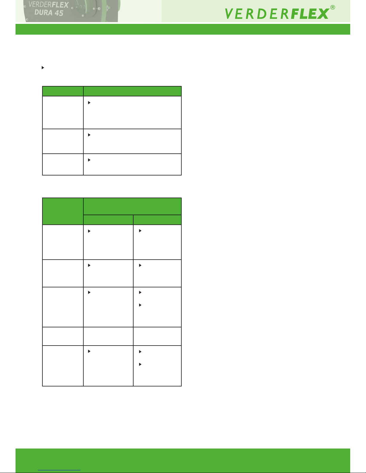
6.3 Shutting down the pump
Take the following measures whenever the pump is
shut down:
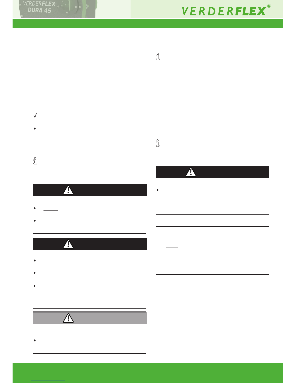
Behaviour of
the pumped
liquid
Duration of shutdown (depending
on process)
Short Long
shut down
...dismounted
...put into
storage
crystallized or
polymerized,
Solids
sedimenting
Solidifying
non-corrosive
Solidifying
corrosive
Liquid,
corrosive
Liquid,
non-corrosive
Flush the
pump.
Heat up or
empty the
pump
Heat up or
empty the
pump
Empty the
pump
-
Flush the
pump,
remove the
hose.
Empty the
pump
Empty the
pump.
Treat the
pump with
preservative.
Empty the
pump.
Treat the
pump with
preservative.
-
Take measures according to the
pumped liquid (g Table 6
Measures depending on the
behaviour of the pumped liquid).
Isolate the motor from its power
supply and secure it against
unauthorized switch-on.
Follow the storage instructions
(g 8 Storage).
Table 5 Measures to be taken if the pump is shut down
Table 6 Measures depending on the behaviour of the
pumped liquid
Pump is Measure
Page 16
Dura 45 3.1v-07/2016
7.1 Inspections
The inspection intervals depend on the pump
operating cycle.
1. Check at appropriate intervals:
– Normal operating conditions unchanged
2. For trouble-free operation, always ensure the
following:
– Lubricant level
– No leaks
– No unusual running noises or vibrations
– Hose in position
7.2 Maintenance
These pumps are generally maintenance free and any
work should normally be limited to inspections and
pump lubricant changes as required; these may be
more frequent in dust and/or hot condition.
Risk of electrocution!
Have all electrical work carried out only by qualied
electricians.
7.2.1 Cleaning the pump
High water pressure or spray water can damage
motors!
Do not clean motors with water or steam jet.
1. Clean large-scale grime from the pump.
2. Rinse the hose carefully to remove chemicals
(follow the cleaning protocol as listed in g 8.1.2
Cleaning protocol for hoses).
6.4 Start-up following a shutdown
period
1. After a prolonged shutdown period, re-commission
the pump as follows:
– Replace the seals.
– Install or change hose (g 7.4 Hose change).
2. Carry out all steps as for the initial start-up (g 6.1 Pre
commissioning the pump).
6.5 Operating the stand-by pump
Stand-by pump is lled with lubricant (g5.6.3 Filling
the pump with lubricant)
Operate the stand-by pump at least once a week to
avoid formation of permanent dents on the hose.
7. Maintenance
Only trained service technicians should be employed
for tting and repair work. Present a pumped medium
certicate (DIN safety data sheet or safety certicate)
when requesting service.
Risk of injury due to running pump or hot parts!
Do not carry out any repair/maintenance work on
a pump in operation.
Allow the pump to cool down completely before
starting any repair work.
Risk of injury due to possible pressure buildup!
Do not carry out any repair/maintenance work on
a pump in operation.
Do not block the breather tube which is designed
for pressure relief.
In the unlikely event of a hose burst which leads to
blockage of the breather tube - safely relieve the
pressure inside the casing before disassembling
the pump .
Risk of injury and poisoning due to hazardous
pumped liquids!
Use protective equipment when carrying out any
work on the pump.
16 | Page
DANGER
DANGER
DANGER
NOTE
WARNING
Page 17

Dura 45 3.1v-07/2016
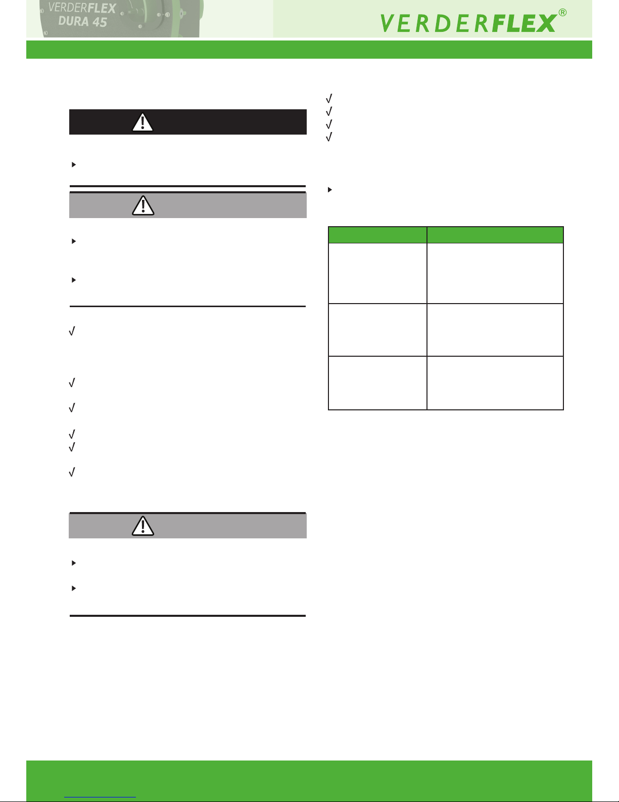
7.2.2 Maintenance schedule
17 | Page
Table 7 Maintenance schedule
Task Frequency Action
Check pump and gearbox for leaks and
damage
Check pump housing lubrication level
Check geared motor unit lubrication
level
Check pump for unusual temperatures
or noise in operation
Replace pump housing lubricant
Replace hose
Check pump housing and rotor
internally
Replace bearing housing
Replace bearing housing seal
– Before pump start up
– Daily visual inspection
– Scheduled intervals during
operation
– Before pump start up
– Daily visual inspection
– Scheduled intervals during
operation
– Before pump start up
– Daily visual inspection
– Scheduled intervals during
operation
– Daily visual inspection
– Scheduled intervals during
operation
– At every hose change or every
six months
– After inspection when required
– After inspection when required
– When ow has dropped by 25% of
nominal value
– When the hose is burst/damaged
– Annually
– On replacing the hose
– After 30,000 running hours
– When damage is suspected
– When damage is suspected
– When leak is detected
Repair leaks and damage before
operating the pump
Replace components as necessary.
Clean up any spillage.
Make sure that lubricant level is
visible in the inspection window
between the lower sill and the
rst pair of bolts.
Do not operate the pump if the level
is too low or too high. Rell lubricant
as required. (g5.6.3 Filling the
pump with Lubricant )
g
Motor instruction manual.
Check pump, gearbox and bearing
housing for damage.
Replace worn components.
Rell lubricant (g5.6.3 Filling the
pump with Lubricant )
Replace hose (g 7.4 Hose change)
Worn and damaged surfaces give rise
to premature hose failure
Replace worn components.
Check bearing play and function.
Check bearing play and function.
Replace worn components.
Page 18
Dura 45 3.1v-07/2016
7.3 Repairs
Risk of death due to electric shock!
Have all electrical work carried out by qualied
electrician only
Risk of injury due to heavy components!
Pay attention to the component weight. Lift and
transport heavy components using suitable lifting
gear.
Set down components safely and secure them against
overturning or rolling away.
7.3.1 Preparations for dismounting
Safely release any pressure build up in the pump
housing. (There may be signicant built up of pressure
in the discharge line or possible suction side
vacuum).
Pump completely emptied, ushed and
decontaminated
Electrical connections disconnected and motor locked
out against being switched on again
Pump cooled down
Auxiliary systems shut down, depressurized and
emptied
Before dismounting the pump, mark the precise
orientation and position of all components before
dismounting them.
Risk of injury while dismounting the pump!
Use protective equipment when carrying out any work
on the pump.
Observe manufacturer’s instructions (e.g. for Motor,
coupling, gearbox).
18 | Page
DANGER
7.3.2 Returning the pump to the manufacturer
Pump unpressurized
Completely emptied and decontaminated.
Pump cooled down
Hose dismounted (g7.4.1 Dismounting the hose)
Obtain prior authorization before repair or return of
the pump.
Enclose a completed document of compliance when
returning pumps or components to the manufacturer
WARNING
WARNING
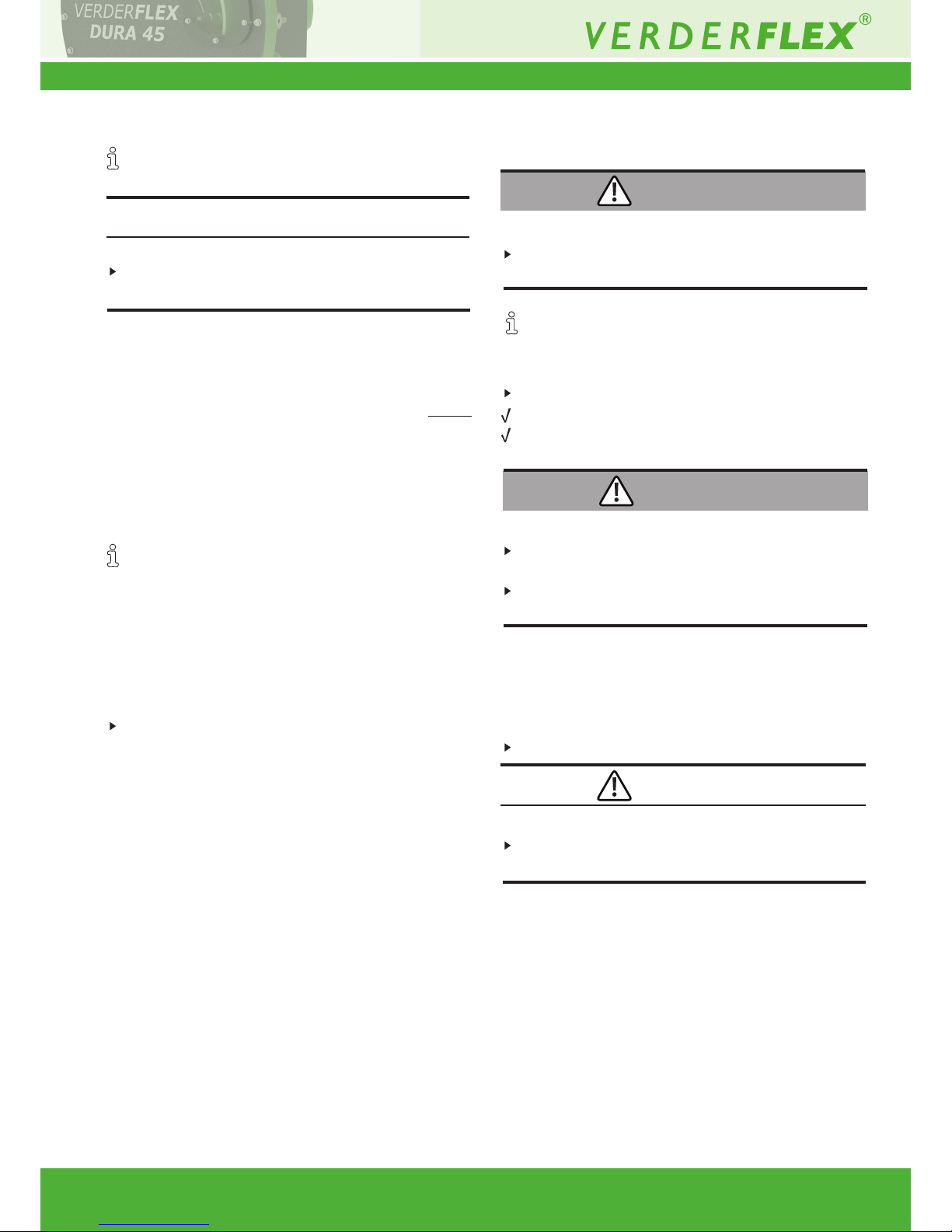
Repairs Measure for return
...at the customer’s
premises
...at the manufacturer’s
premises
...at the manufacturer’s
premises for warranty
repairs
– Return the defective
component to the
manufacturer.
– Decontaminate if
necessary.
– Flush the pump and
decontaminate it if it
was used for hazardous
pumped liquids.
– Only in the event of
hazardous pumped liquid,
ush and decontaminate
the pump
Table 8 Measures for return
Page 19
Dura 45 3.1v-07/2016
7.3.3 Rebuild / Repair
Reinstall the components, in accordance with the
marks applied.
Material damage due to unsuitable components!
Always replace lost or damaged bolts with bolts of the
same strength and material.
1. Observe the following during the installation:
– Replace worn parts with genuine spare parts.
– Maintain the prescribed tightening torques
(g 10.1.3 Tightening torques)
2. Clean all parts (g 10.1.5 Cleaning agents). Do not
remove any markings which have been applied.
3. Reassemble the pump (g refer sectional drawing).
4. Install the pump in the system (g 5 Installation and
connection)
7.3.4 Re-alignment of Rotor after a stall
The rotor is attached to the drive shaft with a friction
coupling, the intent of which is to permit the rotor to
slip in the event of the pump sucking a large solid
object through the inlet. The general effect of such
an event is that the friction coupling absorbs the
initial inertia permitting the motor to overrun
before stalling. This protects the motor, drive shaft
and rotor from failure.
In the event of a rotor stall, induced by external forces;
such as large solids in the hose, the taper joint xing
the rotor to the shaft may need re-setting. To do this:
1. Drain the pump of lubricant, remove the front
cover
2. Slacken each of the clamp bolts
3. Re-torque. The torquing should be done in stages
checking each bolt in turn until no further
movement occurs.
19 | Page
7.4 Hose change
Risk of injury!
Always isolate the power supply before working on
the pump.
The hose change involves removal and re-installing
the port anges.
7.4.1 Dismounting the hose
Draining lubricant
Motor isolated.
System secured against being switched back on
again.
Slip hazard due to spilt lubricant!
Care must be taken when lubricant is drained into
a container.
Dispose of used lubricant in accordance with local
laws and good environmental practices.
1. Remove the drain plug at the rear of the pump.
2. Drain the lubricant into a suitable container.
3. Remove the lower ange and allow any excess
lubricant to drain out.
Removing the hose
Risk of injury if the hose is expelled too quickly
Slowly remove the hose by running the motor at
a reduced speed
1. Remove both the anges.
2. Use the motor to drive out the old hose. If no power
is available, remove the fan cover and turn the fan
shaft by hand or using suitable leverage.
3. Clean the pump housing.
4. Inspect the anges for damage and signs of wear.
7.4.2 Re-installing the hose, port anges, lubricant
rell and tting the inspection window
- Follow step by step, the instructions listed in
section g5.6 (Installing the hose)
WARNING
WARNING
CAUTION
NOTE
Page 20

Dura 45 3.1v-07/2016
7.5 Ordering spare parts
For trouble-free replacement in the event of faults,
we recommend keeping spare parts available
on site.
The following information is mandatory when ordering
spare parts (g Name plate):
– Pump model
– Year of manufacture
– Part number / Description of part required
– Serial number
– Quantity
8. Storing pumps and hoses
Verderex pumps are designed for continuous use,
however, there may be instances when pumps are
withdrawn from use and stored for extended periods.
We recommend certain pre-storage actions and
precautions be taken whilst pumps and their
components are not in use.
Similarly, hoses and lubricants may be held in stock
to service working pumps and their recommended
storage conditions are advised.
8.1.1 Pre-Storage Actions
– The hose should be removed from the pump and
lubricant drained out from the pump casing.
– The pump casing should be washed out allowed to
dry and any external build up of product removed.
8.1.2 Cleaning Protocol for hoses
VERDERFLEX hoses should be cleaned with the following
protocol –
NBRF Hoses:
VERDERFLEX NBRF food grade hoses should
be cleaned with the following protocol:
1 First ush 0.5% Nitric Acid (HNO3) solution at
up to 60°C
2 Second ush 4% Caustic soda (NaOH) solution
and eventually steamed open ends for 15 minutes
at up to 110°C
3. Final ush: ush with clean water to remove
all traces of cleaning solutions
20 | Page
Under no circumstances should VERDERFLEX NBRF
food grade hoses be cleaned with Sodium hypochlorite
(NaOCl) based cleaning solutions, neither should the above
concentrations, exposure, durations or temperatures be
exceeded.
EHEDG Approval
VERDERFLEX NBRF food grade hoses can be used with suitably
specied VERDERFLEX pumps to form an EHEDG accredited
hygienic pumping system. To comply with this certication both
the approved particle velocity must be maintained during the
cleaning cycle and the appropriate hygienic port anges tted.
Should a pump to this specication be required, it should be agreed
with your local VERDERFLEX distributor before the pump is
supplied.
Food Grade Approval
All VERDERFLEX NBRF food grade hoses’ inner liners are
certied as compliant to FDA – CFR 21 Parts 170 to 189 – Item
177.2600
Hose Description
All VERDERFLEX NBRF food Grade hoses consist
of a smooth black inner food grade liner bonded to a
non-food grade outer. The inner liner is a taste-free and odourless.
Hose Installation
All VERDERFLEX NBRF food Grade hoses must
be installed in accordance with the procedures dened
in the VERDERFLEX Operating and Maintenance manual.
Identication
VERDERFLEX NBRF food Grade hoses can be identied by:
a) Both an external Yellow Coding / Identication tape
and an additional white longitudinal stripe
Page 21

Dura 45 3.1v-07/2016
Pump Installation
VERDERFLEX pumps using VERDERFLEX NBRF Food Grade
hoses must be installed in accordance with recommendations
made by the pump’s supplier. In particular, special care must
be given to the suction and discharge line conditions and that
the hose is shimmed in accordance with VERDERFLEX’s
recommendations. Should there be any doubt about any
installation details, these must be discussed with the pumps’
supplier.
Particle Release
All hoses will release small quantities of rubber into the product
stream, especially immediately after the hose installation and
just prior to hose failure. Whilst the rubber released will be food
grade particles, these may cause end-user concerns about
contamination and so we recommend suitable particle capturing
devices such as lters are tted into the pump’s discharge line.
8.1.3 Storage Conditions
– Pumps should be stored in a dry environment, out
of direct sunlight. Depending on these conditions,
it may be advisable to place a moisture-absorbing
product, such as Silica gel, inside the pump’s casing
or to coat the pump’s inner surfaces with moisture-
repelling oil, such as WD40, whilst the pump is stored.
– Gearboxes may require intermittent attention
as indicated by the gearbox manufacturer’s
recommendations.
– Hoses should be stored as supplied in their wrapper
and should be stored away from direct sunlight and
at room temperature with end caps tted.
– Lubricants should be stored under normal warehouse
conditions with their caps securely fastened.
21 | Page
9. Troubleshooting
9.1 Pump malfunctions
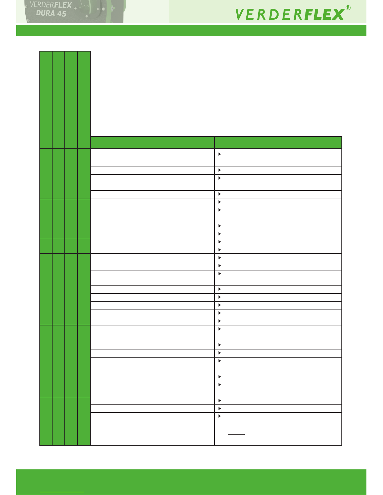
If malfunctions occur which are not specied in the following
table or cannot be traced back to the specied causes, please
consult the manufacturer.
Possible malfunctions are identied and respective cause and
remedy are listed in the table.
Page 22
Dura 45 3.1v-07/2016
22 | Page
Possible Cause Remedy
Incorrect lubricant
Low lubricant level
Product ambient temperature too high
Over shimming of the pump
Blocked suction / bad suction characteristics /
no product
High pump speed
Suction/discharge valve closed
Hose failure
Poor pump selection, incorrect shoe shimming
Suction line too long
Pump speed too high
Suction line bore too small
High product viscosity
Suction/discharge lines not secured properly
Long suction/discharge lines / Damper
malfunction
High product specic gravity / viscosity
Under-sized suction/discharge diameter
Insufcient lubricant in the casing
Inlet pressure too high
Blocked hose / incorrectly tted
Large particles in the product
Abnormally high pump temperature
Low ow/pressure
Pump and pipe-work vibrating
Hose pulled in to pump housing
X - - -
X X - -
X - X -
- X - -
- - X -
- - - X
Consult the manufacturer to obtain correct
lubricant.
Add required amount.
Consult the manufacturer regarding maximum
temperature.
Check for and remove excess shims.
Check pipe-work and valves for blockages.
Check that the suction pipe-work is as short
and as large in diameter as feasible.
Correct the piping layout.
Consult the manufacturer.
Reduce speed to a minimum.
Consult the manufacturer.
Open suction/discharge valve.
Replace hose(g 7.4 Hose change)
Consult the manufacturer to check pump
selection.
Consult the manufacturer.
Consult the manufacturer.
Consult the manufacturer.
Consult the manufacturer.
Check and secure suction/discharge lines.
Shorten long suction/discharge lines
wherever possible.
Consult the manufacturer.
Consult the manufacturer.
Increase suction/discharge pipe-work
diameter.
Fit damper.
Check lubrication chart and add the required
amount of lubrication.
Reduce the inlet pressure.
Check the hose and remove any blockages.
Mount sieve or lter in suction line to avoid
very large particles from entering the hose.
Do not allow lters to limit suction below
accepted levels.
Table 9 Pump troubleshooting list
Page 23
Dura 45 3.1v-07/2016
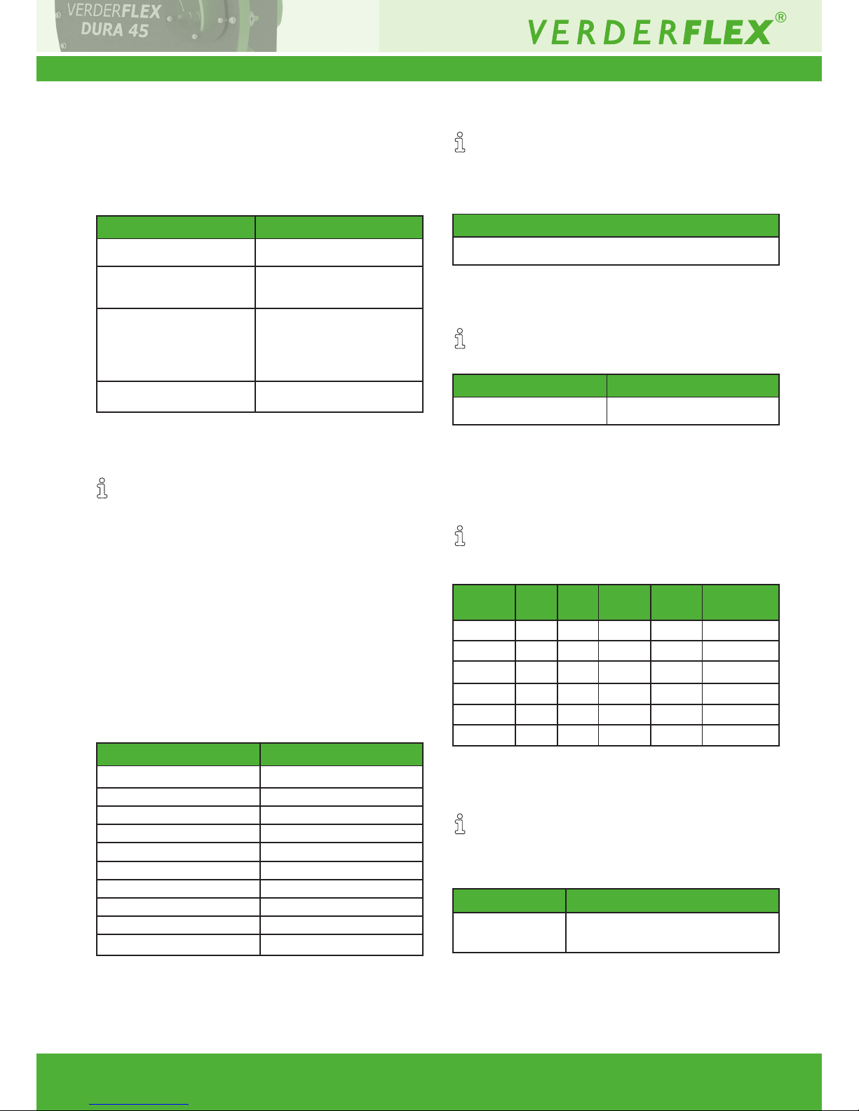
10.1.4 Preservatives
Use e.g. RUST-BAN 335 or similar preservatives on
bare metal.
10.1.5 Cleaning agents (After hose is removed)
Table 12 Cleaning agents
10.1.6 Lubricants
Recommended lubricants for longer hose life
are VERDERLUBE or VERDERSIL.
Table 13 Amount of Lubricant
*The pump is lled to the lowest screw hole on the window.
10.1.7 Shimming
Number of shims required remains unaffected
by change in rpm of the pump. Each shim is 0.5 mm
thick.
Table 14 Number of shims required
10.1.8 Rotor setting distance
The rotor is factory aligned, but for maintenance or
assembly from bareshaft kit, the rotor should be
aligned at the following distance.
Table 15 Rotor setting distance
10. Appendix
10.1 Technical Specications
10.1.1 Pump Specications
Table 10 Pump Specications
10.1.2 Ambient conditions
Operation under any other ambient condition would
require approval from the manufacturer
Operating conditions
• Ambient temperature –5 °C to +45 °C
• Relative humidity – long—term ≤ 85 %
• Setup height above sea level ≤ 1000
Storage conditions
• Ambient temperature +10 °C to +50 °C
• Relative humidity – long—term ≤ 85 %
10.1.3 Tightening torques
Tightening torques should be applied at the below
mentioned torque values:
Table 11 Pump fastener tightening torques
23 | Page
Size
Position
Value
Torque values
Max. delivery pressure
Temperature of pumped
liquid
Max. continuous
operation pump
speeds
Dimensions
Cleaning agents
Wax solvents, diesel parafn, alkaline cleaners, warm water
Inspection Window
Port ange
Rotor shoe
Bearing housing to casing
Gearbox to bearing housing
Motor to gearbox
Frames to casing
Front cover
Rotor mounting bush
Seal Plate
16 bar
< 100 °C
90 rpm at 0 bar
80 rpm at 5 bar
70 rpm at 10 bar
40 rpm at 16 bar
g Setup drawing
3.4 Nm
27 Nm
50 Nm
90 Nm
65 Nm
90 Nm
35 Nm
27 Nm
35 Nm
3.4 Nm
Pump type Amount of Lubricant
Dura 45 7.5*Litres (2.2 US Gallons)
Pump type Rotor setting distance (mm)
Dura 45 3mm from the front of casing
to the front of rotor shoe
Hose
material 0 bar 6 bar 7.5 bar 10 bar 16 bar
EPDM 3 5 – 6 8
NR 3 4 – 7 9
NBR 3 4 – 8 N/A
CSM 4 5 – 8 10
FKM 5 6 6 N/A N/A
NBRF 8 8 N/A N/A N/A
Page 24

Dura 45 3.1v-07/2016
24 | Page
11 List of Figures and Tables
11.1 List of gures
Figure 1 Name plate 3.2.1
Figure 2 Layout 3.3
Figure 3 Fastening lifting gear to pump unit 4.1.2
Figure 4 Shimming 5.4
Figure 5 Installing motor gearbox 5.5.1
Figure 6 Inserting Hose 5.6.1
Figure 7 Fitting the port ange-insert 5.6.2
Figure 8 Fitting the port ange 5.6.2
Figure 9 Bolting down the ange 5.6.2
Figure 10 Filling pump with lubricant 5.6.3
Figure 11 Mounting the inspection window 5.6.4
11.2 List of tables
Table 1 Target groups and their duties 1.1
Table 2 Warnings and consequences of
disregarding them 1.2
Table 3 Symbols and their meaning 1.2
Table 4 Do’s and Don’ts 5.3
Table 5 Measures to be taken if the pump is shut down 6.3
Table 6 Measures depending on behaviour of
the pumped liquid 6.3
Table 7 Maintenance schedule 7.2.2
Table 8 Measures for return 7.3.2
Table 9 Pump troubleshooting list 9.1
Table 10 Pumps specications 10.1.1
Table 11 Pump fastener tightening torques 10.1.3
Table 12 Cleaning agents 10.1.5
Table 13 Amount of Lubricant cover 10.1.6
Table 14 Number of shims required 10.1.7
Table 15 Rotor settings distance 10.1.8
Table 16 Declaration of conformity according
to EC Machine Directive 12
Page 25
Dura 45 3.1v-07/2016
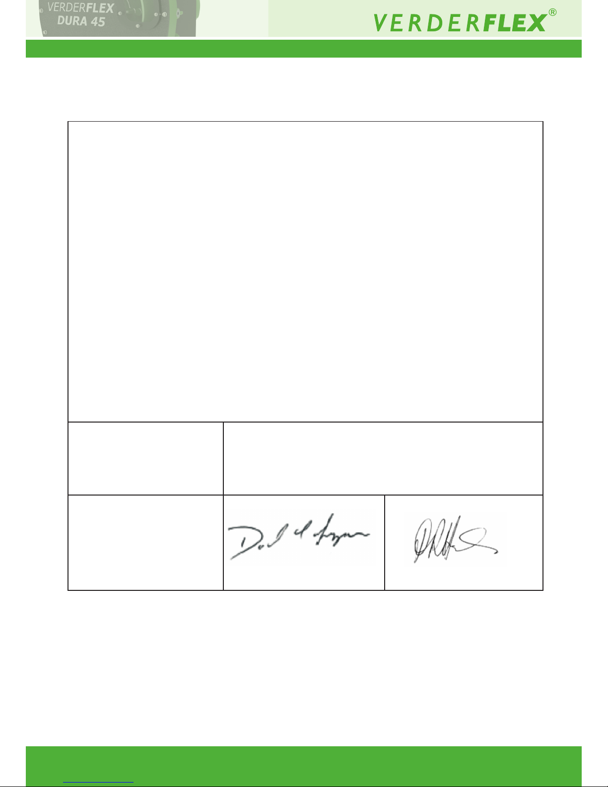
12 Declaration of conformity according to EC Machine Directive
25 | Page
EC declaration of conformity according to machine directive, appendix II A
We,
VERDER Ltd., Unit 3 California Drive, Castleford
hereby declare that the following machine adheres to the relevant EC directives
detailed below
Designation Dura 45
EC directives:
• Machine Directive (2006/42/EC)
• Low-voltage directive (2014/35/EU)
• EMC directive (2014/30/EU)
Applicable harmonized norms:
• EN ISO 12100: 2010
Responsible for the documentation
Date: 01/07/2016
VERDER Ltd.
Unit 3 California Drive
Castleford
WF10 5QH
UK
Company stamp / signature:
David Sampson
Head of Development/Construction
Company stamp / signature:
David Hoyland
Head of Quality
Table 16 Declaration of conformity according to EC Machine Directive
 Loading...