

Verderflex Dura 7, Dura 5, Dura 10, Dura 25, Dura 35 Operating Manual
...
Version 4.0v-06/2013
Print No. 01
Peristaltic Industrial Hose Pump
Operating Manual Dura 5, 7, 10, 15, 25, 35

Version 4.0v-06/2013
Dura 5, 7, 10 , 15, 25, 35
pumps. This document must be read and understood thoroughly prior to installation of unit,
Print-No. 01
The information in this document is essential for the safe operation and servicing of Verderflex®
Dura
electrical connection and commissioning.
Dura 5 - 35 4.0v-06.2013 2 | Page

Table of contents
Table of contents
1. About this document
1.1 Target groups
1.2 Warnings and symbols
2. Safety
2.1 Intended use
2.2 General safety instructions
2.2.1 Product safety
2.2.2 Obligation of the operating company
2.2.3 Obligation of personnel
2.3 Specific hazards
2.3.1 Hazardous pumped liquids
2.3.2 Lubricants
2.3.3 Sharp edges
3. Layout and function
3.1 Design details
3.2 Labelling
3.2.1 Name Plate
3.3 Layout
3.4 Bearings and Lubrication
4. Transport, stor age and disposal
4.1 Transport
4.1.1 Unpacking and inspection on delivery
4.1.2 Lifting
4.2 Treatment for storage
4.3 Interim storage before installation
4.4 Disposal
5. Installation and connection
5.1 Preparing for installation
5.1.1 Checking the ambient conditions
5.1.2 Preparing the installation site
5.1.3 Preparing the foundation and surface
5.2 Installation at site
5.3 Planning the pipes
5.3.1 Specifying supports and flange connections
5.3.2 Specifying nominal diameters
5.3.3 Specifying pipe lengths
5.3.4 Optimizing cross-section of pipe work
5.3.5 Providing safety and control devices
(recommended)
5.4 Assembling the pump
5.4.1 Assembling pump case
5.4.2 Installing the drive shaft
5.4.3 Installing the rotor
5.4.4 Assembling the front cover
5.4.5 Assembling Gear motor unit
5.5 Electrical connection
5.5.1 Connecting to power supply
5.6 Installing the Hose
5.6.1 Inserting the hose
5.6.2 Fitting the port flange (Standard assembly)
5.6.3 Fitting the port flange (Split flange assembly)
5.6.4 Filling the pump with lubricant
5.7 Connecting the pipes
5.7.1 Installing the piping
Operation
6.
6.1 Pre-commissioning the pump
6.1.1 Checking the direction of rotation with dry
pump
6.1.2 Starting the pump
6.1.3 Switching off
6.2 Operation
6.2.1 Switching on
6.2.2 Switching off (Refer to → 6.1.3)
6.3 Shutting down the pump
6.4 Start-up following a shutdown
period
6.5 Operating the stand-by pump
7. Maintenance
7.1 Inspections
7.2 Maintenance
7.2.1 Cleaning the pump
7.2.2 Maintenance schedule
7.3 Repairs
7.3.1 Preparations for dismounting
7.3.2 Returning the pump to the manufacturer
7.3.3 Rebuild / Repair
7.4 Hose change
7.4.1 Dismounting the hose
7.4.2 Re-installing the hose, port flanges, lubricant
refill and fitting the inspection window
7.5 Ordering spare parts
8. Storing pumps and hoses
8.1.1 Pre-Storage Actions
8.1.2 Cleaning Protocol for hoses
8.1.3 Storage Conditions
9. Troubleshooting
9.1 Pump malfunctions
10. Appendix
10.1 Technical Specifications
10.1.1 Pump Specifications
10.1.2 Ambient conditions
10.1.3 Tightening torques
10.1.4 Preservatives
10.1.5 Cleaning agents (After hose is removed)
10.1.6 Lubricants
10.1.7 Rotor options
10.2 List of Figures and Ta ble s
10.2.1 List of figures
10.2.2 List of tables
10.3 Declaration of conformity according to EC
Machine Directive
Dura 5 - 35 4.0v-06.2013 3 | Page
About this document
Target group
Duty
Operating company
Keep this manual available at the operation site of the equipment,
Ensure that personnel read and follow the instructions in this
manual and the other applicable documents, especially all safety
itional rules and regulations referring to the
Qualified personnel, fitter
Read, observe and follow this manual and the other applicable
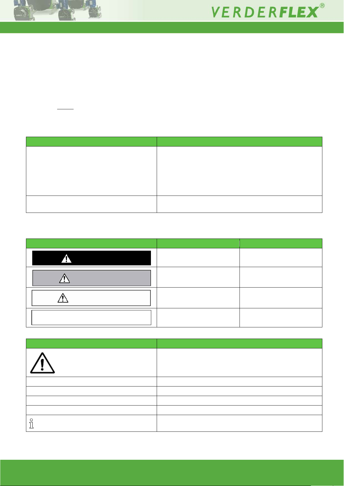
Warning
Risk level
Consequences of disregard
Immediate acute risk
Death, serious bodily harm
Potential acute risk
Death, serious bodily harm
Potential hazardous situation
Minor bodily harm
Potential hazardous situation
Material damage
Symbol
Meaning
Safety warning sign in accordance with DIN 4844 - W9
safety warning sign
Instruction
1. , 2. , ...
Multiple-step instructions
Precondition
→
Cross-reference
Information, recommendation
NOTE
CAUTION
WARNING
DANGER
1. About this document
Verderflex range of P eristaltic pumps, Dura 5 - 35, has be en developed according to the latest technology a nd
subject to continuo us qualit y control. These op erating i nstructions are int ended to facilitat e fam iliarization with the
pump and its designated use. The relevant information will act as a guideline for you in operating the pump;
alternative courses of actio n are also describ ed shoul d you be unable, f or any r eason, t o follow t hose proce dures
initially given. You are advised to follow these guidelines to achieve maximum efficiency. These operating
instructions do not
observed by all, including the personnel called in for installation.
1.1 Target groups
tak e into accoun t local regulatio ns; the operator m ust ensure that s uch regulations ar e strictly
also available for later reference.
instructions and warnings.
Observe any add
system.
Tab. 1 Target groups and their duties
1.2 Warnings and symbols
Tab. 2 Warnings and consequences of disregarding them
Take note of all information highlighted by the
documents, especially all safet y instructi ons and war ni ngs.
and follow the instructions to avoid injury or death.
Tab. 3 Symbols and their meaning
Dura 5 - 35 4.0v-06.2013 4 | Page

2. Safety
The manufacturer does not accept any liability for
damage resulting from disregard of this
documentation.
Observe the following regulations before carrying out
any work.
2.1 Intended use
Only use the pump to handle compatible fluids as
recommended by the manufacturer (→ 10.1 Technical
specifications).
Adhere to the operating limits.
Safety
Keep this manual and all other applicable documents
complete, legible and accessible to personnel at all times.
Refrain from any pro ced ure or action that would pose a risk
to personnel or third parties.
In the event of any safety-relevant faults, shut down the
pump immediately and have the malfunction corrected by
qualified personnel.
The installation of the pump, associated pipe work and
electrical fittings must comply with the requirements of
installation given in this manual and any local national or
regional health and safety regulations
Consult the manufacturer regarding any other use of the
pump.
Pumps delivered without a mo tor must be f itted with a motor
in accordance with the provisions of EC Machine Directive
2006/42/EC or local regulations when outside EC.
Prevention of obvious misuse (examples)
Note the operating limits of the pump with regard to
temperature, pressure, flow rate and motor speed (→ 10.1
Technical specif ic atio ns).
Do not operate the pump while the inlet/outlet valve is
closed.
Only install the pump as recommended in this manual. For
example, the following are not allowed:
–
Installing the pump without proper support.
–
Installation in the immediate vicinity of extreme hot or
cold sources.
2.2 General safety instructions
2.2.1 Product safety
These operating instructions contain fundamental
information which must be complied with during
installation, operation and maintenance. Therefore this
operating manual mu st be r ead and understood both by
the installing personnel and the responsible trained
personnel / operators prior to installation and
commissioning, and it must always be kept easily
accessible within the operating premises of the
machine.
Not only must the general safety instructions laid down
in this chapter on “Safety ” be complied w ith, but also th e
safety instructions outlined under specific headings.
2.2.2 Obligation of the operating company
Safety-conscious operation
Ensure that the following safety aspects are observed and
monitored:
–
Adherence to intended use
–
Statutory or other safety and accident-prevention
regulations
–
Safety regulations governing t he ha ndl ing of
hazardous substances if appl icable
–
Applicable standards and guidelines in the country
where the pump is operated
Make personal protective equipment available pertinent to
operation of the pump; as required.
Qualified personnel
Ensure that all personnel tasked with work on the pump
have read and understood this manual and all other
applicable documents, including the safety, maintenance
and repair information, prior to use or installation of the
pump.
Organize responsibilities, areas of competence and the
supervision of personnel.
Have all work carried out by specialist technicians only.
Ensure that trainee personnel are under the supervision of
specialist technicians, at all times, when working on the
pumping system.
Safety equipment
Provide the following safety equipment and verify its
functionality:
–
For hot, cold and moving part s: safety guar ding should
be provided by the operating company.
–
For potential build up of electrostatic char ge: ens ure
appropriate grounding if and when required.
Operate the pump only if the pumping unit and all
associated systems are in good functional condition.
Only use the pumping system as intended, fully aware of
safety and risk factors involved, and in adherence to the
instructions in this manual.
Dura 5 - 35 4.0v-06.2013 5 | Page
Layout and function
The warranty is voided if the customer fails to follow
any and all instructions, warnings and cautions in this
document. Verder has made every effort to illustrate
and describe the product(s) in this document. Such
illustrations and descr iptions are, how ever , for t he sole
purpose of identificat ion and
express or imply a
warranty that the product s are merchantabl e or fit for a
particular purpose, or that the products will
necessarily conform to the illustration or descriptions.
Obtain the manufacturer's approval prior to carrying
out any modifications, rep airs or alterations during the
warranty period. Only use genuine parts or parts that
have been approved by the manufacturer.
For further details regarding warranty, please refer
terms and conditions.
It is imperative that the instructions contained in
this manual are complied with by the operating
personnel at all times.
Peristaltic hose pump, Verderflex Dura, is simple by
design in its construction and operation. The medium
to be pumped does not come into contact with any
moving parts and is totally contained within a robust,
heavy
consists of an inner
layer, two – six reinforcement layers and an outer
layer. A rotor passes along the length of the hose,
compressing it. This motion forces the contents of the
hose directly in front o f the roto r to move forw ard along
the length of the hose in a ‘positive displacement’,
peristaltic movement. In the wake of the rotor’s
compressing action, the natural elasticity of the
polymer reinforced rubber forces the ho se to open an d
regain its round profile, creating suction pressure,
which recharges the pump.
Verderflex Dura is a twin lobe, single rotor, peristaltic
pump with quick-fit tapered port flange design which
clamps and seals in one easy movement to speed
hose replacement.
Warranty
do not
2.2.3 Obligation of personnel
Pump and associated components:
–
Do not lean or step on them or use as climbing aid
–
Do not use them to support boards, ramps or beams
–
Do not use them as a fixing point for winches or
supports
–
Do not de-ice using gas burners or similar tools
–
Do not remove the safety guarding for hot, cold or
moving parts during operation.
Reinstall the safety equipment on the pump as required by
regulations after any repair / maintenance work on the
pump.
3. Layout and function
-duty hose, which usually
3.1 Design details
3.2 Labelling
3.2.1 Name Plate
2.3 Specific hazards
2.3.1 Hazardous pumped liquids
Follow the statutory safety regulations when handling
hazardous pumped liquids (e.g. hot, flammable, poisonous
or potentially harmful). Use appropriate personal protective
equipment when carrying out any work on the pump.
2.3.2 Lubricants
Ensure that the lubricant and p umpe d liq uid ar e co mpat ibl e
with each other. This is a precautionary measure in case of
accidental hose burst whereby the pumped liquid comes in
contact with the lubricant (Refer datasheet for lubricant to
ensure compatibility)
2.3.3 Sharp edges
Pump parts, such as the shims, can be sharp
–
Use protective gloves when carrying out any work on
the pump
Dura 5 - 35 4.0v-06.2013 6 | Page
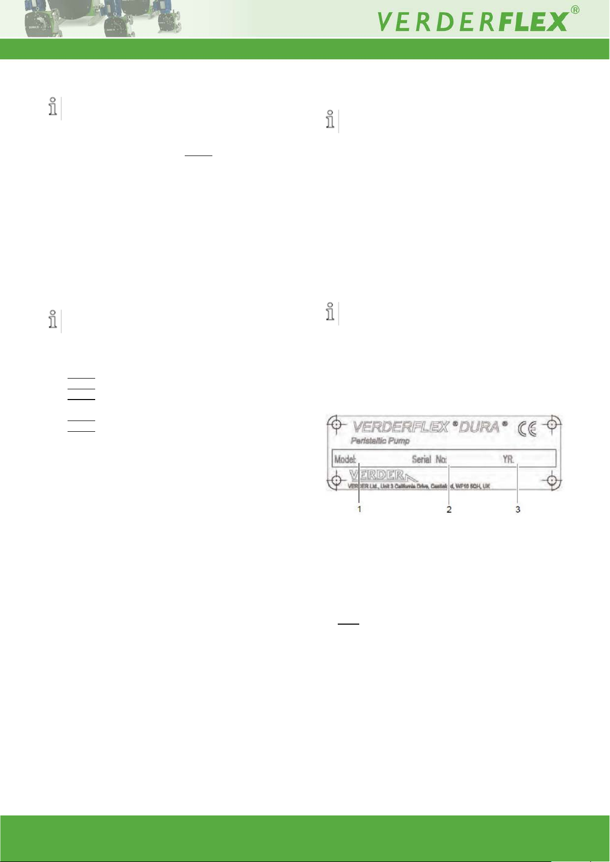
Figure 1 Name plate
1 Pump type
2 Serial number
3 Year of manufacture
Note: When requesting spares, the model and serial
number should always be quoted.
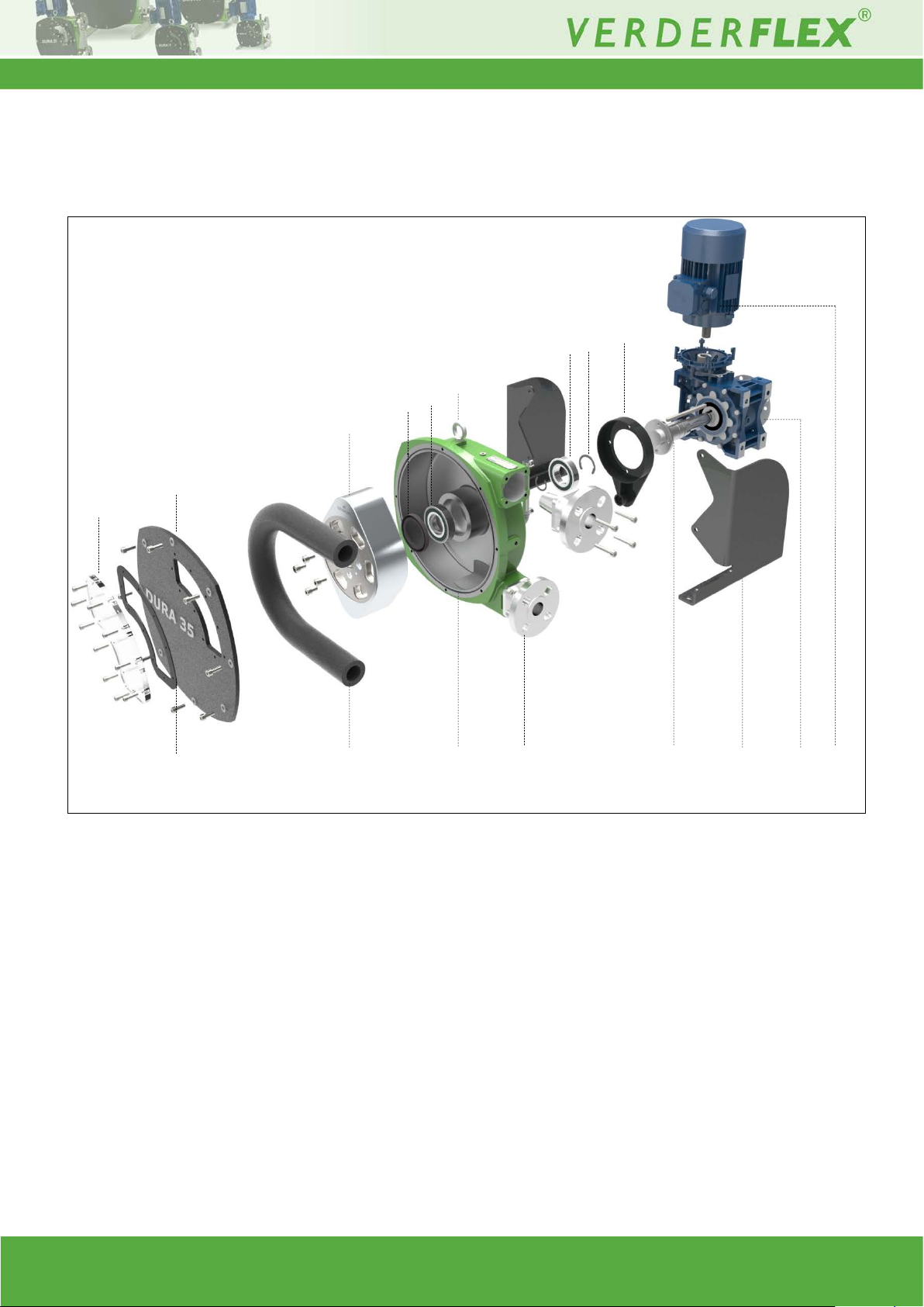
3.3 Layout
1 Inspection window
7 Front Bearing
13 Torque arm
2 Inspection window gasket
8 Pump casing
14 Drive shaft
3 Front cover
9 Lifting eye
15 Frames
4 Hose
10 Port flange
16 Gearbox
5 Rotor
6 Lip seal
11 Bearings
12 Crescent clip
17 Motor
1 2 4
10 9 11
14
16 3 5
17
13 8 15 6 7
12
Layout and function
Figure 2 Layout (generic view)
3.4 Bearing s an d Lubrication
Pump: To be filled at installation with appropriate
lubricant if not supplied pre filled. (→10.1.6
Lubricants)
Bearings are sealed units and need no additional
lubricant
Dura 5 - 35 4.0v-06.2013 7 | Page
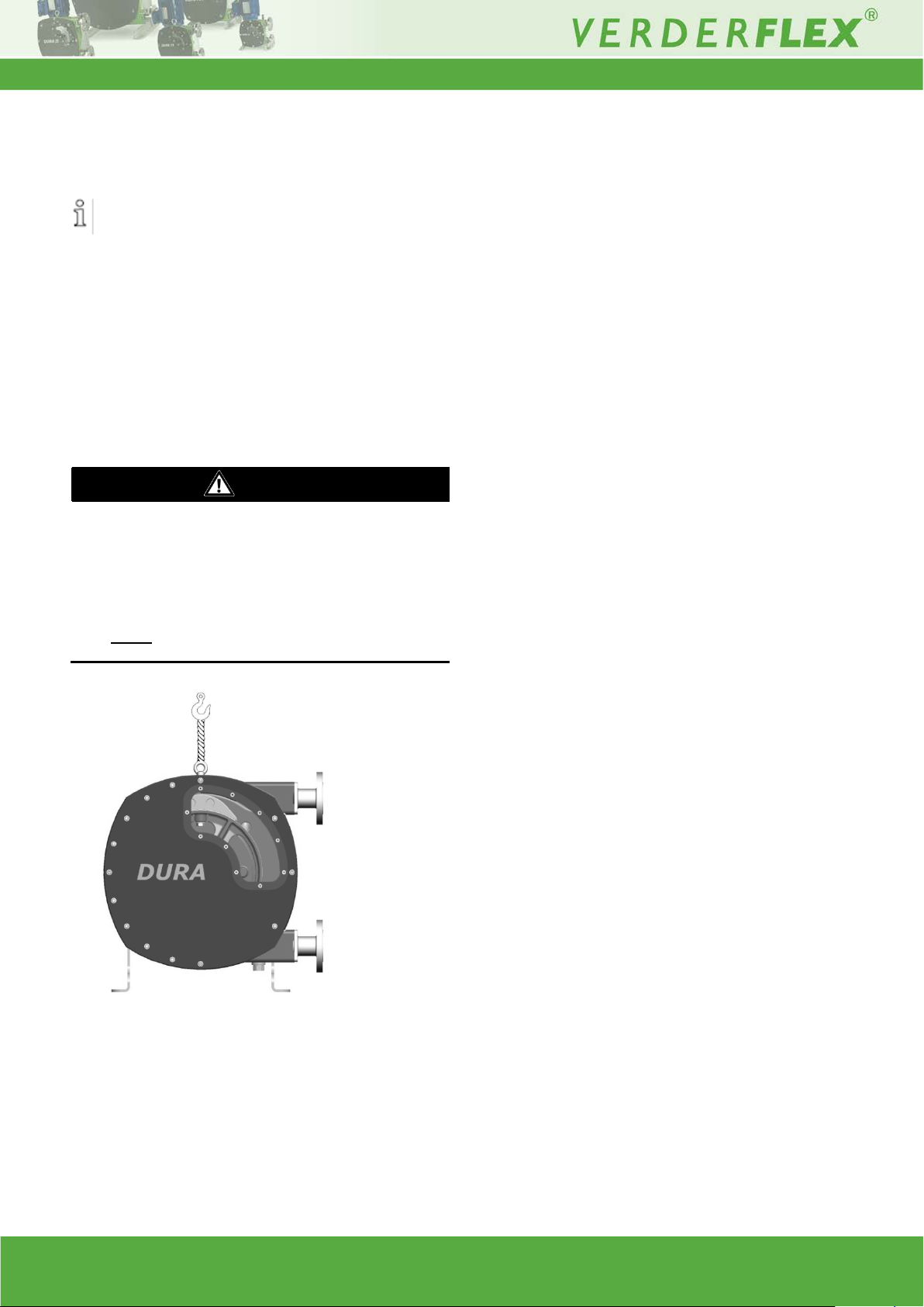
Always transport the unit in an upright position and
ensure that the unit is securely attached to the pallet.
DANGER
can be caused by falling
Fasten the lifting ge ar t o the lift ing ey e as shown i n th e
4. Transport, storage and disposal
4.1 Transport
4.1.1 Unpacking and inspection on delivery
1. Unpack the pump/pump unit upon delivery and
inspect it for transport damage.
2. Report any transport damage to the
manufacturer/distributor immediately.
3. Retain the pallet if any further transport is required.
4. Dispose all packaging material according to local
regulations.
4.1.2 Lifting
Death or crushing of limbs
loads!
1. Use lifting gear appropriate for the total weight to be
transported.
2.
following illustration.
3. Do not stand under suspended loads.
Figure 3 Fastening lifting gear to pump unit
Dura 5 - 35 4.0v-06.2013 8 | Page
4.2 Treatment for storage
Unpainted steel surfaces should be coated with rust
inhibitor and the unit should be stored in a dry, dust
free environment not exceeding 60°C
NOTE
–
Renew treatment if necessary.
NOTE
With prolonged use, pump parts can get contaminated
by poisonous or radioactive pu mped liquids to su ch an
extent that cleaning may be insufficient.
WARNING
Dispose of the pump unit and associated parts in
NOTE
NOTE
immediately before connecting the pipes to the pump
Material damage due to inappropriate treatment for
storage!
Treat all internal and external bare metal pump parts for
storage.
5. Installation and connection
Material damage due to unauthorized modification on
pump unit!
Do not make any structural modifications to the pump
unit or pump casing
Do not carry out any welding work on the pump unit or
pump casing
4.3 Interim storage before installation
Material damage due to inappropriate storage!
Treat the pump with preservatives compatible with
pumped media (precaution in case of spillage).
1. Close all opening s with blanks, plugs or plasti c covers.
2. Make sure the storage room meets the following
conditions:
–
Dry, humidity not to exceed 80%
–
Out of direct sunlight
–
Frost-free; temperature range 0 to 40°C
–
Vibration-free; minimize
–
Dust-free; minimize
*Storage information for pump s withdrawn from use is listed
in section 8, Storing pumps and hoses.
4.4 Disposal
Risk of poisoning and environmental damage by the
pumped liquid or oil!
Use suitable personal protective equipment when
carrying out any work on the pump.
Prior to disposal of the pump:
–
Drain and dispose the lubr ican t in accor dance w ith
local regulations .
–
Collect and dispose of any leaking pumped liquid
or oil in accordance with local regulations.
–
Neutralize residues of pumped liquid in the pump.
accordance with statutory reg u latio ns.
Material damage caused by ingress!
–
Do not remove any protective flange covers until
5.1 Preparing for installation
5.1.1 Checking the ambient conditions
1. Make sure that the operating conditions are complied
with (→ 10.1.1 Pump specifications)
2. Make sure the r equired ambient c onditions are fulfil led
(→ 10.1.2 Ambient conditions)
5.1.2 Preparing the installation site
Ensure the installation site meets the following
conditions:
–
Pump is freely accessible from all sides
–
Sufficient space is available for the
installation/removal of the pipes and for maintenance
and repair work, especially for the removal and
installation of the hose.
5.1.3 Preparing the foundation and surface
Make sure the foundation and surface meet the
following conditions:
–
Level
–
Clean (no oil, dust or other impurities)
–
Capable of bearing the w eight of the p ump unit and all
operating forces
–
Ensure the pump is stable and cannot tip over
–
Concrete foundation: Standard concrete strong
enough to support the pump unit under load.
5.2 Installation at site
1. Lift the pump unit (→ 4.1.2 Transport)
2. Put the pump unit down at the installation site.
3. Bolt the pump down; use all 4 holes.
Dura 5 - 35 4.0v-06.2013 9 | Page
 Loading...