

Verdant VX Series, VX-TW-KT-W Installation Manuals
VX-TW-KT-W
VX Series Wireless Thermostat
with an Occupancy Sensor
INSTALLATION MANUAL
www.myamtex.com
®
800-650-3360
V.1 JULY 17, 2017

3
Table of Contents
Introduction .................................................................................................5
Thermostat Installation ...............................................................................8
Pairing the Thermostat and the Control Card ............................................. 8
Installing the Wireless Control Card ............................................................ 9
Mounting the thermostat to the wall ........................................................10
Thermostat Configuration .......................................................................... 11
Setting the thermostat clock ...................................................................... 12
Entering the room number ......................................................................... 13
Configuring the Equipment Settings - Compressor Type ........................... 14
Configuring the Equipment Settings - Electric Heat .................................. 15
Configuring the Equipment Settings - Reversing Valve .............................16
Configuring the Energy Saving Settings .................................................... 17
Testing the thermostat ...............................................................................18
Accessing the Thermostat Settings ............................................................19
Custom Energy Savings Settings ................................................................19
Using the Thermostat Settings Screens ....................................................20
01 – FAN CONTROL MODE ..........................................................................21
02 – 1
ST
STAGE DIFFERENTIAL - HEAT ..........................................................22
03 – 2
ND
STAGE DIFFERENTIAL - HEAT .........................................................23
04 – 1ST STAGE DIFFERENTIAL - COOL ....................................................... 24
05 – INCIDENTAL OCCUPANCY THRESHOLD ............................................. 25
06 – NIGHT OCCUPANCY THRESHOLD ...................................................... 26
07 – FORCED 2ND STAGE HEATING .............................................................27
08 – NIGHT OCCUPANCY START ................................................................ 28
09 – NIGHT OCCUPANCY END ................................................................... 29
10 – TEMPERATURE RECOVERY TIME ........................................................30
11 – RECOVERY TEMPERATURE - HEAT ........................................................31
12 – TEMPERATURE SETBACK DELAY - HEAT ...............................................32
13 – MINIMUM SETBACK TEMPERATURE .................................................. 33
14 – TEMPERATURE SETBACK DELAY - COOL ............................................. 34
15 – MAXIMUM SETBACK TEMPERATURE .................................................. 35
16 – RECOVERY TEMPERATURE - COOL ..................................................... 36
17 – MINIMUM SET POINT ...........................................................................37
www.myamtex.com
800-650-3360
•

4 5
Table of Contents
18 – MAXIMUM SET POINT ......................................................................... 38
19 – TEMPERATURE CONTROL MODE ........................................................ 39
20 – AUTO CHANGEOVER SET POINT OFFSET (DEAD BAND) .................... 40
21 – SETBACK SET POINTS / AUTO-RESTORE ..............................................41
22 – AUTOMATIC HUMIDITY CONTROL
†
.................................................... 42
23 – TEMPERATURE CALIBRATION ............................................................. 43
Thermostat Maintenance ...........................................................................44
Replacing Thermostat Batteries ................................................................ 44
Troubleshooting ......................................................................................... 45
Error Codes ................................................................................................. 45
Thermostat is not controlling the HVAC unit. ..........................................46
Initiating a Master Reset............................................................................47
APPENDIX 1 - Energy Saving Presets ..........................................................48
APPENDIX 2 - Glossary ................................................................................49
Warranty Information ................................................................................50
Technical Specifications ............................................................................. 52
Introduction
Verdant VX Series Energy Management Thermostats for the hospitality
industry deliver unprecedented energy savings without compromising
guest comfort.
An Integrated occupancy sensor uses a combination of motion and
thermal sensing technologies for accurate occupancy detection.
Reliable occupancy detection allows for energy savings when rooms are
unoccupied.
Energy saving presets eliminate the guesswork and make it easy to
adjust the energy saving settings.
Fully configurable energy saving settings allow for customization of the
thermostat energy saving settings to fit any situation.
Comprehensive configuration options ensure full compatibility with
virtually any existing or emerging hospitality HVAC system with up to 2
heat and 1 cool stages.
Built-in wireless mesh-networking enables online management.
www.myamtex.com
800-650-3360
•
www.myamtex.com
800-650-3360
•

6 7
Before You Begin
➤ Determine the appropriate installation location for the thermostat.
➤ Set the HVAC unit to “External Thermostat” (Class 2) mode. Consult
the HVAC unit documentation to determine how to set the HVAC
unit to “External Thermostat” mode.
➤ Consult the HVAC manufacturer’s documentation or use a voltmeter
to determine if the HVAC unit outputs AC or DC power (24V).
If the HVAC unit outputs AC power, make sure that the jumper
on the Wireless Control Card is in the AC position - jumper is
connecting “R” and “COM” pins (Default).
If the HVAC unit outputs DC power, make sure that the jumper
on the Wireless Control Card is in the DC position - jumper is
connecting “COM” and “C” pins.
THE THERMOSTAT SHOULD FACE THE BED AREA OF THE ROOM.
THE THERMOSTAT MUST NOT BE INSTALLED NEAR OR ON
METAL STRUCTURES OR SURFACES INCLUDING METAL AIR
DUCTING THAT MAY BE IN THE WALL.
METAL STRUCTURES AND SURFACES SIGNIFICANTLY REDUCE
THE RANGE OF THE WIRELESS SIGNAL.
NOTICE
FOR INSTALLATION OF THERMOSTATS WITH NETWORKING
CAPABILITIES, REFER TO THE “VX-TW NETWORK INSTALLATION”
MANUAL.
BEFORE INSTALLING THERMOSTATS, CONFIRM WITH A VERDANT
TECHNICAL SUPPORT AGENT THAT THE SERVER IS CONNECTED
TO THE INTERNET BY CALLING 1 877 318 1823.
DO NOT INSTALL THERMOSTATS IF THE SERVER IS NOT
CONNECTED TO THE INTERNET. STOP THE INSTALLATION
AND CONTACT VERDANT TECHNICAL SUPPORT FOR FURTHER
DIRECTION.
www.myamtex.com
800-650-3360
•
www.myamtex.com
800-650-3360
•
8 9
Thermostat Installation
Installing the Wireless Control Card
➤ Power Off HVAC unit;
➤ Connect the control card to the thermostat terminals on the HVAC
unit - refer to the Wiring Table to determine proper connections.
➤ Mount the control card inside of the HVAC unit.
THE WIRELESS CONTROL CARD ANTENNA MUST NOT BE TOUCHING
ANY METAL COMPONENTS OF THE HVAC UNIT.
THE WIRELESS CONTROL CARD ANTENNA MUST FACE THE
THERMOSTAT ON THE WALL AND BE ORIENTED SO THAT ANY
METAL PARTS OF THE HVAC UNIT DO NOT OBSTRUCT THE WIRELESS
COMMUNICATION TO THE THERMOSTAT AND, IN CASE OF A
NETWORK INSTALLATION, TO OTHER WIRELESS CONTROL CARDS
AND THE SERVER.
THE WIRELESS CONTROL CARD MUST NOT BE PLACED IN THE HVAC
UNIT CONDENSATION PAN AND MUST BE MOUNTED SO IT CANNOT
FALL INTO THE HVAC UNIT CONDENSATION PAN.
Before You Begin
Pairing the Thermostat and the Control Card
The thermostat and Control Card must be paired in order to operate
together. Once paired, the thermostat cannot be used with another
wireless control card without repeating the pairing procedure.
In case of Network Installation with online management, the
thermostat and the Control Card must be paired with a Network
Programmer specific to the property before the installation.
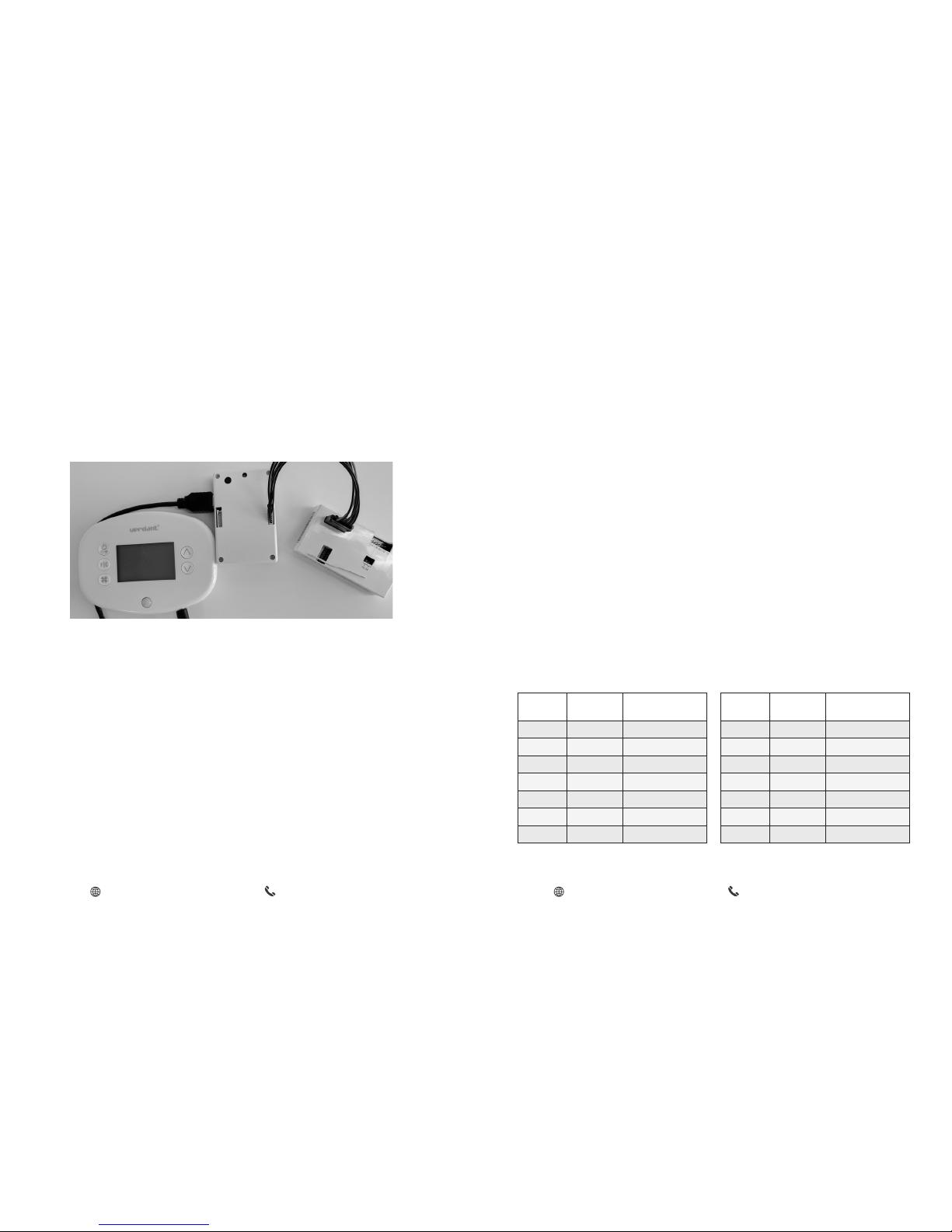
The thermostat and control card must not be powered during the pairing
procedure - remove batteries from the thermostat and unplug the control
card from the HVAC unit during the pairing procedure.
➤ Plug one programmer connector into the thermostat;
➤ Plug the other programmer connector into the control card;
➤ Push the black button on the programmer. The red light on the
programmer should turn on and remain steadily lit;
If the red light on the programmer is blinking or is not steadily lit,
unplug the programmer from the thermostat and the control card
and repeat the steps above.
➤ Unplug the programmer from the thermostat and the control card;
NOTE: If the PTAC unit has only one (1) fan speed, connect both fan
control wires – Green and Purple – to the fan terminal (G).
Wiring Table - 24V AC
Wire
Color
Terminal
Letter
Terminal
Connection
Black C Common
Red R 24V
Yellow Y Compressor
White W Heat
Orange O or B Reverse Valve
Green GH Fan High
Purple GL Fan Low
Wiring Table - 24V DC
Wire
Color
Terminal
Letter
Terminal
Connection
Black R 24V
Red C Common
Yellow Y Compressor
White W Heat
Orange O or B Reverse Valve
Green GH Fan High
Purple GL Fan Low
www.myamtex.com
800-650-3360
•
www.myamtex.com
800-650-3360
•
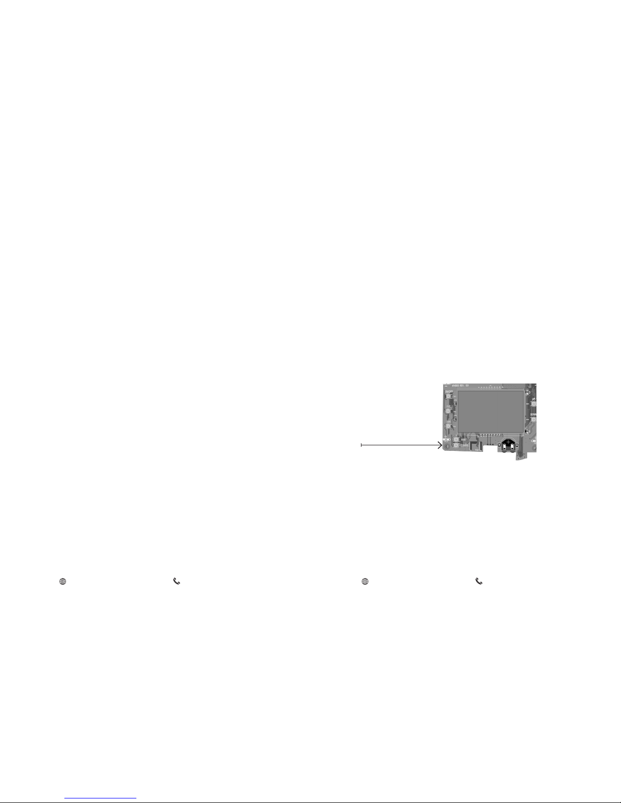
CONFIGURATION BUTTON
NOTE: You can access Thermostat
Configuration settings at any time by
pressing the “Configuration” button.
10 11
➤ Power On the HVAC unit.
Mounting the thermostat to the wall
➤ Remove the thermostat cover;
➤ Use the supplied wall anchors and mounting screws to secure the
thermostat to the wall;
➤ Insert two (2) AA-cell batteries (not supplied) into the thermostat
battery compartment;
➤ Follow the “Thermostat Configuration” instructions;
➤ Replace the thermostat cover and screw in the locking screw;
Thermostat Installation Thermostat Configuration
Once the thermostat is powered, thermostat configuration settings will
appear on the thermostat screen.
In order to properly operate the HVAC unit:
➤ Set the thermostat clock;
➤ Enter the room number;
➤ Configure the equipment settings;
➤ Select Energy Savings Preset;
The thermostat configuration screens have a 30-second time-out. If
no action is taken within three (30) seconds, the thermostat will exit
configuration settings.
NOTE: If the thermostat is connected to a network, the equipment
and the energy saving settings configured on the thermostat will be
ignored and the settings configured online will be applied.
www.myamtex.com
800-650-3360
•
www.myamtex.com
800-650-3360
•
12 13
Thermostat Configuration
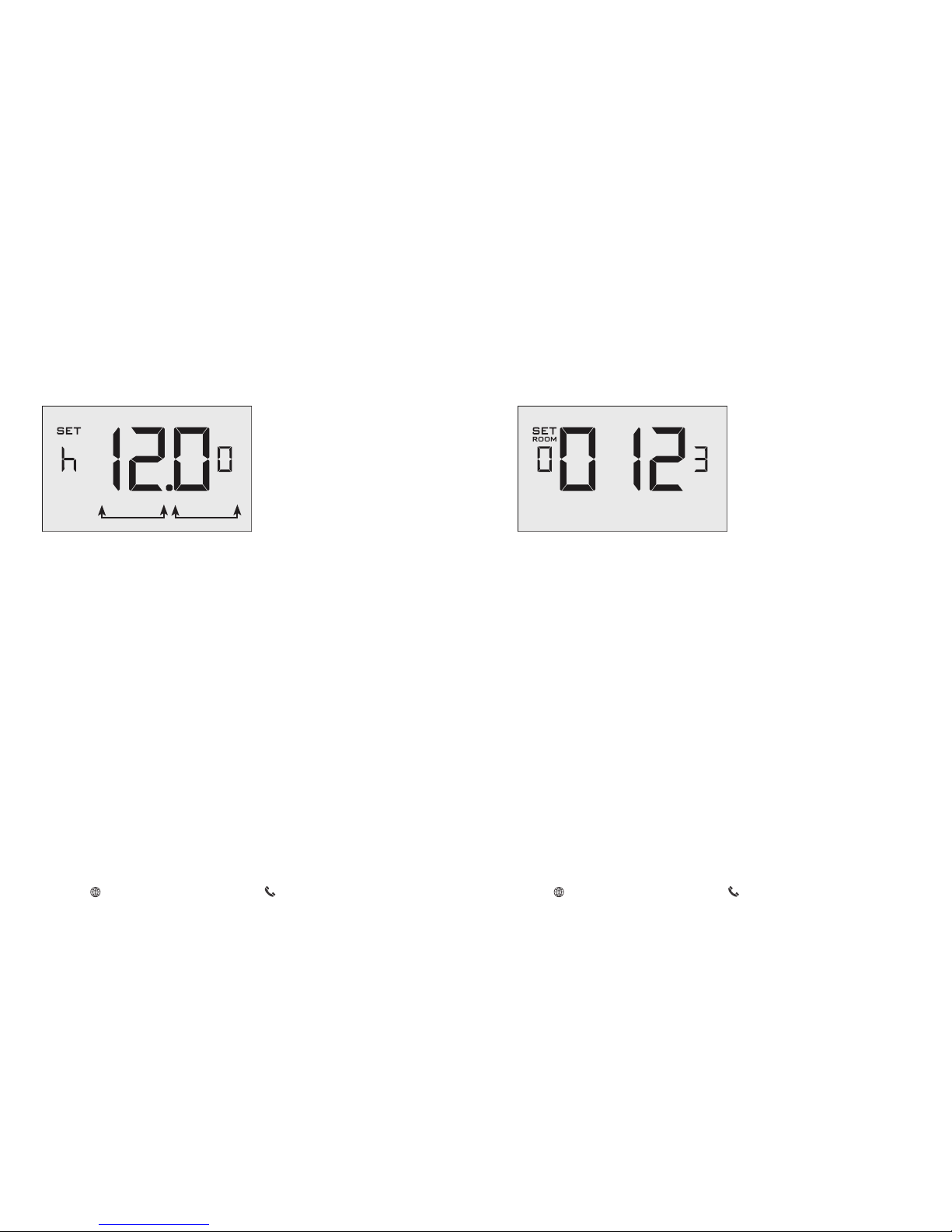
Setting the thermostat clock
Set the thermostat clock to current time in 24h (Military Time) format.
➤ Use the “Up” and “Down” buttons to set the hours;
➤ Press the “Fan” button to advance to the minutes setting;
➤ Use the “Up” an “Down” buttons to set the minutes;
➤ Press the “F/C” button to advance to the next menu;
Setting the clock correctly is crucial for proper operation of the
thermostat.
HOURS MINUTES
Thermostat Configuration
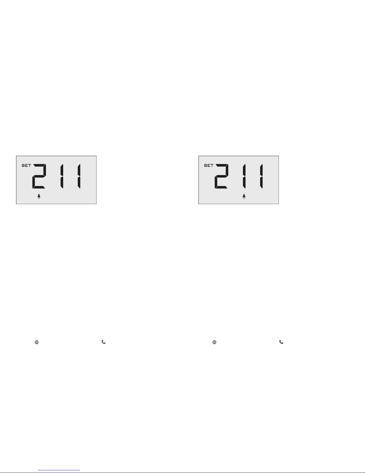
Entering the room number
Enter the room number by changing the digits on the screen. Leading
zeros “0” preceding other digits will be ignored, i.e. Room number “123”
should be entered as “00123”.
➤ Use the “Up” and “Down” buttons to change the digit;
➤ Press the “Fan” button advance to the next digit;
➤ Press the “F/C” button to advance to the next menu;
Entering the room number correctly is crucial for proper operation of
remotely managed thermostats.
www.myamtex.com
800-650-3360
•
www.myamtex.com
800-650-3360
•
14 15
Thermostat Configuration
Configuring the Equipment Settings - Compressor Type
➤ Use the “Up” and “Down” buttons to change the compressor type by
changing the first digit;
0 No Compressor
1 Heat Pump
2* Air Conditioner
➤ Press the “Fan” button to advance to the next setting;
* Indicates default setting;
COMPRESSOR TYPE
Thermostat Configuration
Configuring the Equipment Settings - Electric Heat
➤ Use the “Up” and “Down” buttons to change the Electric Heat setting
by changing the second digit;
0 No Electric Heat
1 * Electric Heat
➤ Press the “Fan” button to advance to the next setting;
* Indicates default setting;
ELECTRIC HEAT
www.myamtex.com
800-650-3360
•
www.myamtex.com
800-650-3360
•
16 17
Thermostat Configuration
Configuring the Equipment Settings - Reversing Valve
➤ Use the “Up” and “Down” buttons to change the Reversing Valve
setting by changing the third digit;
0 OB contact is energized to cool;
1 * OB contact is energized to heat;
Refer to the HVAC unit documentation to determine the
correct OB VALVE setting.
If incorrect OB VALVE Setting is selected, the HVAC unit will
turn on the heating when air conditioning is requested and
turn on the air conditioning when heating is requested;
➤ Press the “Fan” button to advance to the next setting;
➤ Press the “F/C” button to advance to the next menu;
* Indicates default setting;
REVERSING VALVE
Thermostat Configuration
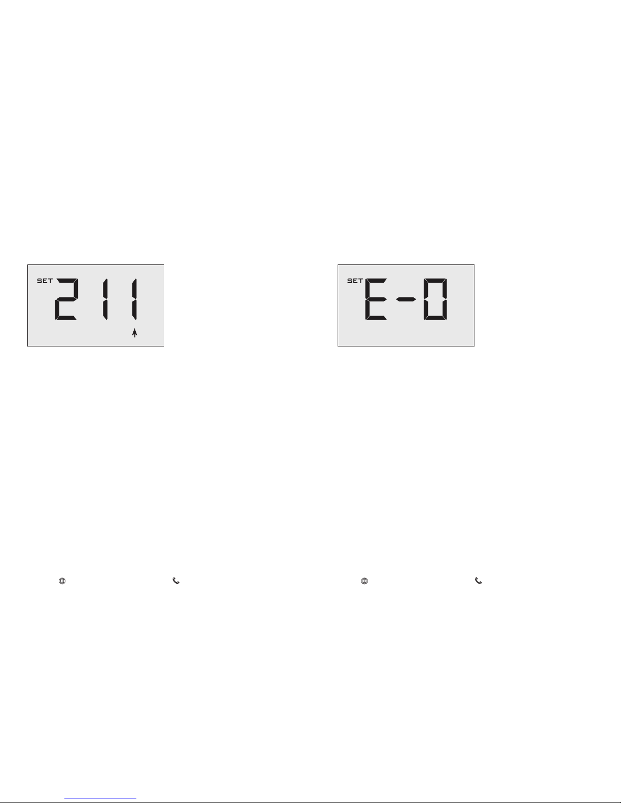
Configuring the Energy Saving Settings
➤ Use the “Up” and “Down” buttons to select the Energy Saving preset:
E-0* Energy Savings Off - No Temperature Setback;
E-1 Lowest Energy Savings;
E-2 Lower Energy Savings;
E-3 Standard Energy Savings;
E-4 Higher Energy Savings;
E-5 Highest Energy Savings;
Refer to the APPENDIX 1 for Energy Saving Preset details.
E-C Indicates “Custom Energy Savings Settings” in case the active
thermostat savings settings differ from any Energy Saving preset;
For details, refer to the “Custom Energy Savings Settings” section;
➤ Press the “Power” button to save the Thermostat Configuration and
start using the thermostat;
* Indicates default setting;
www.myamtex.com
800-650-3360
•
www.myamtex.com
800-650-3360
•
 Loading...