

Verdant VX-TW Installation Manual
VX-TW
VX Series Wireless Thermostat
with an Occupancy Sensor
INSTALLATION MANUAL
V.1 JUNE 26, 2017

3
Table of Contents
Introduction .................................................................................................4
Thermostat Installation ...............................................................................6
Pairing the Thermostat and the Control Card ............................................. 7
Installing the Wireless Control Card ............................................................8
Mounting the thermostat to the wall .........................................................9
Thermostat Configuration ......................................................................... 10
Setting the thermostat clock .......................................................................11
Entering the room number .........................................................................12
Configuring the Equipment Settings - Compressor Type ...........................13
Configuring the Equipment Settings - Electric Heat ..................................14
Configuring the Equipment Settings - Reversing Valve .............................15
Configuring the Energy Saving Settings ....................................................16
Testing the thermostat ...............................................................................17
Thermostat Maintenance ............................................................................18
Replacing Thermostat Batteries .................................................................18
Troubleshooting ..........................................................................................19
Error Codes ..................................................................................................19
Thermostat is not controlling the HVAC unit. .......................................... 20
APPENDIX 1 - Energy Saving Presets ...........................................................21
APPENDIX 2 - Glossary ................................................................................ 22
Warranty Information ................................................................................ 23
Technical Specifications ............................................................................. 24

4 5
Introduction
Verdant VX Series Energy Management Thermostats for the hospitality
industry deliver unprecedented energy savings without compromising
guest comfort.
An integrated occupancy sensor uses a combination of motion and
thermal sensing technologies for accurate occupancy detection.
Reliable occupancy detection allows for energy savings when rooms are
unoccupied.
Energy saving presets eliminate the guesswork and make it easy to
adjust the energy saving settings. (Patent Pending)
Fully configurable energy saving settings allow for customization of the
thermostat energy saving settings to fit any situation.
Large buttons with international symbols make it easy to adjust the
temperature in ±1° °F or °C and control the fan speed.
Comprehensive configuration options ensure full compatibility with
virtually any existing or emerging hospitality HVAC system with up to 2
heat and 1 cool stages.
Built-in wireless mesh-networking enables optional remote management.
NOTICE
FOR INSTALLATION OF NETWORKING THERMOSTATS WITH
REMOTE MANAGEMENT, REFER TO THE “VX-TW NETWORK
INSTALLATION” MANUAL.
LOGIN TO THE REMOTE MANAGEMENT WEBSITE TO CONFIRM
THE SERVER IS CONNECTED TO THE INTERNET BEFORE
INSTALLING THERMOSTATS.
DO NOT INSTALL THERMOSTATS IF THE SERVER IS NOT
CONNECTED TO THE INTERNET. STOP THE INSTALLATION AND
CONTACT VERDANT TECHNICAL SUPPORT.
START BY FIRST INSTALLING A THERMOSTAT IN THE ROOM
CLOSEST TO THE SERVER.
LOG IN TO VERDANT’S REMOTE MANAGEMENT WEBSITE
TO CONFIRM THAT THE THERMOSTAT IS ON THE REMOTE
MANAGEMENT WEBSITE WITH THE CORRECT ROOM NUMBER.
CONTINUE BY INSTALLING ADDITIONAL THERMOSTATS IN
ADJACENT ROOMS ONLY AFTER CONFIRMING THAT INSTALLED
THERMOSTAT(S) HAVE CONNECTED TO THE WIRELESS NETWORK
AND THE REMOTE MANAGEMENT WEBSITE .
IF INSTALLED THERMOSTAT(S) ARE NOT CONNECTING TO THE
NETWORK AND DO NOT APPEAR ON THE VERDANT’S REMOTE
MANAGEMENT WEBSITE WITH THE CORRECT ROOM NUMBER,
STOP THE INSTALLATION AND CONTACT VERDANT TECHNICAL
SUPPORT
THE ROOMS FURTHEST AWAY FROM THE SERVER SHOULD BE
INSTALLED LAST.
6 7
Before You Begin
➤ Determine the appropriate installation location for the thermostat.
➤ Set the HVAC unit to “External Thermostat” (Class 2) mode. Consult
the HVAC unit documentation to determine how to set the HVAC
unit to “External Thermostat” mode.
➤ Consult HVAC manufacturer’s documentation or use a voltmeter to
determine if the HVAC unit outputs AC or DC power (24V).
If the HVAC unit outputs AC power, make sure that the jumper
on the Wireless Control Card is in the AC position - jumper is
connecting “R” and “COM” pins (Default).
If the HVAC unit outputs DC power, make sure that the jumper
on the Wireless Control Card is in the DC position - jumper is
connecting “COM” and “C” pins.
THE THERMOSTAT SHOULD FACE THE BED AREA OF THE ROOM.
THE THERMOSTAT AND CONTROL CARD MUST NOT BE
INSTALLED NEAR OR ON METAL STRUCTURES OR SURFACES
INCLUDING METAL AIR DUCTING THAT MAY BE IN THE WALL.
WIRELESS CONTROLS CARDS MUST BE MOUNTED AWAY FROM
METAL AND METAL ENCLOSURES. VTAC INSTALLATIONS
SHOULD MOUNT THE CONTROL CARD ABOVE THE UNIT’S METAL
ENCLOSURE.
METAL STRUCTURES AND SURFACES SIGNIFICANTLY REDUCE
THE RANGE OF THE WIRELESS SIGNAL.
Before You Begin
Pairing the Thermostat and the Control Card
The Thermostat and Control Card must be paired in order to operate
together. Once paired, the thermostat cannot be used with another
wireless control card without repeating the pairing procedure.
In case of Network Installation with Remote Management, the
thermostat and the Control Card must be paired with a Network
Programmer specific to the property before the installation.
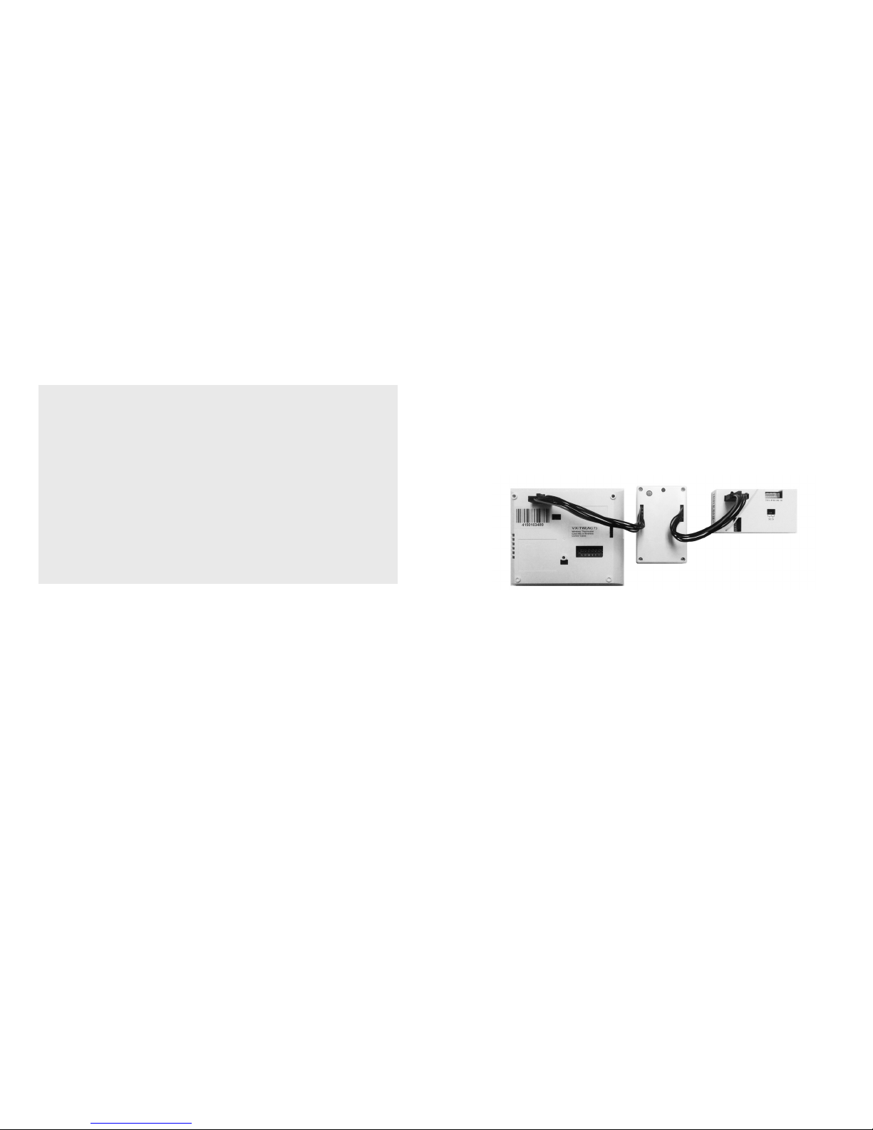
The Thermostat and Control Card must not be powered during the
pairing procedure - remove batteries from the thermostat and unplug the
control card from the HVAC unit during the pairing procedure.
➤ Plug one programmer connector into the thermostat;
➤ Plug the other programmer connector into the control card;
➤ Push the black button on the programmer. The red light on the
programmer should turn on and remain steadily lit;
If the red light on the programmer is blinking or is not steadily lit,
unplug the programmer from the thermostat and the control card
and repeat the steps above.
➤ Unplug the programmer from the thermostat and the control card;
 Loading...