

Verasys ZEC410 Installation Instructions Manual

Contents subject to change.
ZEC410 VAV Controllers
Installation Instructions
LC-ZEC410-xx
Refer to the QuickLIT website for the most up-to-date version of this document.
Applications
The ZEC410 VAV Controllers are compon ent s of the Verasys SMAR T equipment family. The VAV Zone controllers run
a pre-engineered HVAC zoning sequence and provide the inputs and outputs required for this application.
The ZEC Controller contains multiple features to ensure occupant comfort. Optional occupancy sensing capability
enables the ZEC controller to switch from occupied mode to standby mode based upon zone activity. Standby mode
maximizes energy savings by using setpoints that are higher and lower than occupied mode setpoints.
The ZEC410 controller also uses plug and play technology to detect which network sensor types are connected. See
the Accessories
You use the Verasys Smart Building Hub to set up the ZEC410 controller. The VAV controller commissioning is
performed with either the Smart Building Hub or the VAV Balancing Thermostat.
section to determine availability of additional sensing product information.
Part No. 24-10143-1264, Rev. –
Issued January 2017
IMPORTANT: Use this ZEC410 VAV controller only as an opera ting control. Whe re failure or malfunction of the
PEAK OEM controller could lead to personal injury or property damage to the controlled equipment or other
property, additional precautions must be designed into the control system. Incorporate and maintain other
devices, such as supervisory or alarm systems or safety or limit controls, intended to warn of or protect against
failure or malfunction of the ZEC410 VAV controller.
IMPORTANT : Utiliser ce ZEC410 VAV Controller uniquement en tant que dispositif de contrôle de
fonctionnement. Lorsqu'une défaillance ou un dysfonctionnement du controller risque de provoquer des
blessures ou d'endommager l'équipement contrôlé ou un autre équipement, la conception du système de
contrôle doit intégrer des dispositifs de protection supplémentaires. Veiller dans ce cas à intégrer de façon
permanente d'autres dispositifs, tels que des systèmes de supervision ou d'alarme, ou des dispositifs de
sécurité ou de limitation, ayant une fonction d'avertissement ou de protection en cas de défaillance ou de
dysfonctionnement du ZEC410 VAV controller.
North American Emissions Compliance
United States
This equipment has been tested and found to comply with the limits for a Class A digital device pursuant to
Part 15 of the FCC Rules. These limits are designed to provide reasonable protection against harmful
interference when this equipment is operated in a commercial environment. This equipment generates, uses,
and can radiate radio frequency energy and, if not installed and used in accordance with the instruction
manual, may cause harmful interference to radio communications. Operation of this equipment in a residen tia l
area may cause harmful interference, in which case users will be required to correct the interference at their
own expense.
Canada
This Class (A) digital apparatus meets all the requirements of the Canadian Interference-Causing Equipment
Regulations.
Cet appareil numérique de la Classe (A) respecte toutes les exigences du Règlement sur le matériel brouilleur
du Canada.
ZEC410 VAV Controllers Installation Instructions
1

Installation
Observe these guidelines when installing a ZEC controller:
• Transport the ZEC controller in th e original container to minimize vibration and shock damage to the ZEC
controller.
• Do not drop the ZEC controller or subject it to physical shock.
Parts Included
• one ZEC controller with removable FC and SA buses and power terminal blocks
• one self-drilling No. 10 x 25 mm (1 in.) screw
Materials and Special Tools Needed
• 6 mm (1/4 in.) female spade terminals for input and output wiring and crimping tool or spade mounted te rminal
blocks
• small straight-blade screwdriver for securing wires in the terminal blocks
• 8 mm (5/16 in.) wrench or 10 mm (3/8 in.) 12-point socket to tighten the square coupler bolt
• shims or washers to mount the ZEC, if necessary
• power screwdriver, 100 mm (4 in.) extension socket,
the ZEC
• pliers to open and close the damper
• 3.97 mm (5/32 in.) ID poly tubing
or a
punch, drill, and 3.5 mm (9/64 in.) drill bits to mount
Mounting
Observe these guidelines when mounting a ZEC:
IMPORTANT: When the air supply to the V AV box is below 10°C (50°F), make sure that any condensation on the
VAV box, particularly on the damper shaft, does not enter the ZEC electronics. Mount the ZEC vertically above
the damper shaft to allow any shaft
required in some installations.
• Ensure that the mounting surface can support the ZEC
• Mount the ZEC on a hard, even surface whenever possible.
• Use shims or washers to mount the ZEC securely and evenly on the mounting surface, if necessary.
• Mount the ZEC in an area free of corrosive vapors that matches the ambient conditions specified in the
Technical Specifications
• Provide suffici e nt spac e around the ZEC for cable and wire connections and adequate ventilation through the
controller (at least 50 mm [2 in.] on the top, bottom, sides, and front of the con trollers).
• Do not mount the ZEC in areas where electromagnetic emissions fr om othe r devices or wiring can interfere
with controller communication.
section.
condensation to fall away from the ZEC. Additional measures may be
and any user-supplied enclosure.
• Avoid mounting the ZEC on surfaces with excessive vibration.
On panel or enclosure mount applications, observe these additional guidelines:
• Do not install the ZEC in an airtight enclosure.
• Mount the ZEC so that the enclosure walls do no t obstruct cover removal or ventilatio n thro ugh the controll er .
• Mount the ZEC so that the power transformer and other devices do not radiate excessive heat to the co n troller.
ZEC410 VAV Controllers Installation Instructions
2
To mount th e ZE C co n tr ol l er s:
A
l
i
g
n
m
e
n
t
M
a
r
k
s
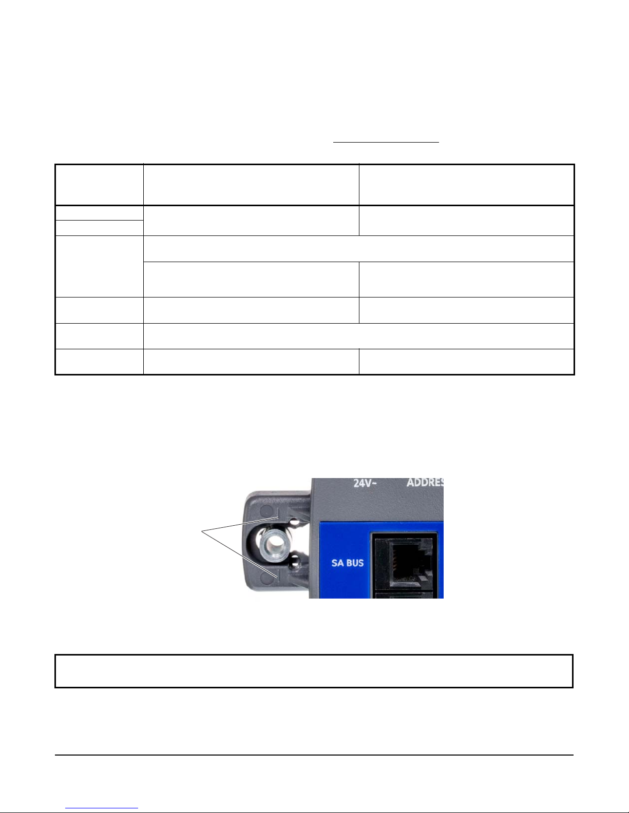
Figure 1: Captive Spacer Alignment Marks
1. Ensure that you have the appropriate personal protective equipment (PPE), such as a hard hat, safety glasses,
steel toe boots, and gloves.
2. Disconnect power from the controller transformer as well as the VAV box fan and heater circuits, if applicable .
3. Set all the switches on the field controller to their known settings, and then set the Master-Slave/T oken-Passing
(MS/TP) address, and ensure that EOL is set to Off. See Setup and Adjustments
.
Table 1: Verasys System Bus Controller Addressing
System Bus
Address/Range
Standalone Verasys System Bus
(not integrated into a BACnet BAS
Verasys System Bus
(integrated into a BACnet BAS network)
network)
1 May be used for Verasys system controllers Used for BACnet reserved function devices - not
2
3 Address used by an FC Bus or System Bus - connected to a Smart Building Hub - not used for Verasys
System Bus controllers or BACnet device address
May be used for Verasy s System Bus controllers if
there is not an FC Bus or System Bus connected
Smart Building Hub
4 May be used for Verasys System Bus controllers May be used for Verasys System Bus controllers if
117 Address used by the Smart Building Hub - not used for other Verasys System Bus controllers or BACnet
device address
118 through 127 May be used for Verasys System Bus controllers May be used for V erasys System Bus controllers if
used for Verasys System Bus controllers
May be used for Verasys System Bus controllers if
there is not an FC Bus or System Bus connected
there is a not a BACnet device address conflict
there is not a BACnet device address conflict
4. Place the ZEC controller in the proper mounting position on the actuator shaft so that the wiring connections
are easily accessible. Make sure the ZEC controller base is parallel to the VAV box (perpendicular to the
damper shaft). If needed, use a spacer to offset tipping of the ZEC controller caused by the shaft bushings.
Note: Use t he alig nment marks to cent er the ca ptive spacer to ensure sufficient ZEC movement in either direction
(Figure 8).
5. Secure the self-drilling No. 10 screw through the captive spacer with a power screwdriver and
100 mm (4 in.) extension socket. Otherwise, use a punch to mark the position of the shoulder washer,
and then
drill a hole into the VA V box using a 5/16 in. drill bit. Insert the mounting screw and tighten it against the spacer.
IMPORTANT: Do not overtighten the screw, or the threads may strip. If you mount the ZEC to the VAV box,
make sure tha t the screws do not interfere with damper blade movement.
6. Locate the damper position using the typ i cal mark ing on the end of the damper shaft.
ZEC410 VAV Controllers Installation Instructions
3
7. Note the direction, clockwise (CW) or counterclockwise (CCW), required to close the damper. The actuator
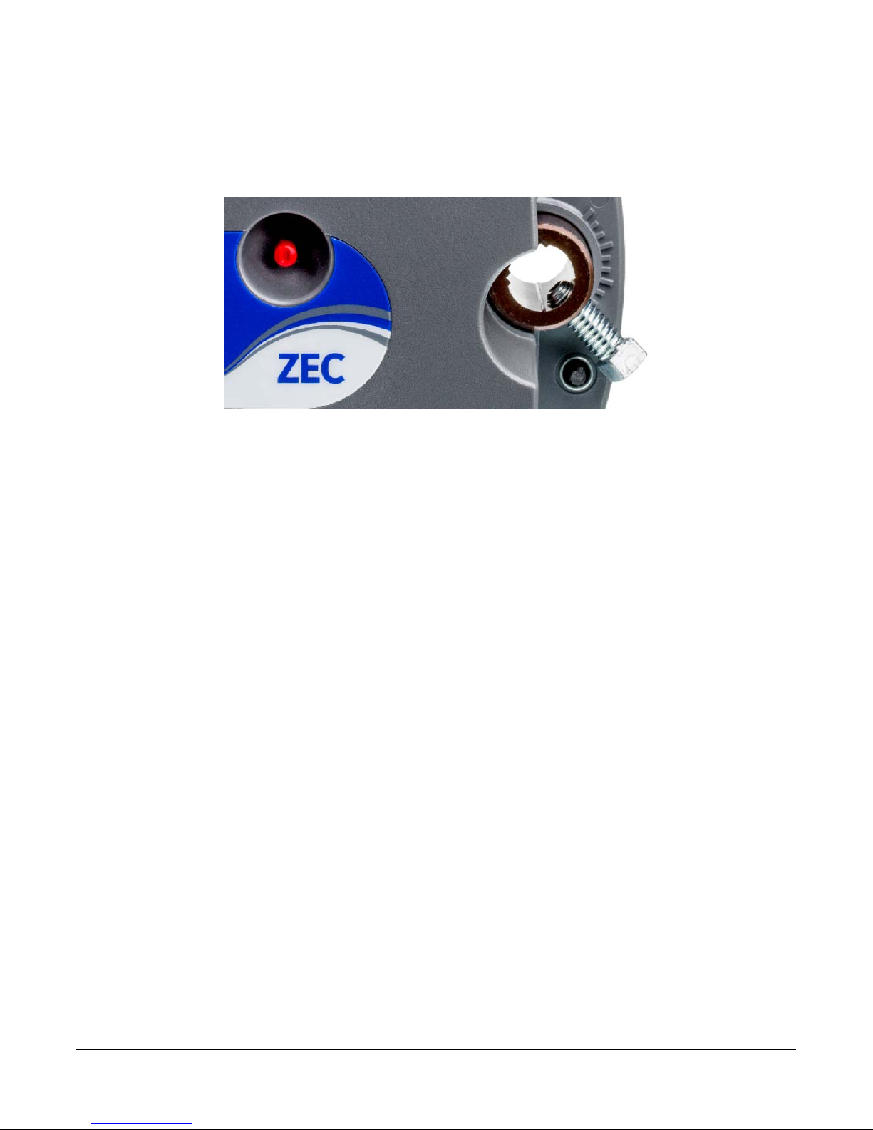
Figure 2: Manual Override and Coupler
setup depends on the necessary amount of rotation required for the damper to go from full-open to full-closed.
For 90° rotation, install the damper full-closed. For 45° or 60° rotation, install the damper full-open.
8. Push down and hold the Manual Override button and turn the ZEC controller coupler un ti l it contacts the
mechanical end-stop at either the full-closed or full-open position.
9. If the damper for a 45° or 60° box closes CCW , rotate the coupler to the CW mechanical limit. If the damper for
a 45° or 60° box closes CW, rotate the coupler to the CCW mechanical limit. This action sets the open end-
stop; the closed end-stop is set by the closed damper.
For 45° and 60° boxes, hard stop s must be provided at both full-closed and full-open damper positions. By
installing the ZEC controller at the full-open position, the ZEC controller provides the open stop for 45° and 60°
boxes. The closed damper seal provides the full-closed stop.
10. Tig hten the square coupler bolt to the shaft using an 8 mm (5/16 in.) wrench or 10 mm (3/8 in.) 12-point socket.
Tighten to 10.5 to 11. 5 N·m (95 to 105 lb·in).
11. Put a loop in the poly tubing, to trap condensation, when you attach the poly tubing to the ZEC pressure
transducer ports. Loop the poly tubing before you make the final connections.
12. Push the Manual Override button, and turn the actuator coupling manually to ensure that the actuator can
rotate from full-closed to full-open positions without binding.
13. Complete the mounting by rotating the damper to
the full-open position.
ZEC410 VAV Controllers Installation Instructions
4
Wiring
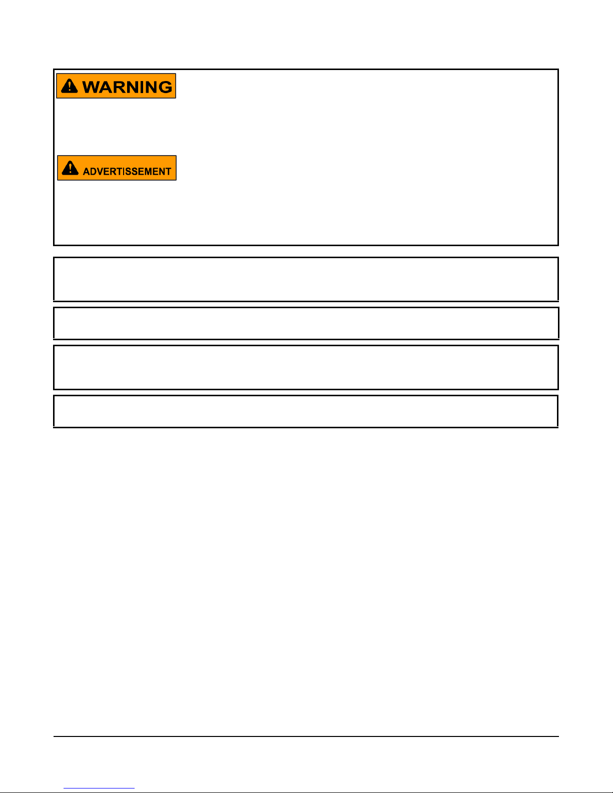
Risk of Electric Shock.
Disconnect power from the controller before making any adjustments. Do not touch any part of the printed circuit
board while power is applied. Failure to follow these precautions can result in personal injury or death.
Risque de décharge électrique.
Déconnecter l'alimentation du controller avant toute opération de réglage. Veiller à ne toucher aucune partie du
circuit imprimé lorsque celui-ci est sous tension. Le non-respect de ces précautions peut p rovoquer des blessur es
graves, voire mortelles.
IMPORTANT: Make all wiring connections in accordance with the Nati onal Electrical Code and local
regulations. Use proper electrostatic discharge (ESD) precautions during installation and servicing to avoid
damaging the electronic circuits of the controller.
IMPORTANT: Do not exceed the controller electrical ratings. Exceeding controller electrical ratings can result in
permanent damage to the controller and void any warranty.
IMPORTANT: Do not connect supply power to the controller before finishing wiring and checking all wiring
connections. Short circuits or improperly connected wires can result in damage to the controller and void any
warranty.
IMPORTANT: Use copper conductors only. Make all wiring in accordance with local, national, and regional
regulations.
Observe the following guidelines when wiring a ZEC controller.
Input and Output Terminals
See Figure 8 for an example of the staged control wiring. See Figure 9 for an example of the incremental control
wiring.
Sensor Actuator (SA) Bus Terminal Block
The SA Bus terminal block is a brown, removable 4-terminal plug, that is keyed to only fit into the board-mounted
brown SA bus.
ZEC410 VAV Controllers Installation Instructions
5
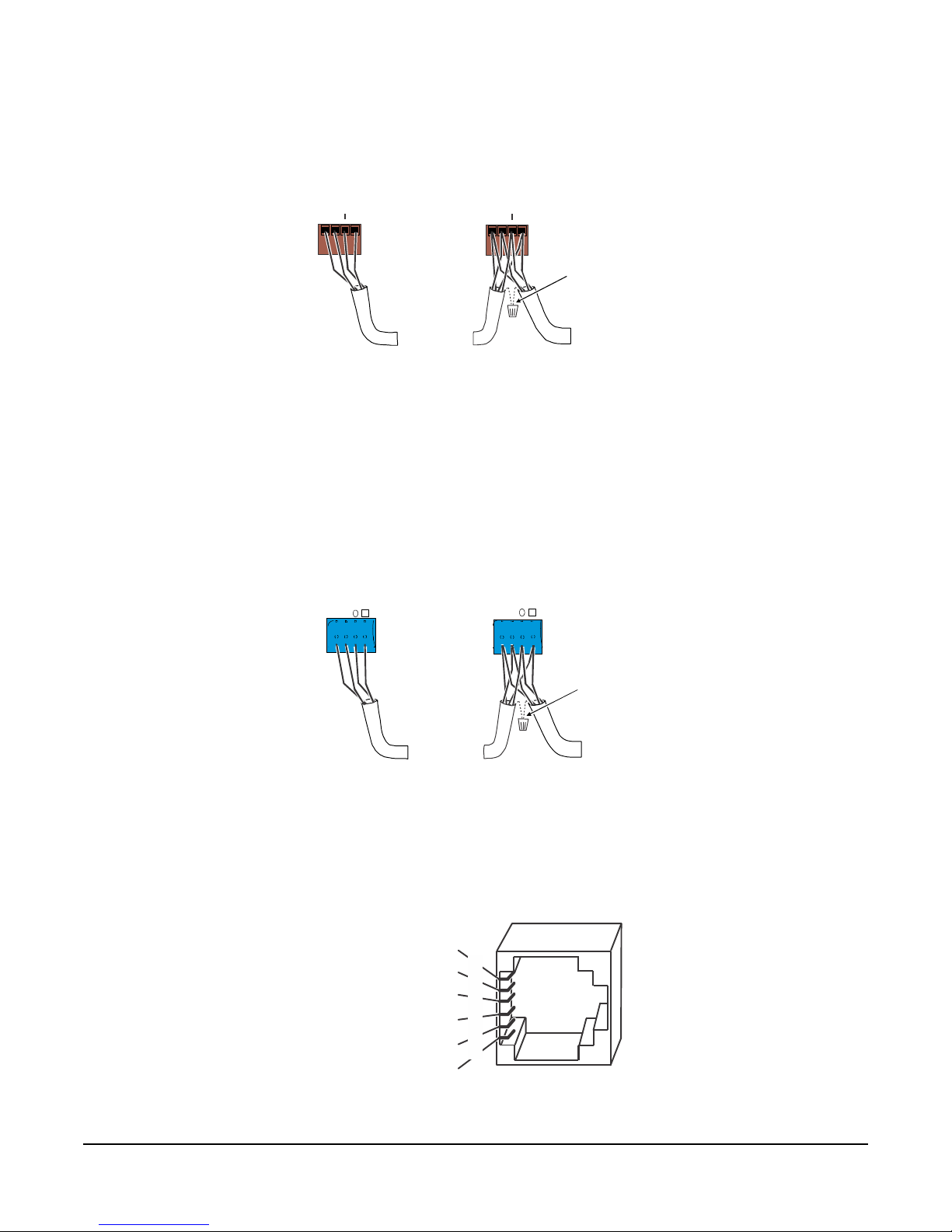
Wire the removable SA Bus terminal block plugs on the ZEC and other field devices in a daisy-chain configuration
Figure 3: SA Bus Terminal Block Wiring
Stranded, 4 - Wire (2 Twisted Pair) Shielded Cable
(One twi st ed pair is the and leads.
The secon d pair is COM an d SA PWR.)
+ -
Cable Shield
Connection
To Next
Device on
the SA Bus
FIG:sa_bus_spade
SA Bus
Spade Lu gs
Terminating Device
on SA Bus
on SA Bus
To Next
Device on
the SA Bus
+
CO
PW
Figure 4: FC Bus Terminal Block Wiring
Connection
To Next
Device on
FIG:sa_bus_spade
FC Bus
Spade Lu gs
on FC Bus
Daisy Chained Device
on FC Bus
To Next
Device on
Figure 5: Pin Number Assignments
SA and FC Bus Ports
Power (15 VDC)
SA or FC Bus
-
Power
(15 VDC)
F
I
G
:
r
j
1
2
_
p
i
n
o
u
t
2
3
4
5
6
1
using 4-wire twisted, shielded cable as shown in Figure 3.
Daisy Chained Device
R
M
COM
PWR
+
Field Controller (FC) Bus Terminal Block
The FC Bus terminal block is a blue, removable, 4-terminal plug that is keyed to only fit in to the board-moun ted,
blue FC Bus jack.
Wire the removable FC Bus terminal block plugs on the ZEC and other FC Bus controllers in a da isy-ch ain
configuration using 3-wire twisted, shielded cable, as shown in Figure 4.
Terminating Device
Modular Ports
The modular SA Bus and FC Bus ports on the face of the ZEC are RJ-12 (6-position) modular jacks.
The modular SA Bus ports provide a connection for the VAV
installations.
Bus and Power Common
Bus and Power Common
ZEC410 VAV Controllers Installation Instructions
-
+
SHIELD
COM
SA or FC Bus +
the FC Bus
-
+
COM
SHIELD
Cable Shield
the FC Bus
Balancing Too l. The FC Bus port is not used in ZEC
6
 Loading...