

Verasys LC-VAC300 0 Series Installation Instructions Manual
*2410143015
24-10143-01515, Rev —
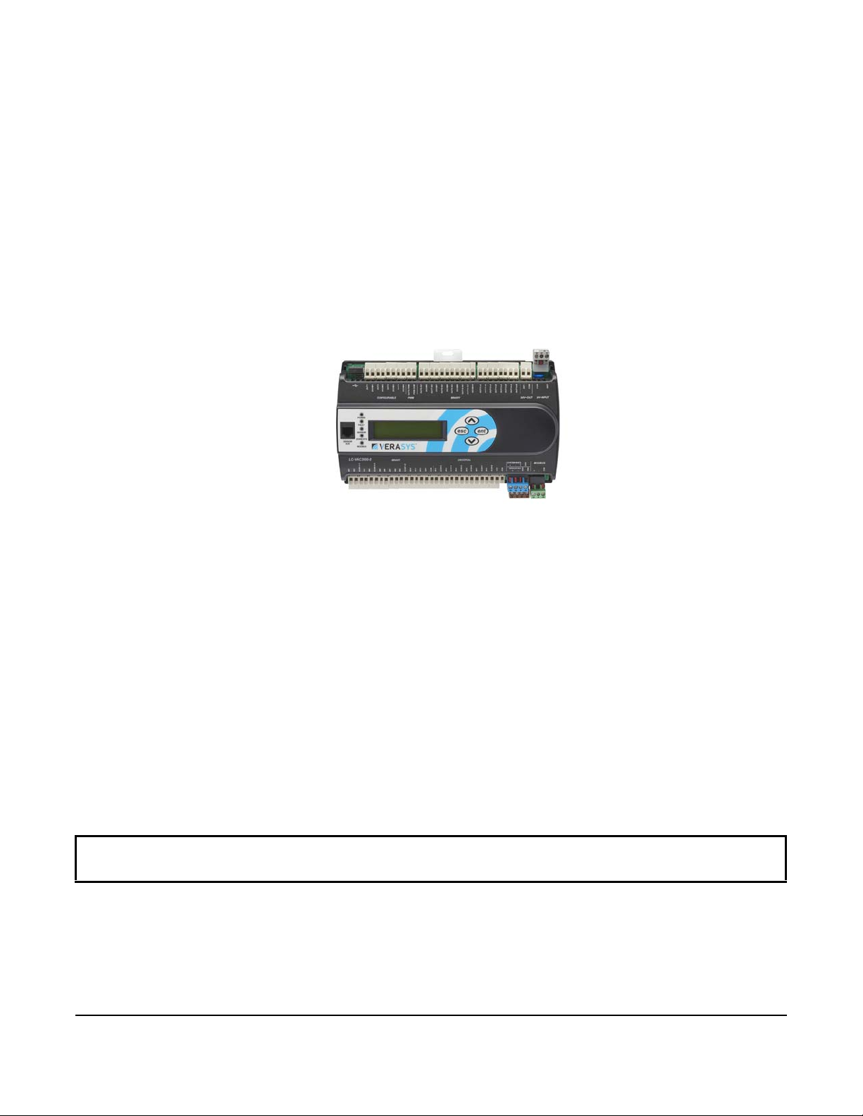
Verasys® 32 Point 24 VAC Application Controller
Installation Instructions
LC-VAC300x-0
Application
The Verasys® Application Controller is part of the SMART Equipment Controller family. The Verasys Application
Controllers run pre-engineered applications and provide the inputs and outputs required to monitor and control a
wide variety of HVAC equipment.
Verasys Application Controllers operate on an RS-485 BACnet® (MS/TP) Bus as BACnet Advanced Application
Controllers (B-AACs) and integrate into Johnson Controls® and third-party BACnet systems.
Verasys Application Controllers have an integral real-time clock. The clock functionality monitors and controls
schedules, calendars, trends, and operate for
the system network.
IMPORTANT: Use this Verasys Application Controller only as an operating control. Where failure or
malfunction of the Verasys Application Controller could lead to personal injury or property damage to the
controlled equipment or other property, additional precautions must be designed into the control system.
Incorporate and maintain other devices, such as supervisory or alarm systems or safety or limit controls,
intended to warn of or protect against failure or malfunction of the Verasys Application Controller.
extended periods of time as stand-alone controllers when o ffline from
Part No. 24-10143-01515, Rev A
Issued May 2018
IMPORTANT: Utiliser ce Verasys Application Controller uniquement en tant que dispositif de contrôle de
fonctionnement. Lorsqu'une défaillance ou un dysfonctionnement du controller risque de provoquer des
blessures ou d'endommager l'équipement contrôlé ou un autre équipement, la conception du système de
contrôle doit intégrer des dispositifs de protection supplémentaires. Veiller dans ce cas à intégrer de façon
permanente d'autres dispositifs, tels que des systèmes de supervision ou d'alarme, ou des dispositifs de
sécurité ou de limitation, ayant une fonction d'avertissement ou de protection en cas de défaillance ou de
dysfonctionnement du Verasys Application Controller.
V e rasys 32 Point 24VAC Application Controller Features
The Verasys Application Controllers are used in a Verasys system. The Verasys 32 Point 24 VAC Application
Controller comes without an application, but you can load custom built applications into this controller. Depending
on your market, you can access an application library in certain markets. Contact your local Verasys
representative. The Verasys 32 Point 240VAC Application Controller has the following features:
• Input/Output (I/O) quantities and characteristics of the Verasys Application Controller
• Real-time clock with local display
• Built-in BACnet schedule objects and calen da r s
• Mobile Access Portal (MAP) Gateway compatibility for configuration through smart mobile devices
connectivit
• Verasys Smart Building Hub ( S BH) compatible through the BACnet MSTP system bus connection
• Dedicated Sensor bus for Johnson Controls smart end-devices
• Dedicated Modbus port for third-party end-device integ ration with Modb
y
us
and remote
•
Multi-protocol support for BMS integration BACnet MSTP, N2 and Modbus RTU, through on-board display
Verasys® 32 Point 24 VAC Application Controller Installation Instructions
1
North American Emissions Compliance
United States
This equipment has been tested and found to comply with the limits for a Class A digital device pursuant to
Part 15 of the FCC Rules. These limits are designed to provide reasonable protection against harmful
interference when this equipment is operated in a commercial environment. This equipment generates, uses,
and can radiate radio frequency energy and, if not installed and used in accordance with th e instruction manua l,
may cause harmful interference to radio com munica tions. Op er ation o f this eq uip ment in a re sid ential a rea may
cause harmful interference, in which case users will be required to correct the interference at their own expense.
Canada
This Class (A) digital apparatus meets all the requirements of the Canadian Interference-Causing Equipment
Regulations.
Cet appareil numérique de la Classe (A) respecte toutes les exigences du Règlement sur le matériel brouilleur
du Canada.
Installation
Follow th ese guidelines when you install a Verasys Application Controller:
• To help
• V e r ify that all parts ship with the controlle r.
• Do not drop the controller or subject it to physical shock.
minimize vibration and shock damage, transport the controller in the original container.
Parts Included
• One Verasys 32 point 24V Application Controller
• One installation instruction sheet
Materials and Special To ols Needed
• Three fasteners appropriate for the mounting surface, such as M4 screws or #8 screws
• One 20 cm (8 in.) or longer piece of 35 mm DIN rail and appropriate hardware for DIN rail moun t only
• Small straight-blade screwdriver for securing wires in the terminal blocks
Mounting
IMPORTANT: Only qualified personnel should install or service Verasys products. These instructions are a
guide for such personnel. Mount the Verasys controllers on a wall or DIN rail inside an enclosure (rated at least
IP20). Carefully follow all instructions in this document and all instructions for the controller.
Follow these guidelines when you mount a field controller:
• Ensure the mounting surface can support the controll er , DIN rail, and any user-supplied enclosure.
• Mount the controller horizontally on 35 mm DIN rail whenever possible.
• Mount the controller in the proper mounting position, see Figure 1.
• Use shi ms or was hers to mount the cont rolle r secur ely and evenly on the mounting surface.
• Mount the controller in an area free of cor rosive va pors a nd fo llow the am bien t conditio n re quireme nts l isted in
Table 11.
• Ensure suffic ien t space around the con troller for
ventilation through the controller. Provide a minimum of 50 mm (2 in.) on the top, bottom, and front of the
controller.
Verasys® 32 Point 24 VAC Application Controller Installation Instructions
cable and wire connections for easy cover removal, and good
2
• Do not mount the controller on surfaces prone to vibration, such as duct work.
Horizontal Mount Position
Required for DIN Rail Mounting
• Do not mount the controller in areas where electromagnetic emissions from other devices or wiring can
interfere with controller communication.
Follow these additional guidelines when you mount a field controller in a panel or enclosure:
• Mount the controller so that the enclosure walls do not prevent cover remova l and obstruct ventilation throug h
the controller.
• Mount the controller so that the power tran sfo rmer and other devices do not radiate excessive heat to
controller.
• Do not install the controller in an airtight enclosure.
• Use a zip-tie to secure the controller when you ship it.
Figure 1: Verasys Application Controller mounting position
DIN Rail Mount Applications
Mounting the field controller horizontally on 35 mm DIN ra il is the preferred mounting method.
To mount a field controller on 35 mm DIN rail, complete the following steps:
the
1. Securely mount a 20 cm (8 in.) or longer section of
space so that the controller mounts as in in Figure 1.
2. Pull the two lower mounting clips outward from the controller to the extended position.
3. Hang the controller on the DIN rail by the hooks at
and position the controller snuggly against the DIN rail.
4. Zip tie the controller to the DIN rail when you ship.
5. Push the bottom mounting clips inward (up) to secure the controller on the DIN rail.
To remove the controller from the DIN rail, pull the bottom mounting clips out to the extended position and
carefully lift the controller off the DIN rail.
IMPORTANT: Do not overtighten the mounting screws. Overtightening the screws may damage the mounting
clips.
Verasys® 32 Point 24 VAC Application Controller Installation Instructions
a
35 mm DIN rail horizontally and centered in the appropriate
the top of the DIN rail channel on the back of the contr oller
3
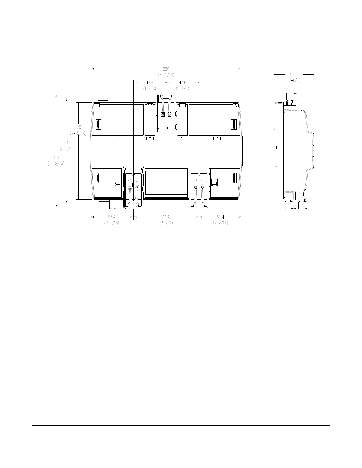
Figure 2: Back of Controller Showing Extended Mounting Clips, DIN Rail Channel, and Mounting
Dimensions, mm (in.)
Verasys® 32 Point 24 VAC Application Controller Installation Instructions
4
Wiring
Risk of Electric Shock.
Disconnect power from the controller before making any adjustments. Do not touch any part of the printed circuit
board while power is applied. Failure to follow these precautions can result in personal injury or death.
Risque de décharge électrique.
Déconnecter l'alimentation du controller avant toute opération de réglage. Veiller à ne toucher aucune partie du
circuit imprimé lorsque celui-ci est sous tension. Le non-respect de ces précautions peut p rovoquer des blessur es
graves, voire mortelles.
Risk of Electric Shock.
Disconnect or isolate all power supplies before making electrical connections. More than one disconnection or
isolation may be required to completely de-energize equipment. Contact with components carrying hazardous
voltage can cause electric shock and may result in severe personal injury or death.
Risque de décharge électrique.
Débrancher ou isoler toute alimentation avant de réaliser un branchement électrique. Plusieurs isolations et
débranchements sont peut-être nécessaires pou r -couper entière ment l'alimentation de l'équipement. Tout contact
avec des composants conducteurs de tensions dangereuses risque d'entraîner une décharge électrique et de
provoquer des blessures graves, voire mortelles.
IMPORTANT: Do not exceed the controller electrical ratings. Exceeding controller electrical ratings can result
in permanent damage to the controller and void any warranty.
IMPORTANT: Use copper conductors with a rating of at least 75°C (167°F). Make all wiring in accordan ce with
local, national, and regional regulations.
IMPORTANT: Electrostatic discharge can damage controller components. Use proper electrostatic discharge
precautions during installation, setup, and servicing to avoid damaging the controller.
For detailed information on configuring and wiring an MS/TP Bus, System Bus, and Sensor Bus, refer to the
Verasys® BACnet® MS/TP
Communications Bus T echnical Bulletin (LIT-12012362).
Verasys Appl ication Controller Terminal Blocks and Bus Ports
See Figure 11 for terminal block, spade location, and bus port locations on the LC-VAC300x-0 controller. Use the
following guidelines when wiring a controller.
Input and Output T e rm in al Blocks
On most field controller models, all of the input terminal blocks or spade terminals are mounted on the bottom of the
controller and the output terminal blocks and s p a d e t e r m i n a l s a re mounted on the top of the cont ro l le r. See Table 5
for more information about I/O
terminal functions, requirements, and ratings.
Verasys® 32 Point 24 VAC Application Controller Installation Instructions
5
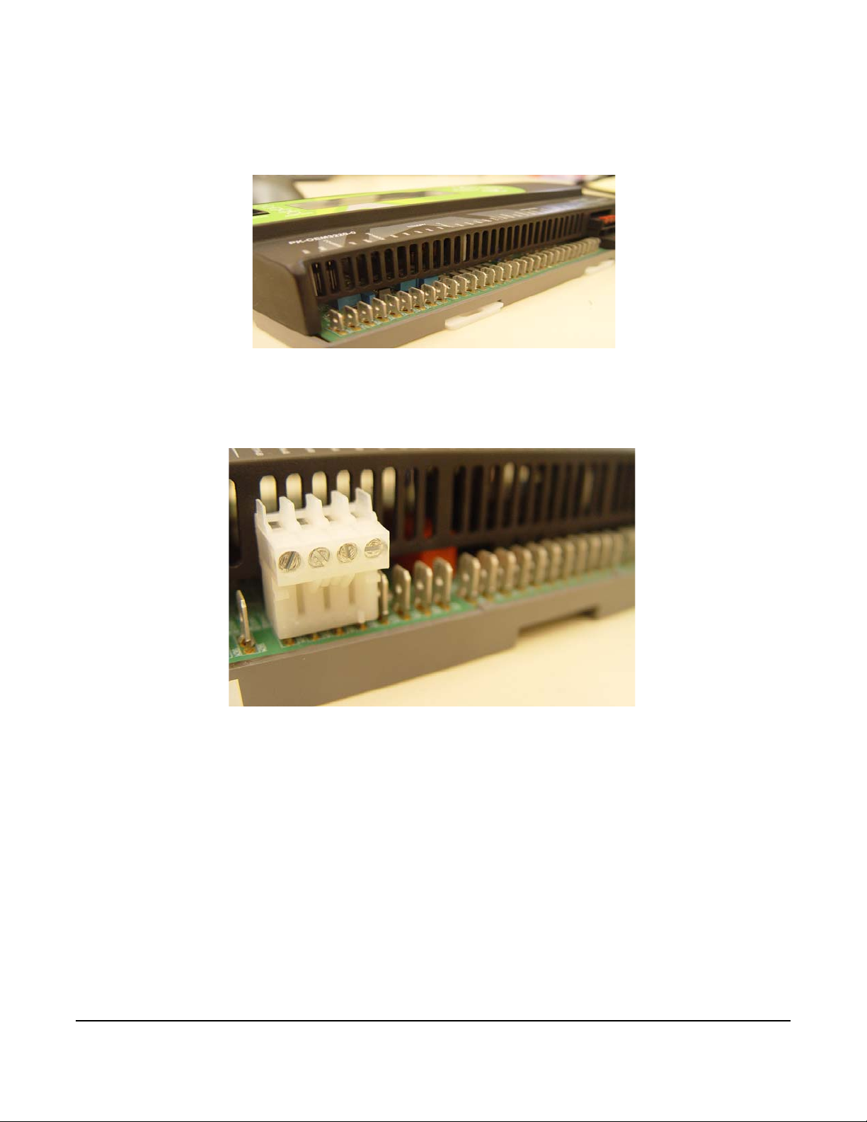
Factory Wiring
For all the I/O terminals listed in Table 5, use the correct gauge wiring. For each spade terminal in this application,
follow the guidelines in Table 5 and use a spade connector with screw terminals. Figure 3 shows
I/O spade terminals.
Figure 3: Verasys Application Controller Spade Terminals
Field Wiring
For all I/O terminals listed in Table 5, use the appropriate gauge wiring. For each spade ter minal in this appli cation,
follow the guidelines in Table 5 and use a spade connector with screw terminals.
Figure 4: Verasys Application Controller Spade Connector with Screw Terminals
Verasys® 32 Point 24 VAC Application Controller Installation Instructions
6
Stacked System and Sensor Bus Terminal Block
Stranded 3-Wire Twisted Shielded Cable
Isolated Shield
Connection
Terminal
To N ex t
Device on
the System Bus
Segment
System Bus
Terminal
Block Plugs
Terminating Device
on System Bus Segment
To N ex t
Device on
the System Bus
Segment
Daisy Chained Device
on System Bus Segment
SHD
+
COM
SHD
+
COM
A dual-stacked connector serves as the system bus and sensor bus port on the V erasys Controllers. The upper row
on the connector is the system bus port. The lower connector row is the sensor bus port.
Figure 5: Stacked System and Sensor Bus Terminal Block
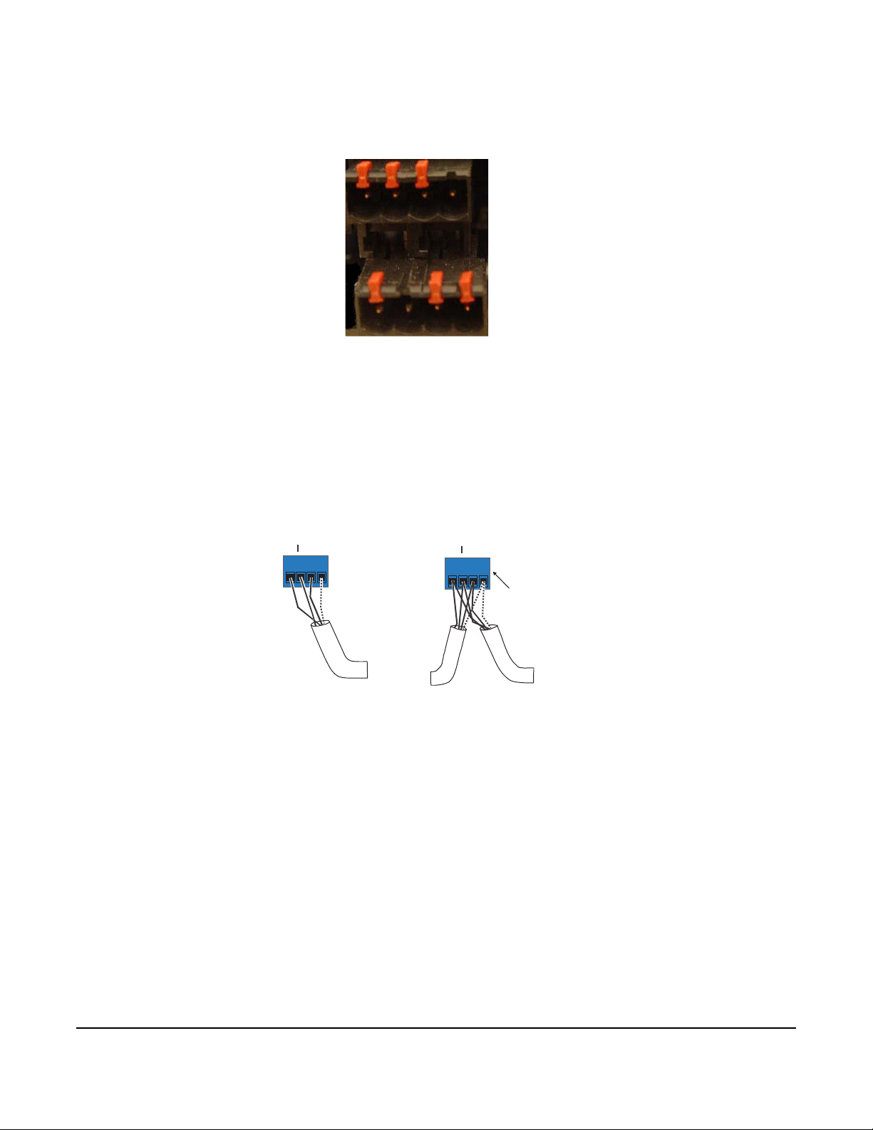
System Bus Te rminal Block
The System Bus terminal block is a blue, removable, 4-termin al pl ug that fits into a b oard -mounted jack. Wire the
removable system bus terminal block plugs on the controller on the top row of the stacked connector. Wire the other
field controllers in a daisy-chain configuration using 3-wire twisted, shielded cable, as shown in the following figure.
See Table 7 for more information on functions, ratings, requirements and cables.
Figure 6: System Bus Terminal Block Wiring
Note: The System Bus Shield (SHD) terminal is isolated and you can use it to connect the shields, in a daisy-
chain configuration for system bus wiring.
Sensor Bus Termin al Block
The Sensor Bus terminal block is a brown, removable, 4-terminal plug tha t fits in to a boar d-m ounted jack.
Verasys® 32 Point 24 VAC Application Controller Installation Instructions
7
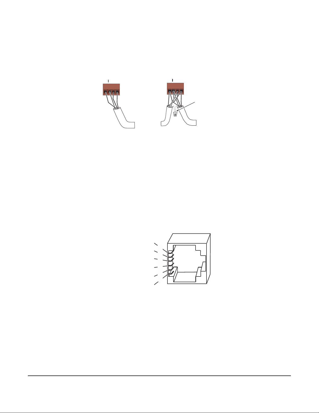
Wire the removable Sensor Bus terminal block plugs on the lower port of the Dual Stacked Connector to the
Stranded, 4-Wire (2 Twisted Pair) Shielded Cable
(One twisted pair is the and leads.
+ -
The second pair is COM and PWR.)
Cable Shield
Connection
To N e x t
Device on
th e Sensor Bu s
Sensor Bus
Terminal
Block Plugs
Terminating Device
on S ensor Bus
Daisy Chained Device
on S ensor Bus
To N e x t
Device on
th e Sensor Bu s
PWR
+
COM
PWR
+
COM
Power
(15 VDC)
Sensor Bus +
Sensor Bus
-
Bus and Power Common
Power
(15 VDC)
Sensor Bus Po rt
(RJ-12 Modular Jack)
Bus and Power Common
2
3
4
5
6
1
controller, and other Sensor bus devices in a daisy-chain configuration using 4-wire twisted, shielded cable as
shown in Figure 7. See Table 7 for more information on functions, ratings, requirements and cables.
Figure 7: Sensor Bus T e r minal Block Wiring
Note: The Sensor BUS PWR terminal supplies 15 VDC. You can use the PWR terminal to connect, in a daisy-
chain configuration, the 15 VDC power leads on the Sensor bus.
Sensor Bus Port
The Sensor Bus port on the middle left side of the controller (Figure 11) is an RJ-12, 6-position modular jack that
provides a connection for the SBH, the VAV Balancing Too l, specified network sensors, or other Sensor Bus devices
with RJ-12 plugs.
The Sensor port connects internally to the Sensor bus terminal block. See Table 7 for more information . The sen sor
bus port pin assignment is shown in Fi gure 8.
Figure 8: Pin Number Assignments for Sensor Bus Ports on Verasys Application Controllers
Modbus Terminal Block
The Modbus terminal block is a green, removable, 3-terminal plug that fits into a board-mounted jack.
Wire the removable Modbus terminal block plugs on the controller, and wire the other field controllers in a daisy-
chain configuration using 3-wire twisted, shielded cable as shown in Figure 9. See T able7 for more information on
functions, ratings, requirements and cables.
Verasys® 32 Point 24 VAC Application Controller Installation Instructions
8
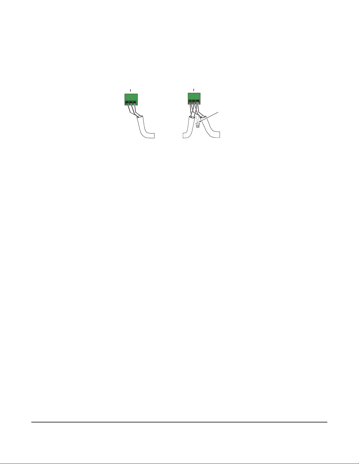
The Modbus port communicates as a Modbus device and connects to the Modbus network which can consist of
+
COM
Cable Shield
Connection
To N ex t
Device on
the Modbus
Segment
Modbus
Terminal
Block Plugs
Terminating Device
on Modbus
Daisy Chained Device
on Modbus
To N ex t
Device on
the Modbus
Segment
+
COM
one-to-many Modbus devices. Each Modbus device has a unique Modbus Re gister table and you must configur e it
within the application of the Verasys Controller.
Figure 9: Modbus Terminal Block
Verasys® 32 Point 24 VAC Application Controller Installation Instructions
9
 Loading...