

Verasys LC-VAC3000-0 Quick Start Manual
Verasys Chilled Water System Controller
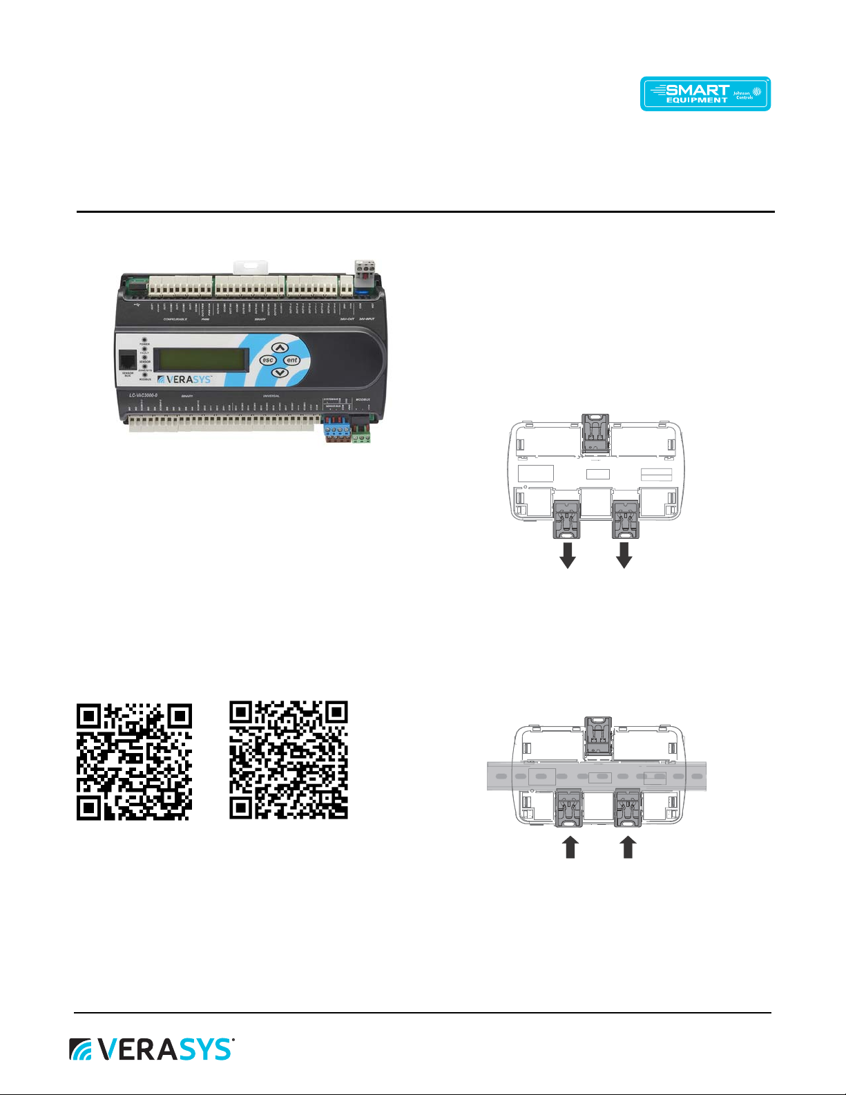
Figure 2: Pull lower mounting clips down
Figure 3: Pull lower mounting clips down
Quick Start Guide
LC-VAC3000-0
Refer to the QuickLIT website for the most up-to-date version of this document.
Figure 1: LC-VAC3000-0
About this guide
Mounting the controller
To mount the controller, complete the following steps:
1. Mount a 20 cm (8 in.) section of
horizontally.
Note: Mount the controller in the horizontal position.
2. On the back of the controller, extend the two mounting clips as
shown in the following figure.
Code No. Lit 12013229
Issued April 2019
35 mm (1.3 in.) DIN rail
This quick start guide provides the basic information you need to
configure and install the Chilled Water System Controller and
application.
For further information, refer to the Verasys® 32 Point 24 VAC
Application Controller Installation Instructions (24-10143-01515), and
Verasys Chilled Water System Controller Application Note (LIT-
12013173) on QuickLit.
For more information or to access Quicklit, scan the following QR
codes:
LC-VAC3000-0 QR code QuickLit QR code
3. Place the controller on the DIN rail.
4. To secure the controller on the DIN rail, push the bottom
mounting clips up as shown in the following figure.
5. To remove the controller from the DIN rail, pull the bottom
mounting clips out to the extended position and carefully lift the
controller off the DIN rail
Verasys Chilled Water System Controller Quick Start Guide
1
Wiring the controller
+
COM
SHD
1
2
3
4
4
+
COM
SHD
+
COM
SHD
(COM)(24 VAC)
HOT
COM
24V~
HOT
COM
1
2
3
The system bus terminal block is a blue, removable, 4-terminal plug
that fits into a board-mounted jack. To wire the controller, complete
the following steps:
1. Wire the removable system bus terminal block as shown in
Figure .
2. Wire any other devices that you want to connect on the system
bus in a daisy-chain configuration using 3-wire twisted, shielded
cable as shown in Figure 5.
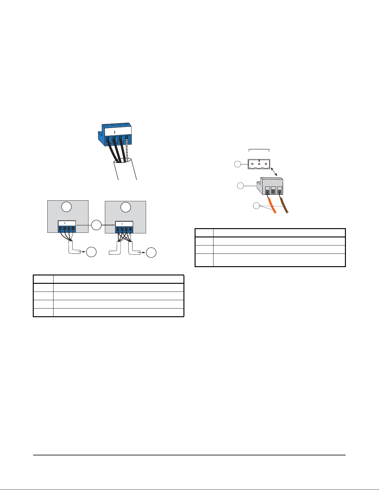
Figure 4: System bus terminal block wiring
Figure 5: Daisy-chain wiring configuration
2. Turn the EOL switch on by moving the white switch to the right.
Wiring the supply power termi na l block
The 24 VAC supply power terminal block is a gray, removable, 3terminal plug that fits into a board-mounted jack on the top right of the
controller.
Wire the 24 VAC supply power wires from the transformer to the HOT
and COM terminals on the terminal plug, as shown in Figure 6.
Note: Do not use the middle terminal on the supply power
terminal block.
Note: The supply power wire colors may be different on
transformers from other manufacturers. Refer to the transformer
manufacturer’s instructions and the project installation drawings for
wiring details.
Figure 6: Supply power terminal block wiring
Table 1: Daisy-chain wiring configuration
No. Description
1 Terminating device on the system bus
2 System bus terminal block plugs
3 Daisy chained device on a system bus segment
4 To next device on the system bus segment
Enable the end of line (EOL) switch
If the controller is at the beginning or end of the line on the system
communication bus, you must activate the EOL switch.
1. To disengage and remove the plastic cover press down on the top
of the controller.
Note: Ensure that you do not disconnect the ribbon cable that
connects the controller to the board display.
Note: The EOL switch is a red block with a white switch located
directly above the system bus terminal block.
Table 2: Supply power terminal block wiring
No. Description
1 Supply power terminal block jack
2 Supply power terminal block plug
3 Wires from Johnson Controls® 90 VAC to 24 VAC, Class 2
power transformer
Wiring options
Configurable outputs 1, 2, and 3, and triac binary outputs 8 and 9 are
rated for a maximum current draw of 0.5 A. It is best practice to use
pilot relays when you use these outputs to drive lighting contactors.
Y ou can choose a pilot relay with a manual override function. Y ou can
also use software to reverse the polarity of the output. This means
that you can drive contactors with contacts that are normally open
(fail off) or normally closed (fail on).
Note: See Figure 7 for information about wiring the Chilled Water
System controller.
Verasys Chilled Water System Controller Quick Start Guide
2
 Loading...