


Vera Audio
Power Amplifier
P400/1000
Instruction manual and specifications

Important Safety Instructions
1. Read these instructions.
2. Keep these instructions.
3. Heed all warnings.
4. Follow all instructions.
5. Do not use the product near water.
6. Cleaning. Unplug this product from the wall outlet before cleaning. The anodized cabinet can
tolerate almost any cleaning agents including isopropanol, alcohol and acetone. But for normal
cleaning regular dish soap is sufficient. Wipe dry with a micro fiber cloth.
7. Do not block the ventilation holes (bottom) and the fan inlets. If you install the apparatus in a
built-in installation, such as a bookcase or rack, ensure that there is adequate ventilation.
8. Do not install near any heat sources such as radiators, heat registers, stoves, or other apparatus
that produce heat.
9. Do not defeat the safety purpose of the grounding-type plug. For your safety, the amplifier should
be connected to a grounded power outlet.
10. Protect the power cord from being walked on or pinched particularly at plugs, convenience
receptacles, and the point where they exit from the apparatus.
11. Do not place this product on an unstable cart, stand, tripod, bracket, or table. The product may
fall, causing serious injury to a child or adult, and serious damage to the product. Use only with a
cart, stand, tripod, bracket, or table recommended by the manufacturer, or sold with the product.
Any mounting of the product should follow the manufacturer’s instructions and should use a
mounting accessory recommended by the manufacturer.
12. Unplug this apparatus during lightning storms or when unused for long periods of time.
13. Refer all servicing to qualified service personnel. Servicing is required when the apparatus has
been damaged in any way, such as power-supply cord or plug is damaged, liquid has been spilled or
objects have fallen into the apparatus, the apparatus has been exposed to rain or moisture, does not
operate normally, or has been dropped.
15. Damage Requiring Service. Unplug the apparatus from the wall outlet and refer servicing to
qualified service personnel under the following conditions:
A. If liquid has been spilled, or objects have fallen into the apparatus,
B. If the apparatus has been exposed to rain or water,
C. If the apparatus does not operate normally by following the operating instructions. Adjust
only those controls that are covered by the operating instructions as an improper adjustment
of other controls may result in damage and will often require extensive work by a qualified
technician to restore the apparatus to its normal operation,
D. If the apparatus has been dropped or damaged in any way, and

E. When the apparatus exhibits a distinct change in performance, this indicates a need for
service.
16. Object and Liquid Entry. Never push objects of any kind into the apparatus through openings as
they may touch dangerous voltage points or short-out parts that could result in a fire or electric
shock. The apparatus shall not be exposed to dripping or splashing and no objects filled with liquids,
such as vases shall be placed on the apparatus. Don’t put candles or other burning objects on top of
this unit.
17. When replacement parts are required, be sure the service technician has used replacement parts
specified by the manufacturer or have the same characteristics as the original part. Unauthorized
substitutions may result in fire, electric shock, or other hazards.
WARNING: TO REDUCE THE RISK OF FIRE OR ELECTRIC SHOCK, DO NOT EXPOSE THIS APPARATUS TO
RAIN OR MOISTURE.
NOTES ON ENVIRONMENTAL PROTECTION
At the end of its useful life, this product must not be disposed of with regular
household waste but must be returned to a collection point for the recycling of
electrical and electronic equipment. Your local administrative office can advise you
of the responsible waste disposal point.
Introduction
Opening the box
Supplied Accessories
Set up
Thank you for purchasing the Vera Audio P400/1000. We have strived to design and build a power
amplifier with very low noise, high output power combined with extremely low distortion, multiple
practical functions, high security, a build quality that will ensure a long life span, and with a nice
looking chassis. We sincerely hope you will be satisfied with the product.
The P400/1000 comes in two cardboard boxes in order to ensure safe transport. The easiest way to
remove the unit is by turning the boxes upside down and lift off the boxes. That way, the amplifier
will be resting on protective foam which can be removed at the end.
Packed with your P400/1000 you will find:
One detachable mains power cord, 1.5 m length in 3x1.5mm² dimension.
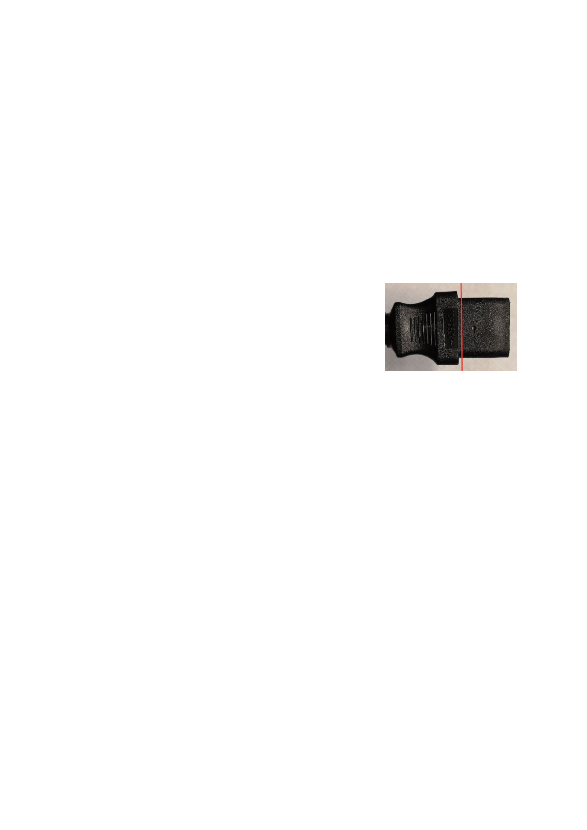
Power
Attach the power cord. Make sure it’s properly in place. The supplied
power cable shall go as far in as the red line in the picture. The
amplifier must only be connected to a 230V grid. The device is
protected with a 10A fuse.
Cooling and placement
The P400/1000 has air vents on the sides for fans. The air escapes through openings underneath at
the front of the cabinet. Allow a minimum of 3 cm free air passage on both sides and ensure that the
holes on the bottom are not blocked to allow for proper air ventilation.

Connections
Balanced XLR inputs
• Use XLR cables for external sources that are equipped with balanced audio output.
• If your external source only has RCA outputs, we recommend using an RCA male to XLR male cable.
• In bridge mode, the right XLR input is the only one being used.
• PIN CONFIGURATION OF BALANCED XLR JACK:
Pin 1 is connected to the chassis (ground).
Pin 2 is connected to positive.
Pin 3 is connected to negative.
For optimal RF protection the XLR’s metal button is also connected to
the chassis as shown by the picture to the right.
Speaker terminals
• P400/1000 is equipped with gold-plated, color-coded speaker terminals.
• Connect RIGHT SPEAKERS and LEFT SPEAKERS terminals to corresponding speakers. Make sure the
“+” (red) terminal and “-” (white) terminal are connected to the corresponding “+” and “-” terminals
of the speaker. Use extra care to ensure that no stray wires or strands cross between posts or
terminals at either end.
• Both spades and banana plugs are accepted. Stripped cables up to 6 mm
2
can be used.
• None of the four terminals shall be connected together or connected to ground. Only speakers are
to be connected.
Trigger input
• The 12V trigger input allows the P400/1000 to be switched remotely from standby to operating
mode and vice-versa from an auxiliary equipment such as a DAC, preamplifier, AV processor, etc.
• To enable the trigger function, insert a mini jack into the 12V Trigger input connector on the back
of the amplifier. The amplifier can now be turned on and off remotely with a voltage between 3.5V
and 24V. The trigger voltage must be present continuously for the amplifier to stay on. When the

voltage drops to under 3V it will shut down.
Settings
It is possible to override the trigger input, both turning on and off the amplifier using the front panel
button even if the trigger mini jack is inserted.
• To avoid any unwanted interference from other equipment, the trigger input is completely isolated
from the amplifier’s audio circuits with an optocoupler. This isolation also includes the amplifiers
ground system.
• Both stereo and mono mini jack (TS) plugs can be used. It is only important that the tip is positive.
Reverse polarity will not harm the trigger input, it will simply not work.
• Trigger voltage and current:
Nominal voltage is 12V. It will draw 4mA @ 12V.
Minimum voltage is 3.5V. It will draw 0.3mA @ 3.5V
Maximum voltage is 24V. It will draw 9.5mA @ 24V
Stereo/Bridged
• Stereo mode enables two channels. The signal that comes from the left input
amplifies and is sent to the left output. The same for the right channel.
• Bridge mode enables mono channel with increased output power. When the
switch is set to bridge the signal from the right XLR input will drive the two middle
speaker terminals (marked with bridged output). The outer speaker terminals shall
not be used in this configuration. The left XLR input is disabled when the switch is
set to bridge.
• It’s not recommended to use bridge mode with speakers that have a lower impedance than 3 ohm.
Bi-amping would then be a better option.
Bi-amping
Bridge function can also be useful in a set up where bi-amping is used. While the left XLR input is
deactivated, all the four speaker terminals are still active running from the right XLR input. This can
be used in several configurations. One example would be to connect the woofer system to the left
speaker terminals and midrange/tweeter to the right speaker terminals. In this setup, the right and
left outputs will have the same output power as in stereo mode.

Gain switches/amplification
• Left and right channels have independent amplification. It’s adjusted in 3 dB
steps (some early models has two steps with 4 dB increments) from 12 dB to 30
dB.
• The better gain setting depends on the source and how much power the
speakers can handle. Generally, the best signal/noise ratio will be achieved with
lower gain. A good starting point is setting the gain to 18 dB and increase it later
if there’s a need for more output.
• It’s possible to adjust the gain when the amplifier is being used. Only a very small “pop” will be
heard.
• In bridge mode the amplification will be doubled, and one needs to add 6 dB to the written values.
For example when both switches are set to 12 dB, the amplification becomes 18 dB.
Normally both switches will be set to the same which will load the two amplifier channels equally.
However, it’s possible to fine tune the gain by setting one with a step above the other. For example,
if the left switch is set to 12 dB and the right to 15 dB, one will get
+ 6 = 19.5 dB.
• If the amplifier is to be used with bi-amping where e.g. the woofer is connected to the left speaker
terminal and midrange/tweeter to the right speaker terminal one should use the same gain for both
switches in order to get equal level.
• It’s possible to turn the switch one step below 12 dB. This will mute the respective channel.
Power Switch
• The AC mains power to P400/1000 is regulated by the power switch. When the power switch is set
to “1” position, the unit goes to standby mode as shown by the orange status condition of the LED
indicator.
• If you intend not to use the unit for long periods of time (such as when on vacation), switch off the
power switch by setting it to position “0”.
Fuse holder
• If necessary the fuse can be replaced. The value of the fuse being used should be 10A slow blow.
Trigger LED light
• When the trigger input is being used, the LED beside the trigger input turns on with green light.

Usage
Front Panel
1. Standby button
• When the rear power button is activated the P400/1000 will start in standby mode. The amplifier
will then consume very little energy at 0.25W and the LED light will be orange. The large internal
power supply and output stages will be completely turned off.
• By pressing the standby button, the amplifier powers up from standby mode. The LED light will be
purple for about 7 seconds and after that a white LED light indicates that’s the amplifier is in normal
operating mode.
• When the P400/1000 is turned on the input signal should be low. A high input signal can in some
cases trigger the internal protection circuits as the amplifier turns on and will shut down the output
immediately. This is indicated by a permanent red or green LED light, depending on which channel
has been turned off. If this happens, the input signal needs to be lowered and the P400/1000
restarted.
• Press the standby button again to switch the unit to standby mode (indicated by orange LED light).
This can also be done when there’s a need to restart the amplifier due to an error like too high input
signal.
Operation
• Under normal operation the P400/1000 will get moderately warm. If the amplifier is pushed hard
(over approximately 300W continuously), or is placed in a hot environment over 30c the internal fans
will start in order to keep the internal temperature down. With normal operating conditions and
temperatures, the fans will remain inactive.
• When the amplifier isn’t being used, it’s recommended to turn it off. There is no performance gain
by leaving the P400/1000 on continuously. The very low distortion is present already seconds after
it’s turned on and turning the amplifier off when not being used will extend the life span. If the
P400/1000 isn’t turned off after 48 hours from when it was turned on, the fans will be activated to
ensure a low temperature on the internal capacitors. The fans will operate with a very low speed of
only 400-500 RPM and a decibel level below 0 dB and thus not be audible.

2. LED light
• White light indicates power on.
• Orange light indicates amplifier being in standby mode.
Error messages from LED are as follows:
• Blue/yellow/green blinking with time interval as the picture.
Indicates that one (or both) fans have failed. The error is indicated
only if the fans should have been active.
• Green blink. If the right channel is clipping because of too high voltage it will
be indicated by short green blinks. The blinking rate will depend on the music
signal. However, there will always be a minimum of 0.1s blink if clipping has
occurred in order to make sure that even short clipping in the high frequencies
is being brought to the user’s attention.
• Green/blue blink. If there’s an additional blue blink right after a
green blink it indicates that the power on the output has passed 24A
and the clipping is caused by this. This happens if the load has too low
impedance.
• Red blink and red/blue blink with the same pattern as above is the same information but for the
left channel.
Fan filter
• The fans are equipped with filters to avoid dust from gathering inside the
amplifier. In hot environments or if the P400/1000 isn’t being turned off these
should be checked occasionally.
• If much dust has been accumulated the filters can be removed and cleaned.
• The filter is magnetically attached and at the top of the filter there’s a small
notch where one can stick a binder or thin gear and push it out. The filter can be
blown clean from the inside out. If there’s accumulated fat the filter can also be washed with
warm water and a mild detergent. Let the filter dry completely before it’s installed.
For the magnetic filter to attach properly to the receiving magnet, make sure the small notch points
upward when re-attaching the filter.

SPECIFICATIONS
Technical data is measured with 240V current on 10 random units. Minimum values are stated.
Output impedance (20-20kHz) < 5mΩ
Input impedance 47kΩ
Noise () < 15uV
Frequency response DC-20kHz = +0 to -0.5dB
Signal-to-Noise Ratio stereo > 130dB
Signal-to-Noise Ratio bridged >132dB
Damping factor > 1600 with 8Ω speakers
Standby power 0.25W
Power
Stereo, both channels driven at 8Ω
400W with maximum 1% THD+N
330W with maximum 0.01% THD+N
300W with maximum 0.004% THD+N
Stereo, both channels driven at 4Ω
750W with maximum 1% THD+N
620W with maximum 0.01% THD+N
550W with maximum 0.004% THD+N
Bridged 8Ω
1500W with maximum 1% THD+N
1100W with maximum 0.01% THD+N
800W with maximum 0.004% THD+N
Sensitivity
Describes current on input to maximum before clipping (1% THD). This depends on the gain settings.
Maximum input voltage is 10,3V RMS before the input stages will clip the signal (+22.5dBu)
Gain Sensitivity
12dB (3,98x) 14V (Note the 10,2V RMS maximum input voltage in this setting)
15dB (5,62x) 10V
18dB (7,94x) 7V
21dB (11,22x) 5V
24dB (15,85x) 3,6V
27dB (22,39x) 2,5V
30dB (31,62x) 1,8V
An example of how to calculate the output power on an 8Ω speaker if the signal is 2V and the gain is
set to 24 dB.
2V on the input will produce a 2V*15.85=31.7V on the output. With a 8 Ohm speaker this will
generate 31.7*31.7/8 = 125W of power.
31.7V on the output will give the following power on an 8Ω speaker:
,
= 125.
This is well below the limit of clipping, hence one can increase the gain to 27dB without the amplifier
clipping if the signal in is maximum 2V.

DIMENSION AND WEIGHT
Net dimension
Width 29 cm
Depth (including terminals) 38 cm
Height 8.2 cm
Weight 9 kg
Shipping dimension
Width 47 cm
Depth 36 cm
Height 16 cm
Shipping weight 9.8 kg
 Loading...