

Veolia HYDROTECH 20 Series, HDF 12 Series, HDF 1602-1F, HDF 20 Series, HYDROTECH 24 Series Operation And Maintenance Manual
...
Drumfilter HDF - 12/16/20/24 -series
Operation and maintenance manual
Revised:2019-03-19

Operation & maintenance manual, Drum filter HDF 12/16/20/24 -series
LIST OF CONTENTS
1. INTRODUCTION 5
2. SAFETY INSTRUCTIONS 6
2.1 Warning symbols 6
2.2 CE marking 6
2.3 Conversion 6
2.4 Personnel requirements 7
2.5 Emergency stop 7
2.6 Electrical safety 7
2.7 Safety instructions 7
3.1 Overview 9
3.2 Identifying the filter 11
4. RECEPTION AND HANDLING 12
4.1 Reception 12
4.2 Storage 12
4.3 Liing the equipment 12
5. GENERAL INSTALLATION INSTRUCTIONS 13
5.1 Installation site 13
5.1.1 Outdoor installation 13
5.1.2 Foundations 13
5.2 Emergency overflow 13
5.3 Electrical connection 14
5.4 Equipotential bonding 14
5.5 Checking drum rotation 14
2

Operation & maintenance manual, Drum filter HDF 12/16/20/24 -series
5.6 Pipe connections 14
5.7 Backwash system 14
5.8 Filter placement 14
6. START-UP AND OPERATION 15
6.1 Check procedures during start-up 15
6.2 Automatic seings 16
6.2.1 Level dierences 17
6.2.2 Operating mode HAND – continuous rotation/washing 18
6.2.3 Operating mode AUTO – automatic level control 18
6.2.4 Adjusting the level sensor 18
6.2.5 Adjusting delay time 18
6.2.6 Seing the level relay 18
6.3 Backwash system 19
6.4 Retightening bolts 19
7. FUNCTION 20
7.1 Intended use 20
7.2 Non-intended use 20
7.3 Filtration and backwash process 20
8. MAINTENANCE/SERVICE 21
8.1 Backwash system 21
8.1.1 Servicing conventional nozzles 21
8.1.2 Self-cleaning nozzle 22
8.2 Wash water filter 24
8.3 Bearings 25
8.3.1 Lubrication 25
3

Operation & maintenance manual, Drum filter HDF 12/16/20/24 -series
8.3.2 Checking centre bearings for wear 25
8.4 Filter element 26
8.4.1 High pressure cleaning 26
8.4.2 Chemical cleaning of filter elements 26
8.4.3 Replacing filter elements 28
8.5 Drive chains, drives with roller chains 29
8.5.1 Checking the drive chain for wear 29
8.5.2 Checking drive chain tension 29
8.5.3 Adjusting drive chain tension 30
8.5.4 Replacing the drive chain 31
8.6 Drive chain, drive with chain type H78 32
8.6.1 Checking the drive chain for wear 32
8.6.2 Checking drive chain tension 32
8.6.3 Adjusting drive chain tension 33
8.6.4 Replacing the drive chain 34
8.7 Worm gear motor 34
8.8 Rubber seal 34
8.9 Maintenance chart 35
9. TROUBLESHOOTING 37
Symbols used on Hydrotech filters 38
Manuals & technical information 39
4

Operation & maintenance manual, Drum filter HDF 12/16/20/24 -series
1. INTRODUCTION
This manual contains instructions for operation and maintenance of Hydrotech Drum Filter
HDF12, in the 16, 20 and 24 series, with the exception of HDF16-1G. Pay attention to all warning
symbols that appear in this manual. If this information is ignored it may result in serious personal injury and/or damage to equipment. The manual must always be available to personnel
working with the equipment. It is important that:
⊲ The manual and other applicable documents are retained throughout the equipment’s entire
service life. The manual and other relevant documents are included as part of the equipment.
⊲ The manual is carefully read by all who use the equipment, and that it is always available for
future use.
5
Operation & maintenance manual, Drum filter HDF 12/16/20/24 -series
2. SAFETY INSTRUCTIONS
Hydrotech Drum Filter HDF12 in the 16, 20 and 24 series is designed for safe operation provided
that it is installed correctly and used in accordance with the enclosed instructions. The equipment must be installed correctly and adapted in accordance with local regulations. This equipment
is designed for use by one or more operators. You must read the relevant sections of this manual
before using the equipment or carrying out maintenance work.
⊲ Pay attention to all warning symbols that appear in this manual. If this information is ignored
it may result in serious personal injury and/or damage to equipment.
⊲ Assume all electrical equipment to be live.
⊲ Consider all hoses and pipes to be pressurised.
⊲ Before carrying out maintenance work, the main power switch (see Figure 2.3) must be turned
to the OFF (0) position and locked with a padlock.
⊲ Maintenance and service may only be performed by authorised personnel.
⊲ Adequate lighting should be used when working and operating the filter.
2.1 Warning symbols
Warning symbols are used in this manual to draw attention to potentially dangerous situations:
Information that warns you of a potential risk of personal injury and/or damage to equipment.
Warning stickers (see Figure 2.1) are affixed to the filter to warn personnel and act as reminders
to keep hands and fingers away from the filter’s moving parts.
2.2 CE marking
Figure 2.1
This equipment is CE marked (see Figure 2.2), which guarantees that the equipment is designed,
manufactured and described in accordance with the requirements set out in the EU Machinery
Directive 98/37/EU (AFS 1994:48).
Figure 2.2
2.3 Conversion
The CE marking does not extend to any components that are not approved by Hydrotech AB and
that are used in conversion/reconstruction of the equipment. The warning symbols and CE marking must be attached where they are fully visible. If any part of the equipment with a warning
symbol is replaced, a new symbol must be attached in the same position. Damaged symbols and
CE markings must be replaced immediately.
6
Operation & maintenance manual, Drum filter HDF 12/16/20/24 -series
2.4 Personnel requirements
In order to avoid personal injuries and damage to the equipment, service and maintenance may
only be carried out by personnel that are trained on the equipment and conversant in local regulations. Service and maintenance personnel may only handle those parts of the equipment they
have been trained for. The operator may need to work inside the safety barrier and in the safety
zone during maintenance and set-up before operation.
2.5 Emergency stop
The filter is equipped with a main power
switch (see Figure 2.3). To perform an emergency stop, turn the main power switch to the
OFF (0) position. In the event of a power failure, turn the main power switch to the OFF
(0) position to prevent the filter drum from
unintentionally rotating once the power is restored.
2.6 Electrical safety
Electrical installation must be carried out by
a qualified electrician and in accordance with
local regulations. Also see Appendix D. The filter tank or the frame must be connected to
ground. Also see section 5.4. The main power
switch/emergency stop must be fitted in accordance with applicable regulations.
2.7 Safety instructions
The filter is activated by turning the main power
switch to the ON (1) position and then selecting
HAND or AUTO with the mode selector on the
Figure 2.3 Switches in control cabinet (optional)
A. Pump OFF (0) position
B. Pump ON (1) position
C. Pump switch
D. Mode (0) position
E. Mode (AUTO) position
F. Mode (HAND) position
G. Mode selection switch
H. Main power switch (ON (1) / OFF(0))
front of the panel. The filter stops if the mode selector is turned to the 0 (OFF) position.
NB. See the instructions in section 6.1 (Check procedures during start-up).
Turn the main power switch to the OFF (0) position and lock it with a padlock before performing any work on the filter.
Access to the filter by unauthorised persons is strictly prohibited. Outdoor installations
must be fenced in.
The drum can begin rotating without warning if automatic control is activated. Moving
parts must not be touched.
7

Operation & maintenance manual, Drum filter HDF 12/16/20/24 -series
Safety guards are fitted around the power transmission and in front of the support wheels.
Always make sure these are secured and correctly fitted.
The aerosols from the backwash water may contain harmful substances.
Measured noise levels from the filter are less than 74 dB (A). Personnel should use appropriate
protection, when necessary, in accordance with local regulations.
8
Operation & maintenance manual, Drum filter HDF 12/16/20/24 -series
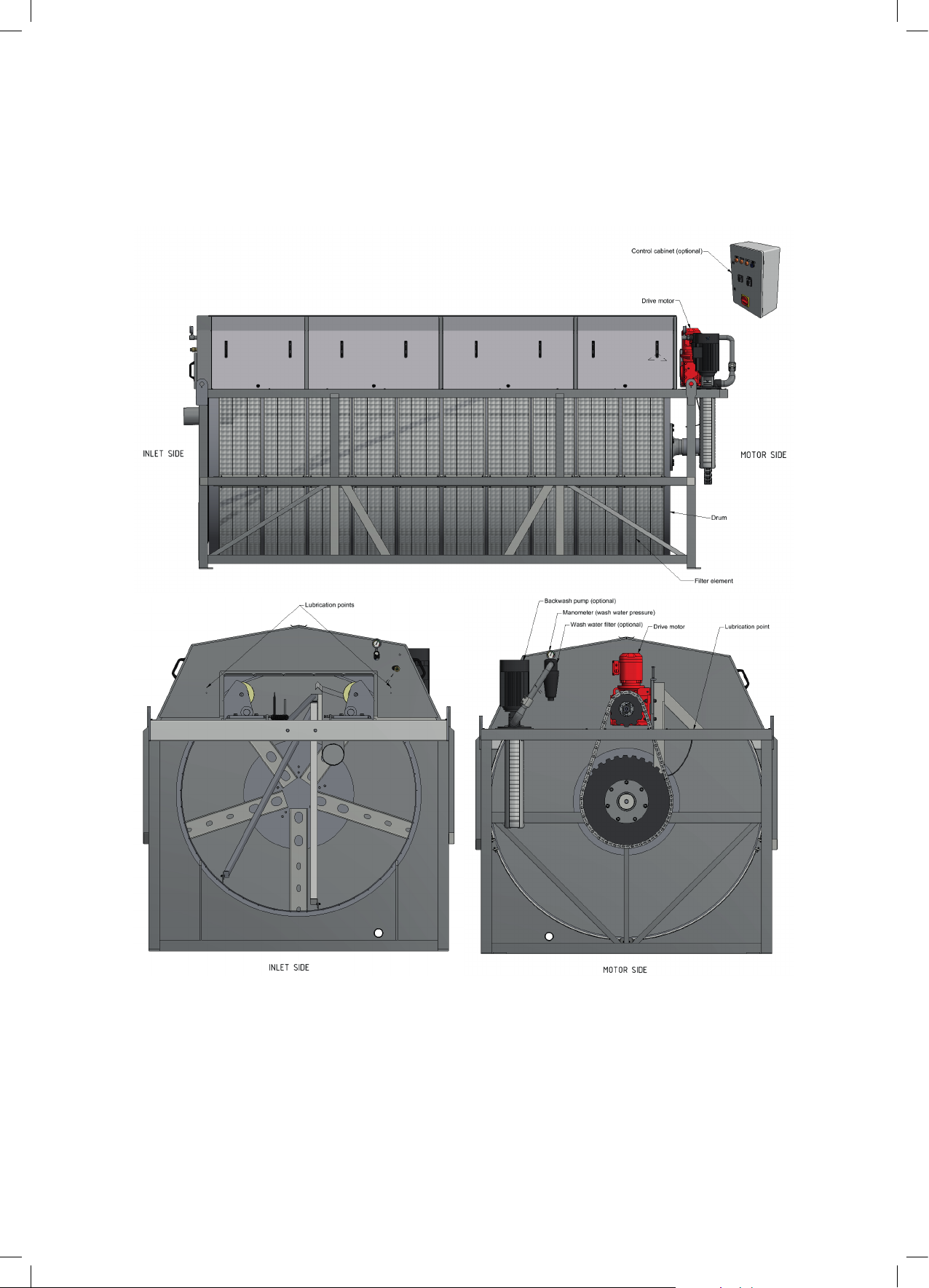
3. HYDROTECH DRUM FILTER 12, 16, & 20 -SERIES
3.1 Overview
Figure 3.1 HDF12/16/20/24 series components, filter with stand
9
10
Operation & maintenance manual, Drum filter HDF 12/16/20/24 -series
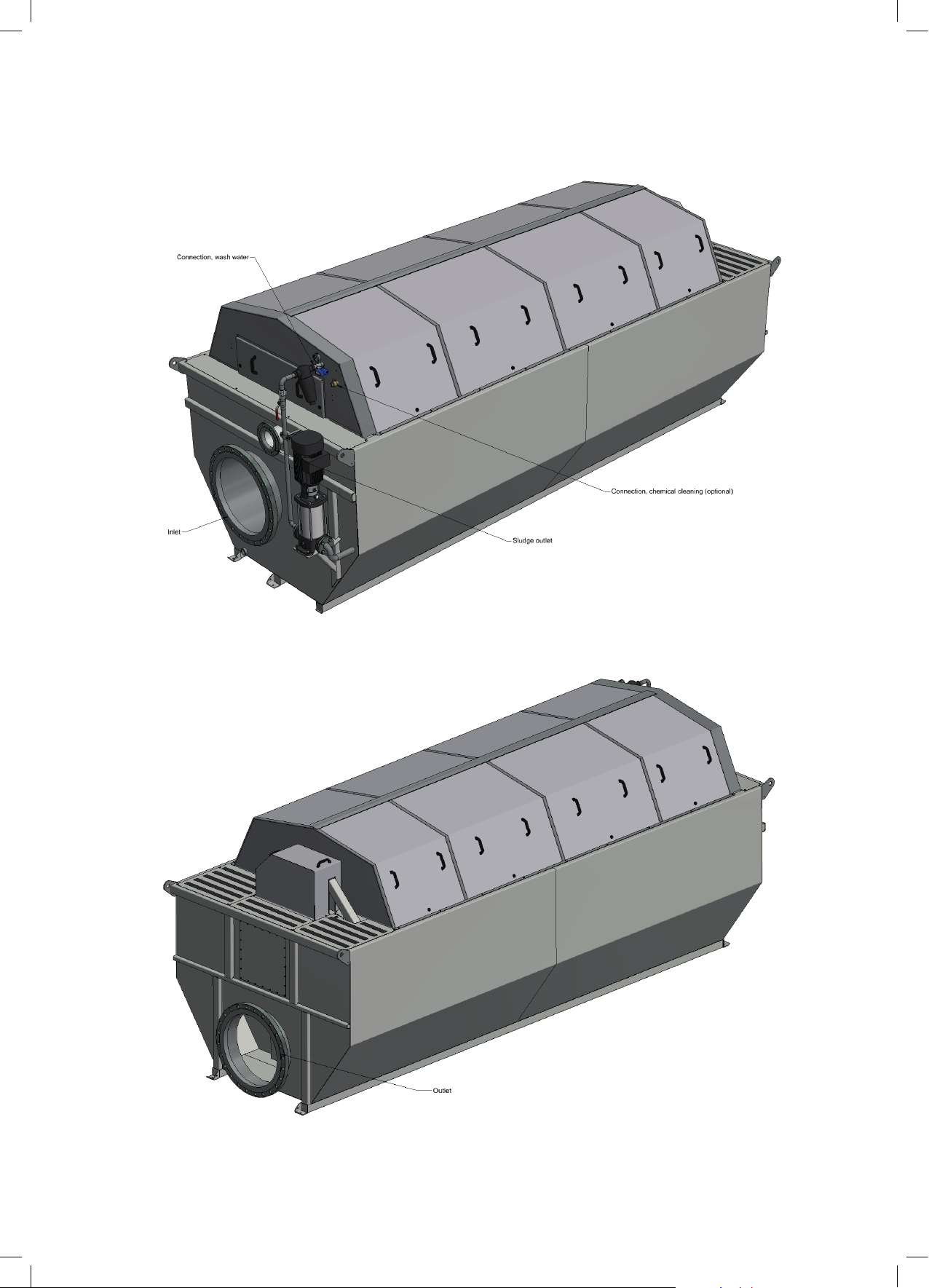
Figure 3.2 HDF12/16/20/24, filter with tank
Operation & maintenance manual, Drum filter HDF 12/16/20/24 -series
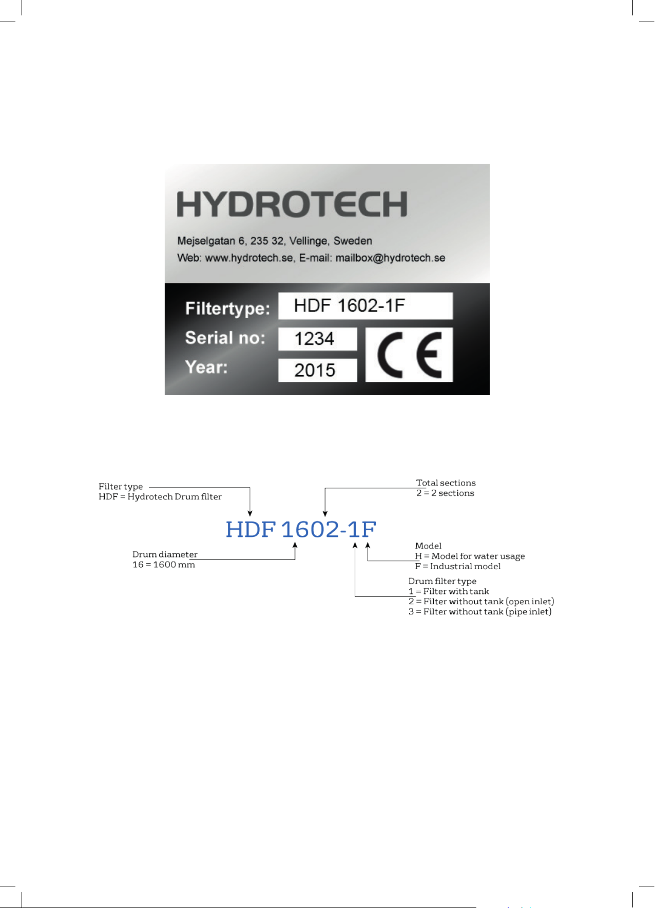
3.2 Identifying the filter
The filter type, serial number and year of manufacture are stated on the identification plate. The
filter type and serial number are also stated on the front of this manual.
Figure 3.3 Filter identification plate
Figure 3.4 Defitition of filter type
11
Operation & maintenance manual, Drum filter HDF 12/16/20/24 -series
4. RECEPTION AND HANDLING
4.1 Reception
Once the equipment has been delivered and received it must be thoroughly checked for transport damage. Document any transport damage before further handling of the equipment. The
consignment note, manual and spare part kit are attached to the equipment. Check all parts
against the consignment note. Some parts may be delivered unassembled. Handle fragile parts
with care. Before lifting the equipment, see section 4.3.
4.2 Storage
Some precautions must be taken to prevent damage to equipment if a long storage time is necessary (several weeks or more):
⊲ The equipment should preferably be stored indoors, in a frost-free area.
⊲ The filter must be protected against direct sunlight if stored outdoors. Heat and UV radiation
can damage the filter elements.
⊲ If the filters are delivered in plastic-covered wooden crates, a special type of corrosion may
occur if stored outdoors, especially in coastal areas. The moisture inside the plastic acts as an
anode and the exposed dry components as a cathode. In these areas, the filters must therefore
be unpacked immediately upon delivery.
4.3 Liing the equipment
⊲ A forklift truck with long forks should
be used when lifting filters in wooden
crates.
⊲ An unpacked filter with tank (type 1)
can be lifted with a fork lift truck, standard crane or with an overhead crane
with lifting straps.
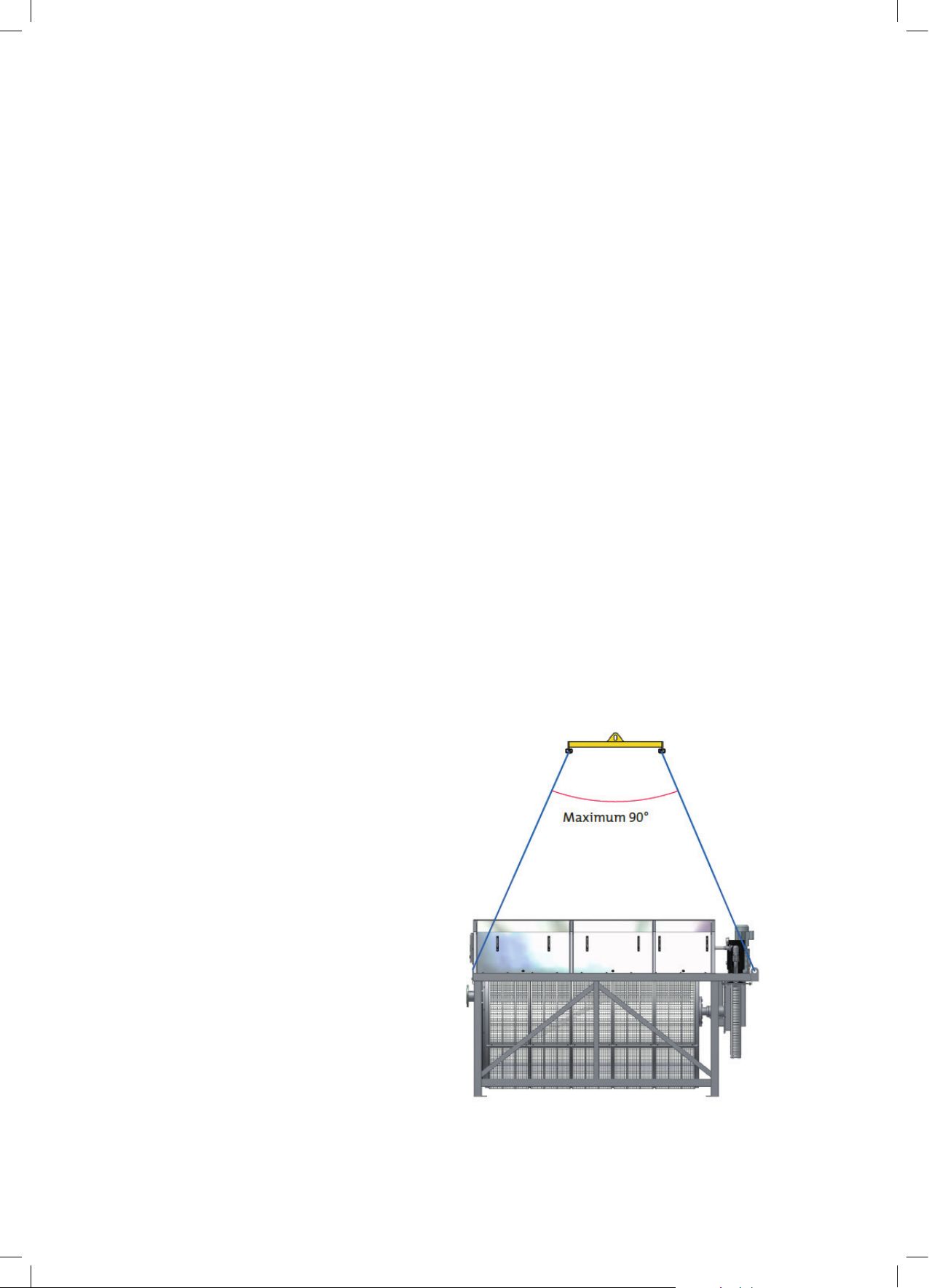
⊲ An unpacked filter without tank (types
2 & 3) can be lifted with a standard crane
or overhead crane and lifting straps. The
straps are positioned as set out in
12
The work area must be cordoned off before unloading in accordance with local regulations to prevent unauthorised access.
Figure 4.1 Lifting points for filter without tank (type 2/3)
 Loading...