

Page 1

- 1 Veo Europe_VIPN-2xxx Observer Plus_UserManual rev1.0 EN
Table of Contents
1. System Features
1-1.Package Contents
1-2.System Requirements
1-3.Hardware Description and Features
1-4.Observer Plus Hardware Specification
2. Installation
2-1. Observer Plus Hardware Setup
2-2. Observer Plus Hardware Setup (Wireless LAN Setup)
2-3. Connecting to an Access Point (AP)
3. Accessing the Observer Plus
3-1.Change the Observer Plus IP Status
3-2.On the LAN with DHCP Server
3-3.On the LAN without DHCP Server
3-4.On the LAN use with the ADSL Router
3-5.Access the Observer Plus by ordinary user login.
4. Observer Plus Network Camera on-line
5. Change Password
6. Camera Control
6-1. Quality Setting
6-2. Resolution Setting
6-3. Frequency Setting
6-4. Camera Advanced adjust
6-5. Operation Mode
7. View Log File
8. Configuration
8-1.System Setup
8-1-1. Camera Name
8-1-2. Camera’s Time
8-1-3. Webserver Port Number
8-2. User Setup
8-2-1. User Management
Page 2

- 2 Veo Europe_VIPN-2xxx Observer Plus_UserManual rev1.0 EN
8-3. Motion Detect Setup
8-3-1. Motion Detection Enable / Disable
8-3-2. Motion detected mail function
8-3-3. Motion detected mail
8-3-4. Motion detected message on the main window.
8-3-5. FTP uploads when motion detected.
8-4.Alert IN Setup
8-4-1.Alert IN Setup
8-4-2.Alert IN with motion detected mail function(mail setting)
8-4-3.Motion detected mail (Alert IN Enabled)
8-4-4.Motion detected messenger on main window(Alert IN Enabled)
8-4-5.FTP uploads when motion detected(alert IN Enabled)
8-5. Network Setup
8-5-1. Manual Setup
8-5-2. Connect to ADSL by PPPOE mode
8-6. Audio Setup
8-6-1. Audio Configure
8-7. DDNS Setup
8-7-1. DDNS Server
9. Snapshots
10. Image Recording
10-1. Save as JPEG
10-2. Save as AVI
10-3. Save Current Picture As…
11.GPIO Function
12.Hardware Reset Function
13. Accessing Observer Plus over the Internet
14.POE(Power over Ethernet) Function
Page 3

- 3 Veo Europe_VIPN-2xxx Observer Plus_UserManual rev1.0 EN
15.Pan and Tilt Control
15-1.Control the camera in the main window
15-2.Position Points Pre setting
15-3.Image Rotate Setting
15-4.Camera Moving Step Size
Page 4

- 4 Veo Europe_VIPN-2xxx Observer Plus_UserManual rev1.0 EN
1-1. Package Contents
Observer Plus Pan/Tilt Network Camera x 1
Power Adapter (5V 2A) x 1
Red Color 10/100 Mbps Ethernet LAN Cable (MDI / X, Cross over LAN cable)
Blue Color 10/100 Mbps Ethernet LAN Cable (MDI)
Observer Plus installation CD-ROM x 1
Observer Plus User’s Manual x 1
Warranty Card X 1
Climber with screws X 2
1-2. System Requirements
To view the camera web page
Web Browser – Internet Explorer for Windows 6.0 or higher
PC with Windows 98, Me, 2000, or XP connected to LAN
To run the included software (IPEDIT.exe) applications
PC - Intel Pentium 4 or higher, 256MB RAM, 150 MB Hard Disk Space
Support 800x600 resolution with 32- bit color Display Card
Support Windows 98SE, Me, 2000, or Windows XP , XP –SP2
To access cameras from the Internet
Broadband Internet Connection (DSL,Cable Modem) with min. 128k upload
speed
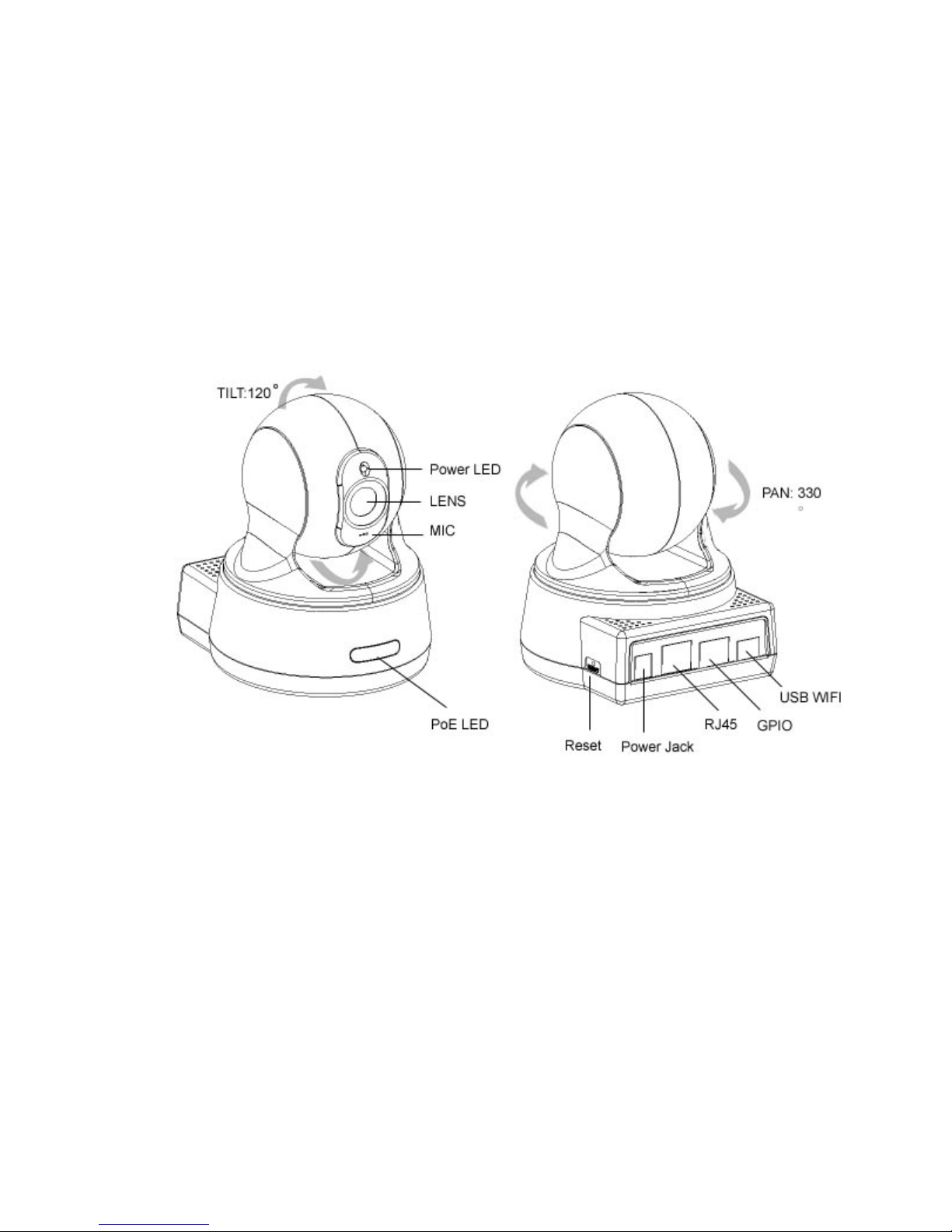
1-3. Hardware Description and Features
Stand-alone network camera for flexible installation.
Simple installation and multiple mounting methods.
Embedded Web Server Supported.
No computer is needed at the monitored site.
Access live video via web browser at anytime and any place for remote
surveillance and management.
2 default HTTP ports supported, they can be changed to fit different network
environments.
Built-in Motion Detection for security at no extra cost.
Standard JPEG Image Format.
Record AVI (Video) or Motion JPEG images onto hard disk for future viewing.
Capture snapshots and video to your PC.
Page 5

- 5 Veo Europe_VIPN-2xxx Observer Plus_UserManual rev1.0 EN
Password protection, Supervisor password system for you to decide who has
authority to access the cameras.
Real-Time Motion Detection for E-mail and FTP alert.
E-Mail the Detected Images to preset e-Mail address.
FTP the Detected Images to preset FTP server.
Directly connect to ADSL by PPPoE, mail the IP setting to preset mail address.
5 different resolutions, 5 different image quality.
3 different Light Frequencies: Outdoor, Indoor 50Hz and Indoor 60Hz.
Unlimited number of users concurrently browsing the same camera.
E-Mail notification for sharing or notifying information actively to the connected
party.
Camera Name Support.
Web console configuration interface.
LAN/WAN interface supported.
Support Fixed IP or Dynamic IP by DHCP.
Log List report.
Built-in Microphone
Network
Fixed IP.
Dynamic IP by DHCP.
Directly connect to ADSL by PPPoE, mail the IP setting to preset mail address.
User Management
User Management for Add User, Delete User, and Change Password.
Administrator, privileged user to change any settings.
General users, view images only.
Camera Control
Resolution: 160x120, 176x144, 320x240, 352x288, 640x480.
Quality: Low, Medium, High
Image Rotate / Flip Function
Video Adjustment: Saturation, Hue, Sharpness
Built-in stepping motor for Camera PAN / TILT
Camera Pan Degree ( Mechanic angle ): 300 degree (-165° ~ +165°)
Camera Tilt Degree ( Mechanic angle ): 120 degree (Down 30° ~ up 90°)
P/T Control: Up ,Down ,Right ,Left, Up-Right ,Up-Left, Down-Right ,Down-Left,
Center
Position presetting : 6 point
Page 6

- 6 Veo Europe_VIPN-2xxx Observer Plus_UserManual rev1.0 EN
Wireless LAN
Support USB Wireless Dongle for IEEE802.11 b and g
Zydas Chipset WiFi USB Dongle
E-Mail the Detected Images to preset e-Mail address.
FTP the Detected Images to preset FTP server.
Motion Detection
Software Real-Time Motion Detection.
Choice of Selected area.
E-Mail the Detected Images to preset e-Mail address.
FTP the Detected Images to preset FTP server.
Browser Support
IE only (ActiveX Control) saves the current image local PC.
ActiveX controls: ActiveX controls support full functions, including the Right
Mouse Button Menu control.
Utility
IPEDIT.EXE to scan the Installed Observer Plus and change the Camera Name
and IP Address
Power
Power DC 5V 2A, switching type power supply
Power Over Ethernet (PoE) , IEEE 802.3af
Power consumption 6.5W (1300mA x 5 V) ,maximum
Page 7
- 7 Veo Europe_VIPN-2xxx Observer Plus_UserManual rev1.0 EN
1-4. Observer Plus Hardware Specification
Built-in web server allows camera to be accessed by standard Internet browser
Network, RJ-45: 10Base-T/100Base-TX Ethernet networks
Network ready, IP address able (no PC required.)
Motion-JPEG based compression
Size: 160 mm x 70 mm x 57 mm
Weight: 500g
Power Supply: 12 V , DC/ 2A
Page 8
- 8 Veo Europe_VIPN-2xxx Observer Plus_UserManual rev1.0 EN
2. Installation
Before installing the Observer Plus, you should have an available Ethernet LAN
connection (RJ-45 port). To view the camera’s image or make any manual
configuration changes, you will need a Windows PC with Internet Explorer 6.0 or
higher and connection to the LAN.
2-1. Observer Plus Hardware Setup (LAN Setup)
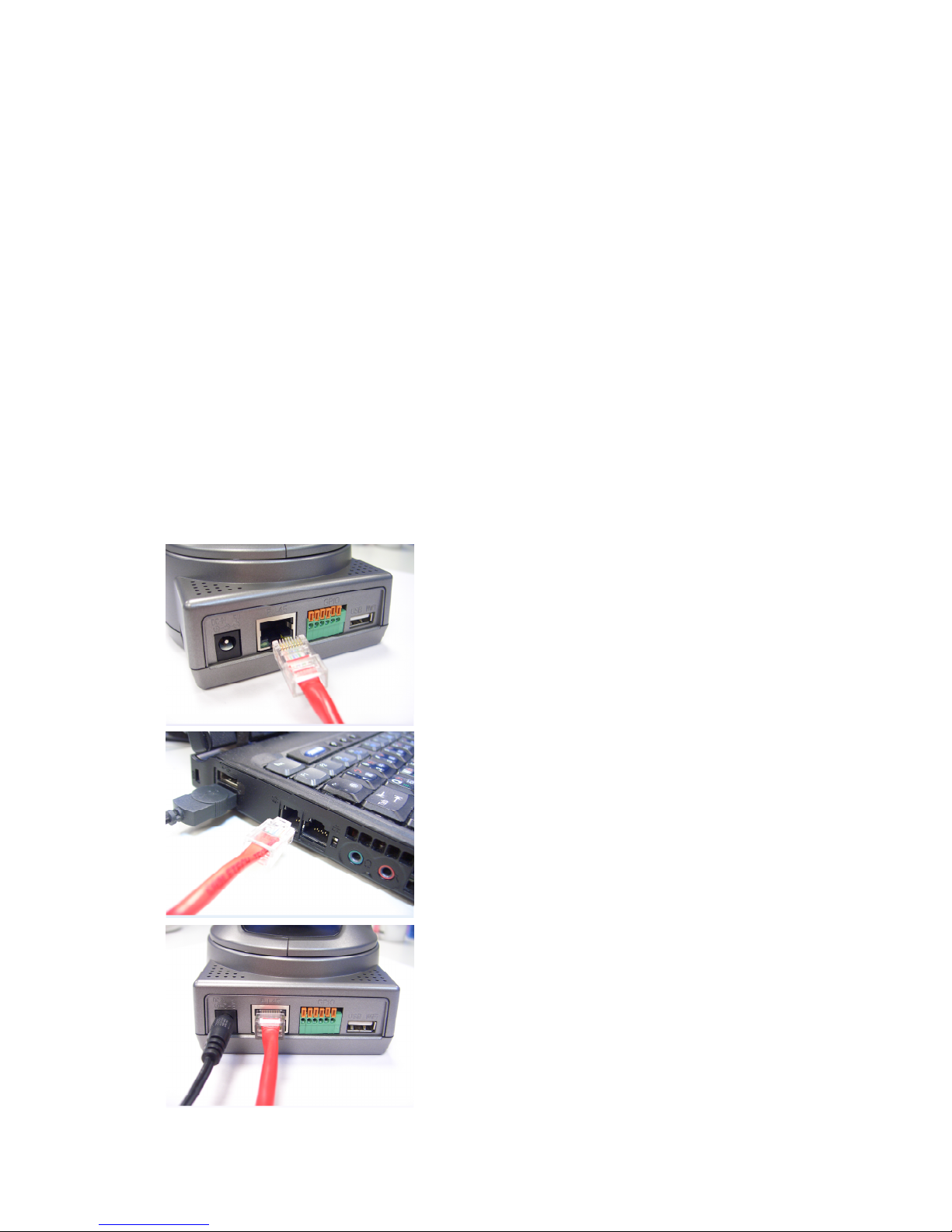
1. Plug the Ethernet cable into Observer Plus
2. Plug the Ethernet cable into PC or Router
3. Connect the Power Supply to the Observer Plus, Camera power LED ON
4. Wait 45 sec to 60 sec, the camera will auto Pan and Tilt, moving to camera
center
5. Use the IPEdit.exe tools to find the Observer Plus and setup camera IP address.
6. Use IE to view the Observer Plus image.
7. Connect to Router using Blue Cable when settings completed
Step 1
.
Plug the Ethernet cable into
Observer
Plus
Plug the included RED Color Ethernet cable into the
RJ- 45 connector at the back of the camera as
shown.
Step 2
.
Plug the Ethernet cable into PC
or Router
1.Temporarily disconnect the existing network cable
from the PC.
2.Plug the other end of the Ethernet cable into any
available LAN port. A typicalhome router /gateway
connection is shown on the left.
Step 3
.
Connect the Power Supply to the
Observer
Plus
Connect the power supply to the back of the Observer
Plus as shown, and then plug the supply into an
available power outlet.
The Camera Power LED ON (Blue)
Page 9
- 9 Veo Europe_VIPN-2xxx Observer Plus_UserManual rev1.0 EN
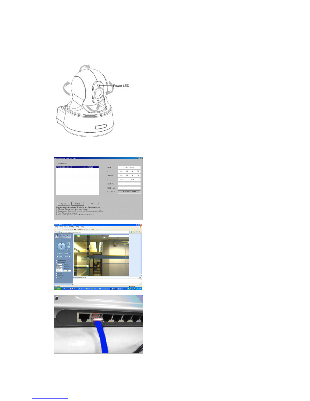
Step
4. Ensure the
Camera
power light is li
ghting
When the Observer Plus is connected with power,
the LED light on top of the Observer Plus will light
up. This indicates that the Observer Plus is powered
on.
Wait 45 sec to 60 sec, camera will auto pan tilt
Step
7. Connect
Camera
to the ADSL Modem
or LAN Hub
1. Remove the Red LAN cable from the PC when all
the settings are completed.
2. Reconnect the existing network cable to the PC.
3. Using the blue network cable provided, connect
one end to the IP-Cam, and the other, to the
ADSL model of LAN hub.
4. Return to Step 6
Step
6. Using IE to
view
Observer Plus
image
1. Start the Internet Explorer, key in the IP Address
of Observer Plus into the Address field, such as
192.168.1.245.
2. Turn the lens to the left or right to adjust the
clarity of the focus.
Step
5.Using IPEdit.exe to test the IP
-
Cam
1. Use IPEDIT.EXE to find the installed Observer Plus.
2. The Observer Plus without IP allocated by DHCPwill
have a default IP Address of 169.254.xx.xx.
3. Select this Observer Plus on Camera List Window.
4. The default configuration will be shown on
the right window.
5. Change Observer Plus network settings.
Update the Camera Name (Fixed IP).
Update the Gateway Address
Update the IP address
Update the Network Mask
Http Port update the 80 port then ‘Submit’ it.
After the ‘Submit’button is clicked, the IP information of
this Observer Plus will be updated.
Page 10
- 10 Veo Europe_VIPN-2xxx Observer Plus_UserManual rev1.0 EN
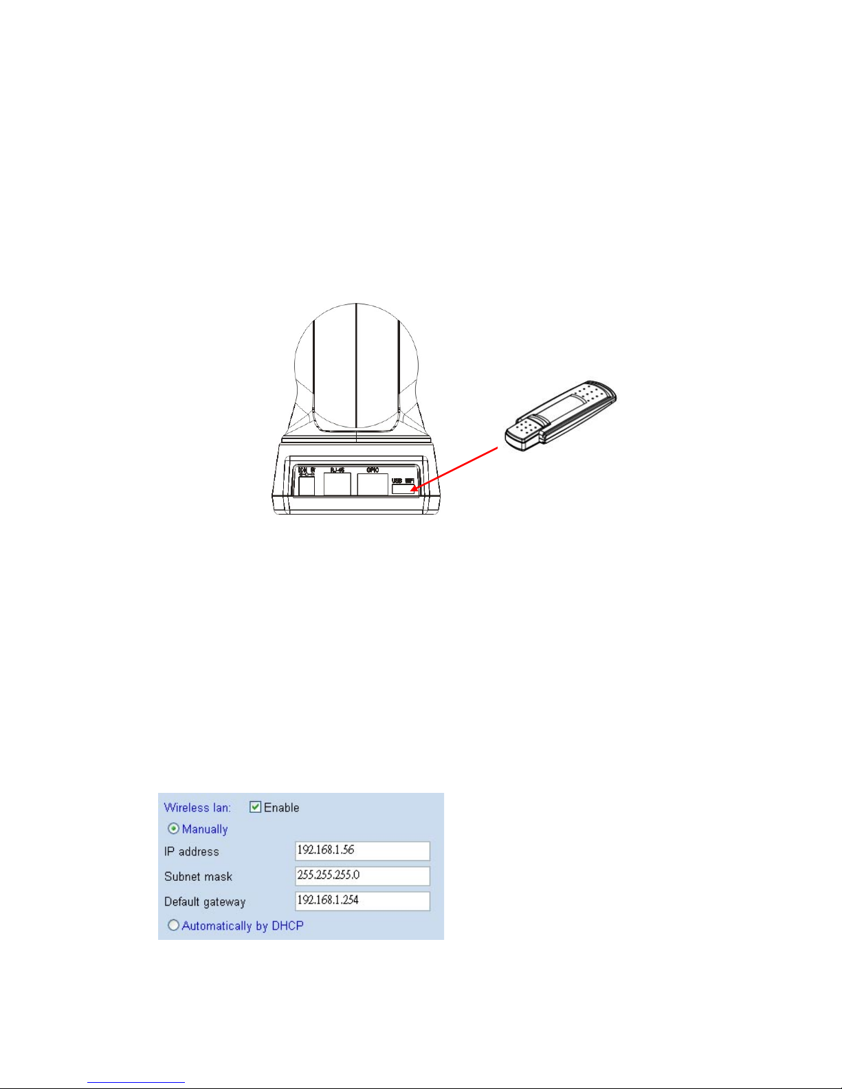
2-2. Observer Plus Hardware Setup (Wireless LAN Setup)*
*Only available for VIPN-2100 WIFI
The Observer Plus provides a USB port for extra device.
Check the diagram for extra function
Observer Plus VIPN-2XXX Network Camera support wireless LAN USB Dongle, the
USB port in camera back panel. The camera support dual mode, LAN and WLAN,
when you want to use wireless LAN with Observer Plus VIPN-2XXX, please follow
setup step and notes.
1. Setup first your camera to the router as explained in the Installation
2. Plug Observer Plus USB WiFi Dongle into camera WiFi USB port
3. Use IE browser, into Camera Configuration page -> Network page
4. Wireless LAN Enable. And Manually setup IP address, Subnet mask, Gateway or
Automatically by DHCP
Page 11
- 11 Veo Europe_VIPN-2xxx Observer Plus_UserManual rev1.0 EN
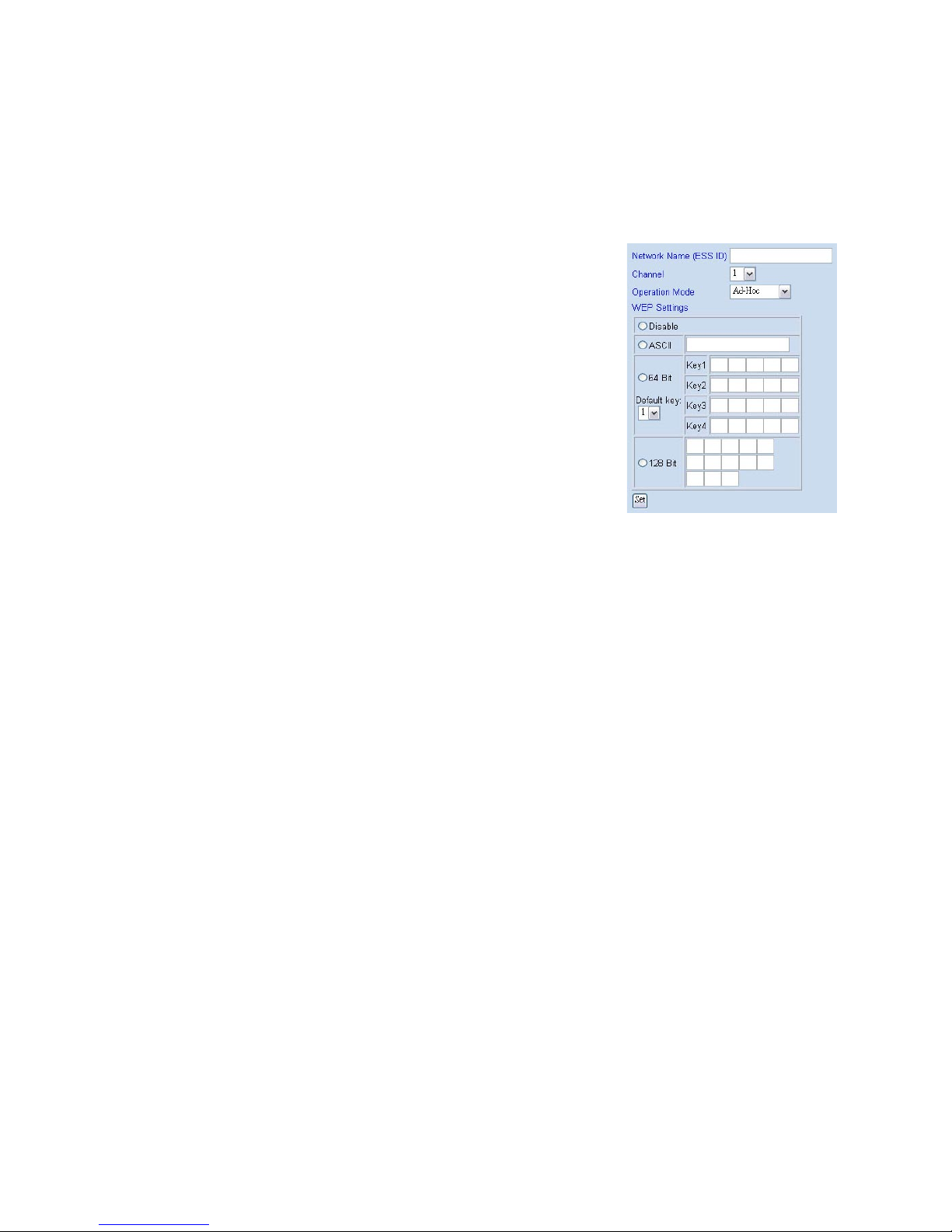
5. Configuration page -> Wireless Interface page
Setup wireless all setting value, such as
Network Name (ESS ID), Channel, Operation
Mode and WEP settings, than click Set button
6. Select “Reboot Immediately” button for reboot.
(wait 60sec)
7. Use IP-EDIT.EXE software to find out camera
(Now, camera in Wireless LAN status)
8. Use IP-EDIT.EXE, Camera List will show 2 cameras.
9. Use IE Browser to watch IP-cam image (wireless mode)
10. If you can find camera in IP-EDIT list and see camera video from IE, than mean
is your camera wireless setup completed, when camera in wireless mode,
IP-Edit software can’t change any setting, you must use IE into setup page to
change camera setting.
11. Configuration page -> Network -> Disable LAN
12. Remove LAN Cable from camera RJ-45 connector and select
“Reboot Immediately” button for reboot again (wait 60 sec)
13. Use IE Browser to watch IP-cam image (wireless mode)
NOTES: If you can’t find camera in IP-EDIT list , than mean is something wrong,
you need use reset button to reboot camera and setup again (from step 1).
Use Pin to press Reset button 10 sec, than camera will reboot
Page 12

- 12 Veo Europe_VIPN-2xxx Observer Plus_UserManual rev1.0 EN
2-3. Connecting to an Access Point (AP)
Your 802.11g USB 2.0 USB dongle also enables a group of wireless stations to
communicate with each other. It acts as bridging functions between the wireless
network and the wired LAN network.
e.g. ASCII : [0~9] [A~Z] [_] , 64bit/5 characters,128bit/13 characters
Page 13

- 13 Veo Europe_VIPN-2xxx Observer Plus_UserManual rev1.0 EN
3. Accessing the Observer Plus
3-1. Change the Observer Plus IP Status
Using the IPEdit.exe, you could select the
different network options.
The PC network options will display the
Gateway and Net mask network settings,
Which you can edit with IPEdit.exe .
Alternatively, you may contact your network
system administrator to provide you with the
details of your network Gateway and Net mask
settings.
Enter the Camera’s IP number.
If you allow outsiders to see the Observer Plus, please enter another IP
address.
If you only want the Observer Plus to be viewed in the internal network, you
could enter a local IP number Example: 192.168.1.88.
Clicking “Submit” will update all of changes mode to the Observer Plus settings.
Launch IE Browser.
Go to Observer Plus Network Setup PPPoE Set ADSL User ID and Password
provided by Hinet Click Submit and restart the PC.
Page 14

- 14 Veo Europe_VIPN-2xxx Observer Plus_UserManual rev1.0 EN
3-2. On the LAN with DHCP Server
3-3. On the LAN without DHCP Server
1. Use IPEDIT.exe to find the installed
Observer Plus.
2. The Observer Plus without IP allocated
by DHCP will have a default IP Address
of 169.254.xx.xx.
3. Select this Observer Plus in the Camera
Lists Window.
4. The default configurations will be shown in
the right window.
1. Update the Camera Name (Fixed IP)
2. Update the Gateway Address (192.168.1.254).
3. Update the IP address of this IP-Cam (192.168.1.xx).
4. Update the Network Mask (255.255.255.0).
5. Http Port1 type in 80 and press ‘Submit’ it.
After the button ‘Submit’ is clicked, the IP information of this Observer Plus will be
updated.
Access this Observer Plus by this IP address; on the Configuration -> Network, the
Fixed IP address was assigned.
1.
Use IPEDIT.EXE to find th
e installed
Observer Plus.
2. Select this Observer Plus in the Camera
Lists Window.
3. The default configurations will be shown
in the right window.
4. Update the Camera’s IP status.
Page 15

- 15 Veo Europe_VIPN-2xxx Observer Plus_UserManual rev1.0 EN
3-4. On the LAN use with the ADSL Router
If the Observer Plus was installed on the ADSL router, the Observer Plus will
dynamically be allocated an IP address from the DHCP server. However, if you want
to access the Observer Plus from the WAN, the Observer Plus IP address needs to
be setup as fixed IP. Same goes for the Virtual Server function of ADSL router, which
needs to be setup as well.
1. Setup the Observer Plus as Fixed IP, such as 192.168.0.49.
2. Enter the administrator page of +ADSL router. (Use sonnet ASDL router as an
example).
3. Enter the Virtual Server Page.
A. Setup the mapping of HTTP Port (80) to 192.168.0.49.
B. Restart the ADSL router.
Then the Observer Plus can be accessed from WAN, by the ADSL WAN IP Address.
3-5. Access the Observer Plus by ordinary user login.
If the user accesses the Observer Plus by an ordinary user account, the Observer
Plus would not allow the user to access the privileged functions. From the following
screen, the Camera Control, Resolution, Quality, and Configuration are disabled.
4. Observer Plus Network Camera on-line
After setting up the IP based on the above step, execute IE directly on PC. The left
side of the above diagram is the control panel and the right side is image display.
Page 16

- 16 Veo Europe_VIPN-2xxx Observer Plus_UserManual rev1.0 EN
5. Change Password
Before you select “Change Password” check button, make sure “User authorization
required” enable the user check function
1. When you want to Change Password, set a new
password to replace the old password.
2. If you get this message from windows screen, that
mean “User authorization required” mode is not
set yet. Please
Click “Configuration User Setup User
Management User authorization required
3. Select “Yes“ then press “Set” button , check box will
enable the user check when the users want to
access the Observer Plus. The login window will
prompt for the User name and Password.
6. Camera Control
On the IE Browser, right mouse click on the video to activate a pop-up menu. You
can then change the camera settings accordingly.
6-1. Quality Setting
The Observer Plus provides 3 image quality settings. The
user can select the Quality setting from the Quality list box.
Low
Medium
High
Note: The value in the list box displays the current setting of the current image.
When you make a new selection, the value on the list box will be changed to the
new image quality settings.
Page 17

- 17 Veo Europe_VIPN-2xxx Observer Plus_UserManual rev1.0 EN
6-2. Resolution Setting
Observer Plus provides 5 resolutions
640 X 480
320 X 240
352 X 288
176 X 144
160 X 120
User can select the desired new setting from the “Resolution” list box.
Note: The value in the list box displays the current setting of the current image.
When you make a new selection, the value on the list box will be changed to the
new image quality settings.
6-3. Frequency Setting
Observer Plus provides the Frequency setting for
Outdoor
Indoor & 50 (For PAL system)
Indoor & 60 (For NTSC system)
6-4. Camera Advanced Adjust
Observer Plus provides the advanced setting for
Saturation
Hue
Sharpness
To control the camera, use the “+” to increase, “-“ to decrease it, or “STD” to
return to default value.
6-5.Operation Mode
Continuous Mode:
The Observer Plus will always try to capture the image
as fast as possible. This is the default setting.
Periodic Mode:
MS (mill-second) or s (second) can be set. The value set must be greater than 0.
Setting the periodic mode to 5 seconds will update the image every 5 seconds. The
time interval can be checked by the time displayed on the image.
Page 18

- 18 Veo Europe_VIPN-2xxx Observer Plus_UserManual rev1.0 EN
7. View Log File
The user can check the log information of the Observer Plus, including the Main Info,
Appended Info, Operator IP, Operator MAC, and Time.
Select the ”Camera Window” button to return to Camera mode.
Page 19

- 19 Veo Europe_VIPN-2xxx Observer Plus_UserManual rev1.0 EN
8. Configuration
Only the administrator can select the “Configuration”;
the ordinary user account does not have this privilege
to access this function.
The screen is the main menu for configuration setting, when the administrator
selects the “Configuration” in the main window.
Observer Plus provides 6 types of configurations:
System Setup
User Setup
To add/delete user, change password;
Enable/Disable user check.
Add / Delete User Account.
Change Password.
Motion Detection
Enable/Disable motion detection.
Motion detected mail setting.
Motion detected FTP setting.
Alert OUT setting
Alert IN Setup
Alert IN Setting
Motion detected mail setting.
Motion detected FTP setting.
Network – Observer Plus Network connection setting.
DHCP – setting the IP dynamically.
Fixed IP – setting the IP manually.
Connect to ADSL by PPPoE.
Wireless Interface
Network Name (ESS ID), Channel, Operation Mode and WEP settings
Page 20

- 20 Veo Europe_VIPN-2xxx Observer Plus_UserManual rev1.0 EN
Audio
Client Configure Setting
Server Configure Setting
DDNS
DynDns
Pan/Tilt
Preset Point – Set /Move/Clear
Rotate 0 / Rotate 180 / Flip Horizontal/Flip Vertical
Step Size – Small/Medium/Large
Camera Window
Turn Back to Live Video Window
8-1. System Setup
8-1-1. Camera Name
The camera name can be set on the “Camera Name” field,
and select “change “ to summit it .
8-1-2. Camera’s time
Select “ NTP ” button
Key in the Sever IP address like: http://www.org.ntp.org
Press ”adjust” to activate
After Observer Plus get the time from NTP server,
it will update the Camera’s time field.
Select “Input new time” button and click on
“Synchronize with PC’s time“
Key in “mm/dd/yyyy” format into “Date“ field,
and “ hh:mm:ss ” by 24 hours format into
“Time“ field!
Select the “Adjust” button to adjust the time!
Page 21

- 21 Veo Europe_VIPN-2xxx Observer Plus_UserManual rev1.0 EN
8-1-3. Web Server Port Number
The implementation supports 2 HTTP port settings. The HTTP “Port 1” is set to 80;
the HTTP “Port 2” is set to 8080. The user can access the Observer Plus by
http://xx.xx.xx.xx/
or
http://xx.xx.xx.xx:8080/
to access the Observer Plus.
It is recommended to keep the HTTP “Port 1” as 80 to make sure the Observer Plus
can be accessed by the default HTTP port setting access on the LAN.
http://xx.xx.xx.xx/
If multiple Observer Plus are installed on the LAN, also required to be accessed from
the WAN, the HTTP “Port 2” can be changed as the virtual server port mapping to
support multiple Observer Plus. The following table lists example configurations.
Example:
IP-Cam IP HTTP
port.1
HTTP
port.2
Virtual
Server Port
Setting
Access IP-Cam on LAN Access IP-Cam on WAN
IP: 68.68.68.68
192.168.1.1 80 8080
8080
192.168.1.1
http://192.168.1.1
http://192.168.1.1:8080
http://68.68.68.68:8080
192.168.1.2 80 8081
8080
192.168.1.1
http://192.168.1.2
http://192.168.1.1:8081
http://68.68.68.68:8081
192.168.1.3 80 8082
8080
192.168.1.1
http://192.168.1.3
http://192.168.1.1:8082
http://68.68.68.68:8082
8-2. User Setup
8-2-1. User Management
User authorization required:
Checking the Enable use check function will
enable the user check when the users want to access
the Observer Plus. The Login window will prompt for the User name and Password.
Page 22

- 22 Veo Europe_VIPN-2xxx Observer Plus_UserManual rev1.0 EN
If the check box is not checked, then the user check will not be enabled. All users
can access the Observer Plus directly, with the administrator’s permission. A Login
window is not required.
Note: Before you select Enable user check ”Yes” button, please remember to
change the administrator password.
Add a user or change password:
Enter a new user name and password information to
create a new user account, or enter an existing user
account, then set a new password to replace the old
password.
Confirm by clicking on the [Set/Change] button to
create the account or change password.
After submitting, the “Current User List:” would display the newly created user
account. In this example: “newuser”.
8-2-2. Delete User
Select the user account from the “Username” list box.
Click the [Delete] button to delete the selected user account. A confirmation
window will prompt the user to select “OK” or “Cancel”.
After selecting the “OK” button, the selected user account will be deleted from the
“Current User List”. In this example, the “newusername” account will be removed.
8-3. Motion Detect Setup
8-3-1. Motion Detect Enable / Disable
Check the “Enable motion detection” check box to
activate the motion detection.
If the check box is not checked, the motion detection send mail function will not be
enabled.
Enter the “ Sensitivity “ button for select “High” or “Middle “ and “Low “ mode .
8-3-2. Motion detected mail function (Mail Setting)
Page 23

- 23 Veo Europe_VIPN-2xxx Observer Plus_UserManual rev1.0 EN
When motion detection is enabled, the user can setup the mail function to send the
motion-detected images to the preset mail address. The procedures are as follow:
Motion Detect set to “Enable” state.
Setup the “SMTP Mail Server” and E-Mail address.
(Password use or not)
Enter the sender’s email address in “Sender” field
and the recipient’s email address in the “Receiver”
field.
The user can change the “Subject” field.
If the mail server needs authentication, check the
“Password” check box. Also, enter the password;
otherwise the “Password” field does not need to
be filled in.
Check the “Send mail when motion detected” check box to enable the operation.
If the check box is not checked, the motion detected send mail function will not
be enabled.
Confirm by selecting [Save Settings] option to save the settings.
Note:
If all of the items are enabled resulting in a motion event detection, the Observer
Plus will send the motion-detected images to the preset email address. The
maximum number of images allowed is 6 images per mail.
8-3-3. Motion detected mail
The received mail will be displayed in a motion picture
form.
Page 24

- 24 Veo Europe_VIPN-2xxx Observer Plus_UserManual rev1.0 EN
8-3-4. Motion detected message on the main window.
When the motion detection function is enabled, and a motion detected, a message
will be displayed at the bottom.
8-3-5. FTP uploads when motion detected.
The motion-detected images can also be uploaded to FTP server. The procedures
are as follow:
Enter the IP address or domain name of the “FTP Server”.
Enter the “Username” and “Password” of the FTP server.
Certain FTP servers need an “Account” field. Leave it blank if it is not needed.
Enter the “Remote folder” upload path information for saving the images.
Confirm by selecting the [Save Settings] option to save the settings.
8-3-6.Alert OUT Setup
When the Alert OUT function is enabled ,
and a motion detected, a message will be
send to Mail or Ftp site by manual setting
Note. About GPIO function, we only provides aset to be possible to use
Please check the image what GPIO IN/OUT may use.
GPIO IN
GND VCC
GPIO OUT
Enable
Page 25

- 25 Veo Europe_VIPN-2xxx Observer Plus_UserManual rev1.0 EN
8-4.Alert IN Setup
8-4-1.Alert IN Setting
When Alert IN function is enabled, the user
can setup the mail function to send the
motion-detected images to the preset mail
address when extra device triggered.
The procedures are as follow:
Motion Detect set to “Enable” state.
Requires External Motion Detector.
8-4-2. Alert IN with Motion detected mail function (Mail Setting)
When motion detection and Alert IN is enabled, the user can setup the mail function
to send the motion-detected images to the preset mail address. The procedures are
as follow:
Motion Detect set to “Enable” state.
Setup the “SMTP Mail Server” and E-Mail address.
(Password use or not)
Enter the sender’s email address in “Sender” field
and the recipient’s email address in the “Receiver”
field.
The user can change the “Subject” field.
If the mail server needs authentication, check the
“Password” check box. Also, enter the password; otherwise the “Password” field
does not need to be filled in.
Check the “Send mail when motion detected” check box to enable the operation.
If the check box is not checked, the motion detected send mail function will not
be enabled.
Confirm by selecting [Save Settings] option to save the settings.
Page 26

- 26 Veo Europe_VIPN-2xxx Observer Plus_UserManual rev1.0 EN
Note:
If all of the items are enabled resulting in a motion event detection, the Observer
Plus will send the motion-detected images to the preset email address. The
maximum number of images allowed is 6 images per mail.
8-4-5. Motion detected mail (Alert IN Enabled)
The received mail will be displayed in a motion
Picture form.
8-4-6. Motion detected message on main window (Alert IN Enabled)
When the motion detection and Alert IN function both enabled, and a motion
detected, a message will be displayed at the bottom.
Motion detection disabled or Motion detection enabled
8-4-7. FTP uploads when motion detected (Alert IN Enabled)
The motion-detected images can also be uploaded to FTP server. The procedures
are as follow:
Enter the IP address or domain name of the “FTP Server”.
Enter the “Username” and “Password” of the FTP server.
Certain FTP servers need an “Account” field. Leave it blank if it is not needed.
Enter the “Remote folder” upload path information for saving the images.
Confirm by selecting the [Save Settings] option to save the settings.
Page 27

- 27 Veo Europe_VIPN-2xxx Observer Plus_UserManual rev1.0 EN
8-5.Network Setup
8-4-1. Manual Setup (LAN)
For fixed IP address users:
On the network environment, the administrator can assign a unique IP address to
each Observer Plus. The procedures are as follow:
Check the “Manually” button.
Enter the “IP Address”, “Network Mask (Subnet mask)”, “Default gateway”, and
the “DNS1”,“DNS2”, as well as ‘DNS3” in formations.
Select “Reboot immediately” to reboot the Observer Plus to allow these settings
to take effect.
DHCP
The “DHCP” is automatically set as the default network setting of Observer Plus.
When an Observer Plus is connected into the LAN, it will issue the DHCP packets to
request an IP address that is dynamically assigned by the DHCP server. If it is
unable to get a DHCP address on a limited tries, the Observer Plus will assign a
default IP address such as “169.254.xx.xx”.
8-4-2. Connect to ADSL by PPPoE Mode
The Observer Plus can directly connect to the ADSL. However, it should be setup on
the LAN environment to setup the PPPoE information before connecting to the ADSL
modem. Power on the Observer Plus and it will dial in to the ISP connection to the
WAN via the ADSL modem.
The procedures are as follow:
Connect to the LAN by DHCP or Fixed IP
Access the Observer Plus and enter [Configuration] [Network Setup]
PPPoE Configuration
select the “Dial on power Up” check box.
If the ADSL Modem and Observer Plus are connected on a hub and after the
PPPoE Information’s are entered, you can then select the “ Save and Dial Now”
option to do the PPPoE dial.
Enter the “User” and “Password” fields with the account and password provided
by the ISP.
Page 28

- 28 Veo Europe_VIPN-2xxx Observer Plus_UserManual rev1.0 EN
If the “Mail after dialed” check box is checked, the mail will be automatically sent
when connected automatically to the ISP.
If the mail server needs authentication, the “Password” check box needs to be
checked and password information, entered.
Enter the sender’s email address in the “Sender email” field and recipient’s email
address in the “Receiver email” field.
The “Subject” field can be modified.
Confirm by clicking on the “Save” button
to save the settings.
If the Observer Plus and ADSL modem are connected
by a hub, the administrator can select ”Dial Now”
to perform the connect operation. On the contrary,
if the Observer Plus and ADSL modem are connected
directly, then there is a need:
To power off the Observer Plus,
To connect to the ADSL modem,
To power-up the Observer Plus,
For the Observer Plus to start dialing.
Once connected, mail the IP address information to the preset e-mail address.
After 10 times of failed try connections, it aborts the dialing operation and the
administrator can reconnect it to the LAN, access it, to find the cause.
Note:
If the PPPoE option “Mail after dialed” is selected, and when PPPoE dials in to the ISP,
a mail that contains the Dial Up ISP Address / Netmask / Gateway address / DNS
Server address will be mailed to preset the e-Mail address.
Page 29

- 29 Veo Europe_VIPN-2xxx Observer Plus_UserManual rev1.0 EN
8-5. Audio Setup
8-5-1 Audio Configure
For fixed Audio option users:
Client Configure:
In “Audio format ” click “PCM” or “Adpcm”
If the check box is not checked, default setting will be “PCM”!
Check the “Audio On/Off “ button for select “On” or “Off “mode for audio enabled.
Server Configure:
Check the “Server Configure ” check
box to select Audio “on” or “off” !
If the check box is not checked, default setting will be “off”!
8-6. DDNS Setup
8-6-1. DynDns setup
Check the “Enable” button
First, make sure you register to DYNDNS
(http://www.dyndns.org). Create a
Dynamic DNS domain. In the DYNDNS
configuration of your Observer Plus, fill in
the “UserName“, “password“ and
“DomainName“ you created in the
http://www.dyndns.org. Submit to save the settings.
Page 30

- 30 Veo Europe_VIPN-2xxx Observer Plus_UserManual rev1.0 EN
9. Snapshots
9-1.Snapshots
Click “Snapshot” button, a new window will pop-up. Right click to save image.
10. Image Recording
10-1. Save as JPEG
1. Select “Image Recording…”
2. The “Image Recording” pop-up window displays. Check the “Save as JPEG”
check box option.
3. Enter the “Download Number” to save the desired number of images, or
“Download No Limit” to save the images continuously, until the “Stop Image
Recording” is selected.
4. Click on the “Save As” button and a pop-up window displays to select the save
path and file name prefix. Select “Save” to continue.
5. Click on the “Start” button to perform the image download process and save
the JPEG files onto the local PC.
Page 31

- 31 Veo Europe_VIPN-2xxx Observer Plus_UserManual rev1.0 EN
Note:
During the downloading and saving process, a yellow mark will be displayed on
the right-down position to indicate the saving process.
Before the “Download Number” of images is reached, or if you may have
selected “Download No Limit”, click on “Stop Image Recording” to stop the
image recording process.
After the “Stop Image Recording”, list the files on the selected saved directory.
These files are named as
file_name_prefixed_yyyy_mm_dd_hh_mm_ss_ms.jpg
10-2. Save as AVI
Select “Image Recording…”
The “Image Recording” pop-up window displays. Check the “Save as AVI” check
Box option.
Enter the “Time”, “Number” or “Size” on each AVI file, until the “Stop Image
Recording” is selected. “Frame Rate” is the frame rate setting of the recorded
AVI file.
Selecting the “No Limit” button will save the video file until the “Stop Image
Recording” is selected.
You can limit the maximum of Frames (images) per file you are recording. Just fill
the number of Frames you want in the Box next to “Maximum number of Frame for
Each File”. When you reach the limit of frames during recording, a new AVI file
would be created.
Click on the “Save As” button and a pop-up window displays to select the save
Page 32

- 32 Veo Europe_VIPN-2xxx Observer Plus_UserManual rev1.0 EN
path and file name prefix. Select “Save” to continue.
Note:
During the AVI file recording, a red icon displays on right-down position of the
image to indicate the AVI saving process.
After the “Stop Image Recording”, list the files on the selected saved directory.
These files are named as filename_prefix_date_time.avi.
The AVI files can be played by any standard Windows Media Player program,
but they require the DixectX 8.1 or higher version software driver to be
installed.
10-3. Save Current Picture As…
1. Click on the “Save Current Picture As …” option to save
the current image display onto the local PC.
2. Enter the name you wish to save as into the “File name”
field. Click on “Save”.
11. GPIO Function
GPIO(General Purpose Input Output)
1 input and 1 output (Support extra device)
Page 33

- 33 Veo Europe_VIPN-2xxx Observer Plus_UserManual rev1.0 EN
12. Hardware Reset Function
Use Pin to push Reset button hole 10 sec, the
Camera will reset , mean is all setup value back
to the factory default.
When you want to reset camera, the camera must be
powered on.
13. Accessing Observer Plus over the Internet
If your home or business LAN is connected to the Internet through a high speed
(broadband) Internet connection, with at least 128 kbps upload bandwidth, you can
access your camera via the web browser from anywhere on the Internet. To do this
you would need to:
1. Know your WAN (Internet) IP address. This is the IP address that your Internet
Service Provider provides you to access the Internet. It may be static (always
the same) or dynamic (can change from time to time).
2. Make sure the two ports used by the camera (80 & 1600) are forwarded by your
router or gateway to the camera.
3. Make sure your camera default gateway is set to the LAN (local) IP address of
your router/gateway.
Page 34

- 34 Veo Europe_VIPN-2xxx Observer Plus_UserManual rev1.0 EN
How to use
Observer Plus
POE
Function?
1. Connect the PoE adapter
(purchased separately) to the
Camera.
2. Power on the PoE switch
button as display.
14. PoE (Power Over Ethernet) Function*
*Need the PoE Adapter sold separately.
What is Power over Ethernet ?
Power over Ethernet (also referred to as PoE or Power over LAN) is a technology
that integrates power into a standard LAN infrastructure. It enables power to be
provided to the network device, such as an IP phone or a network camera, using the
same cable as that used for network connection.
.
PoE LED , When PoE work, Red LED will
light
Page 35

- 35 Veo Europe_VIPN-2xxx Observer Plus_UserManual rev1.0 EN
16. Pan and Tilt Control
16-1. Control the camera in the monitor window
Click on the monitor image, and the camera
moves so that the clicked portion goes to
the center of the display
16-2. Position points presetting
Click the preset position number button from the preset points than the camera will
move to the preset position that you have stored in memory at Set section.
1. Administrator account login
2. Configuration page
3. Pan/Tilt page
Set button: Position setting
Move button: Camera moving to position
Clean button: Clean position setup
16-3. Image Rotate setting
1. Administrator account login
2. Configuration page
3. Pan/Tilt page
Click the arrow
in
the
direction that you want to
move the camera to.
Back to camera center
Back to camera center,
moving to camera pan tilt
limit than back to center
Position presetting : 6
position
Auto Tilt
scan.
O
ne
time scan than back
to camera center
Auto Pan scan.
O
ne
time scan than back
to camera center
Stop all moving
Preset position scan.
One time scan than
back to camera center
Page 36

- 36 Veo Europe_VIPN-2xxx Observer Plus_UserManual rev1.0 EN
16-4. Camera moving step size
1. Administrator account login
2. Configuration page
3. Pan/Tilt page
Default step size is “Medium”
Veo Europe:
Address:
Western Business Park, Unit 1
Shannon, Co Clare
Ireland
Hotline: +35361702099
Support Email: support@veoeurope.com
 Loading...