

Page 1
Ethernet and 802.11b ( WiFi)
Network Camera
Page 1 of 69
Rev. 04-23-2003
Page 2

Table of Contents
Chapter 1: Welcome to the Veo Observer.....................................................................................4
1.1 Package Contents ...............................................................................................................................5
1.2 Requirements .....................................................................................................................................6
1.3 Hardware Description and Features .....................................................................................................7
Chapter 2: Camera Setup...................................................................................................................9
2.1 Hardware Setup (Observer) .................................................................................................................9
2.2 Hardware Setup (Wireless Observer) ................................................................................................. 11
2.21 Wireless Parameter Setup (Wireless Observer)........................................................................... 11
2.3 Mounting the Camera ........................................................................................................................ 13
Chapter 3: Accessing the Camera................................................................................................. 15
3.1 Usernames and Passwords ............................................................................................................... 15
3.2 Web Browser Access ........................................................................................................................ 16
3.3 Camera Configuration ....................................................................................................................... 19
Chapter 4: PC Software Installation.............................................................................................. 23
Chapter 5: Observer Setup Utility.................................................................................................. 25
5.1 Manually Assigning a Static IP address .............................................................................................. 25
5.2 Open a Camera’s Home Page ........................................................................................................... 26
5.3 Updating the Camera's Firmware....................................................................................................... 27
Chapter 6: Observer Studio PC Application............................................................................... 28
6.1 Camera Manager .............................................................................................................................. 28
6.2 Logging into a Camera ...................................................................................................................... 30
6.3 Camera View Controls ....................................................................................................................... 31
6.4 Using the Gallery .............................................................................................................................. 34
6.5 Movie Maker – Making or Editing a Movie ........................................................................................... 34
6.6 Homepage Designer – Designing a Home Page .................................................................................. 36
6.7 Configuring your E-mail Program to Send Files ................................................................................... 41
Chapter 7: Accessing Cameras Over the Internet..................................................................... 43
7.1 WAN IP Address............................................................................................................................... 43
7.2 Network Address Translation (NAT) ................................................................................................... 43
7.3 Port Forwarding ................................................................................................................................ 44
7.4 Default Gateway ............................................................................................................................... 44
7.5 Accessing Multiple Cameras over the Internet..................................................................................... 45
7.6 Dynamic Domain Name Service (DDNS) ............................................................................................ 45
Appendix A: Restoring Factory Default Settings...................................................................... 47
Appendix B: External Microphone................................................................................................. 48
Appendix C: Network Utilities......................................................................................................... 49
C.1 Determining your IP Address and Network Settings ............................................................................ 49
C.2 Using PING...................................................................................................................................... 49
Appendix D: Router Configuration................................................................................................ 51
Appendix E: Internet Explorer Security Settings....................................................................... 58
Page 2 of 69
Page 3

Appendix F: Motion Sensor Setup................................................................................................. 59
Appendix G: Frequently Asked Questions, Troubleshooting, and Technical Support... 61
Appendix H: Estimating Bandwidth Consumption................................................................... 64
Appendix I: Technical Specifications........................................................................................... 65
Glossary................................................................................................................................................ 66
Warranty................................................................................................................................................ 68
Page 3 of 69
Page 4
Welcome to the Veo Observer
1
Chapter
Thank you for purchasing the Veo Observer. The Observer combines a high quality digital video camera with
network connectivity and a powerful web server to bring clear video to your desktop from anywhere on your local
network or over the Internet. The Wireless Observer removes the need for cables by adding an 802.11b (WiFi)
interface.
The Observer and your home or business network form a powerful audio/vi deo remote monitoring solution. Just
place the Observer anywhere on your network, power it up, and it’s ready to be accessed by any PC on the
network running Internet Explorer 5.0 or higher.
The built -in pan and tilt, live streaming audio, and snapshot/video capture functions can all be controlled directly
from the camera’s on -board homepage. Capability for motion detection with e-mail notification may be added by
purchasing an optional motion detector. The included Veo Observer Studio PC software adds multi-camera
viewing and convenient, single click access.
Use the Observer to keep an eye on your home or business when you can’t be there. Give friends and relatives a
window into your world or monitor and record anything from anywhere on the Internet.
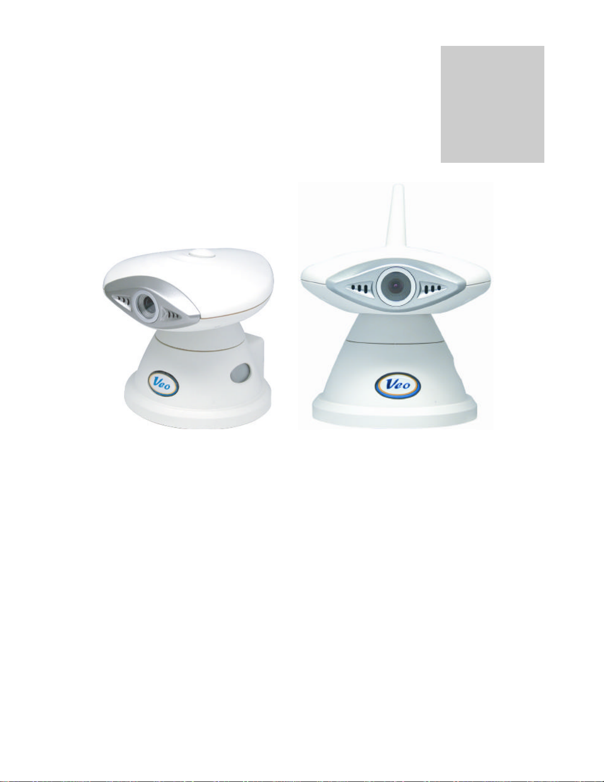
Observer Wireless Observer
Page 4 of 69
Page 5

1.1 Package Contents
Before installing your Observer camera, please check your pac kage contents to ensure that all
items have been included. If any of the listed items are missing, please contact your reseller from
where you purchased the camera for assistance.
Wireless Observer
The package includes:
1 – Veo Wireless Observer camera
1 – Mounting bracket
2 – ¼” Mounting screws and plastic anchors
1 – 10’ Power adapter
1 – 6’ serial cable
1 – Quick Start Guide
1 – Veo Observer camera installation CD -ROM
(located inside the Quick Start Guide)
Observer
The package includes:
1 – Veo Observer camera
1 – Mounting bracket
2 – ¼” Mounting screws and plastic anchors
1 – 10’ Power adapter
1 – 15’ Category 5 10 Mbps Ethernet cable
1 – Quick Start Guide
1 – Veo Observer camera installation CD -ROM
(located inside the Quick Start Guide)
Page 5 of 69
Rev. 04-23-2003
Page 6

1.2 Requirements
To connect the camera to your LAN:
Wireless Observer
(Infrastructure Mode)
802.11b (WiFi) Access point
To view the camera web page
• Web Browser – Internet Explorer for Windows 5.0 or higher
• PC with Windows 98, Me, 2000, or XP connected to LAN
To run the included software applications
• PC – Intel Pentium II or equivalent, 300MHz or above, 64MB RAM, 150 MB Hard Disk Space, 800x600
resolution with 16-bit color
• Windows 98, Me, 2000, or XP
To access cameras from the Internet
• Broadband Internet Connection (DSL, Cable Modem) with min. 128k upload speed
Note: A fixed IP address is not required to access cameras from the Internet. However, if the IP
address provided by your Internet Service Provider is dynamic (changing) then signing up for a
dynamic DNS service will make accessing from the Internet much more convenient. Signing up for a
DDNS is free an d easy. Please refer to Section 7.6: Dynamic Domain Name Service (DDNS) for
more information.
Wireless Observer
(Ad-Hoc Mode)
802.11b (WiFi) network
interface card for PC
Observer
Open RJ-45 port on your
router/gateway
Page 6 of 69
Page 7
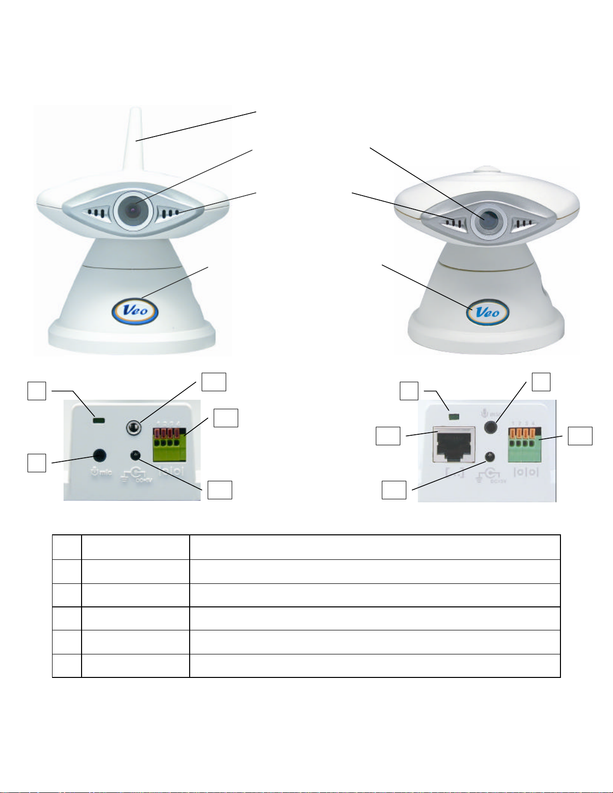
1.3 Hardware Description and Features
Lens
Microphone
Observer
-
Connections
Antenna
Wireless Observer
Observer
Wireless Observer
-
Connections
1 1 2 2 3 3 4 4 5 6
VGA CCD sensor with
fixed focus lens.
Monitor or record
sound using the built-
in microphone.
Power Button
Turn the camera on or off. When
the power button is held down
while the camera is on for 6
seconds the camera settings will
reset to the factory defaults.
The power button light will blink
when video is being streamed.
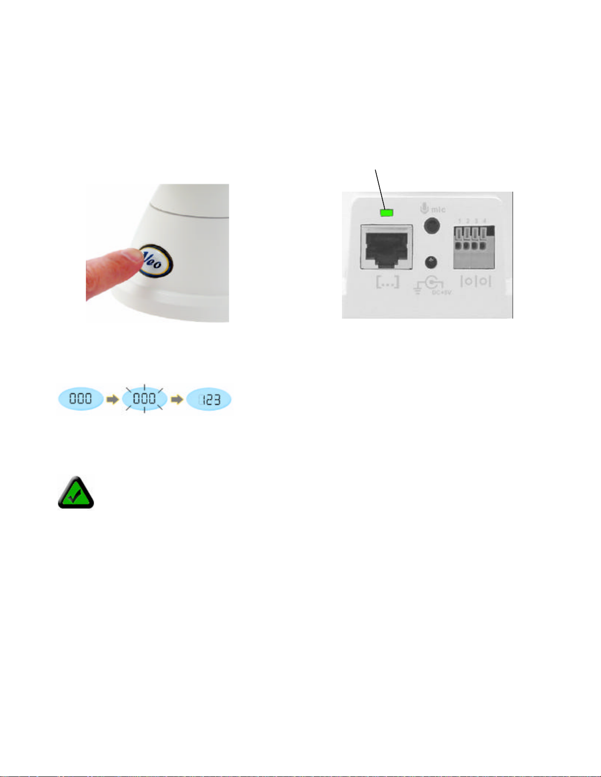
1 Network Activity LED
2
3 Motion Sensor Jack
4
5
6
External Microphone
Connection Port
External Power
Connector
RJ-45 Ethernet Port
(Observer only)
Serial Port
(Wireless Observer)
The green LED indicates if there is a connection to your network. If there is
network activity, the green LED will blink.
Connect a standard 1/ 8” (3.5 mm) computer microphone into this port to
monitor/record audio further away. (External microphone not included)
Connect an external motion sensor to trigger email alerts with images attached.
See the motion detection section for more information. (Optional)
Connect the included power supply. Warning: Use only the included power
supply or you may damage your camera.
Used to connect the Observer to your LAN using the included Ethernet cable.
Used to configure your wireless settings using the included serial cable.
Page 7 of 69
Page 8

IP Address LCD
The LCD will indicate the last three digits of your IP Address. For
xample, if the IP Address “192.168.0.123” is assigned to the
Veo Observer Camera, the LCD will display “123.” Refer to
IP Address Display
e
Section 2.2 Getting an IP address for more information.
Page 8 of 69
Page 9
Camera Setup
2
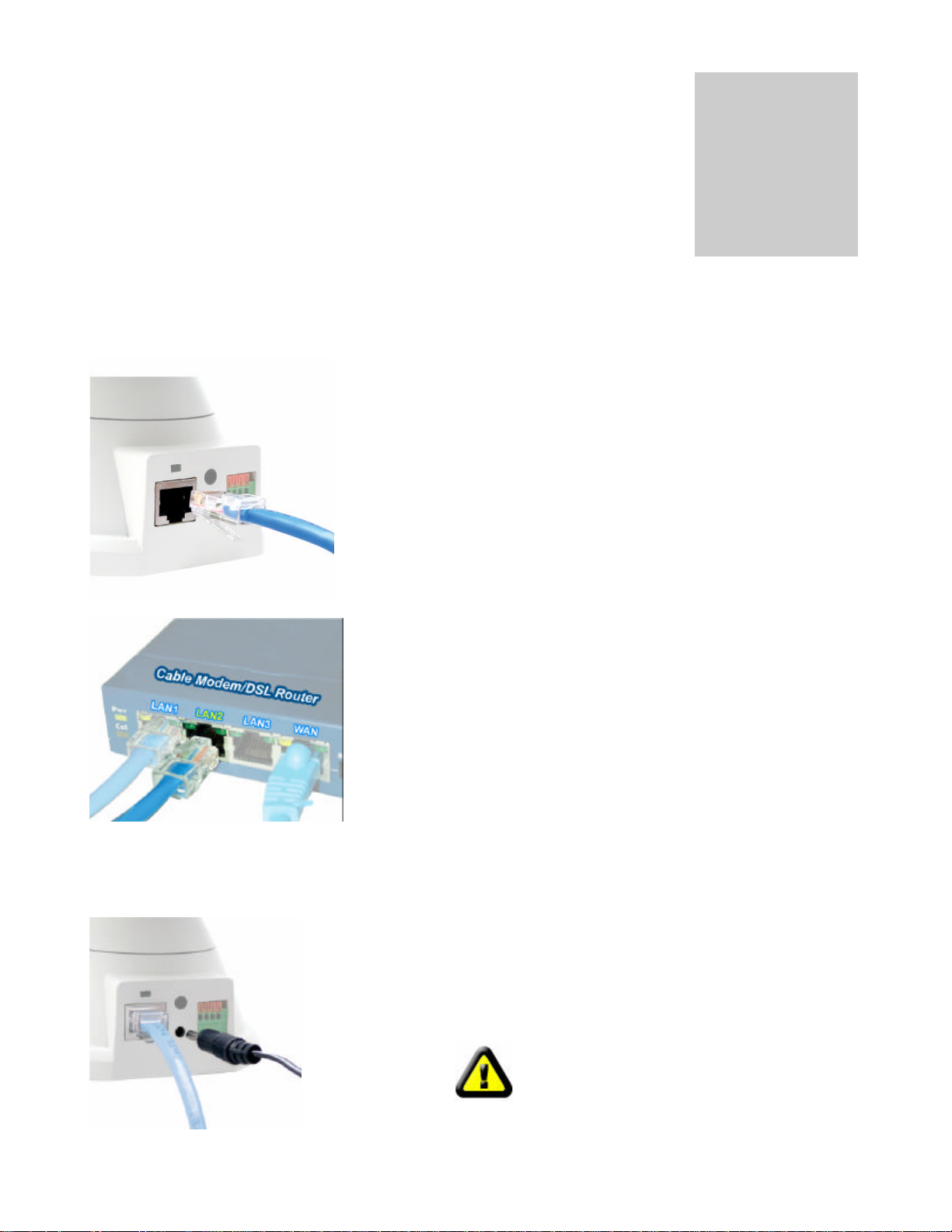
Step 1
. Plug the included Ethernet cable into the RJ
-
Step 2
. Plug the other end of the Ethernet cable into
Step 3
. Connect the power supply to the back of
into an available power outlet.
Observer (Ethernet) Network Camera
Before installing the Veo Observer Camera, you should have an available Ethernet
LAN connection (RJ-45 port). To view the camera’s image or mak e any manual
configuration changes, you will need a Windows PC with Internet Explorer 5.0 or
higher, also connected to the LAN.
2.1 Hardware Setup (Observer)
Connecting the Ethernet cable
45 connector at the back of the camera as shown.
Chapter
Connecting the power adapter
any available LAN port. A typical home
router/gateway connection is shown on the left.
the camera as shown, and then plug the supply
CAUTION: Make sure to only use the power
adapter supplied with your Veo Observer
Network Camera. Using a non-approved power
adapter may damage the camera.
Page 9 of 69
Page 10
Step 5.
Check that the green
Ethernet status LED on the back of
t indicating a good
LAN connection. The LED will blink
Step 4
. Press the power button on
the front of the camera to turn it on.
The button lights up confirming that
Turning the camera on
Step 6. Observe the IP address display on the lowe r left side of the camera.
the camera is powered up.
the camera is li
when there’s activity.
As soon as you power up your camera you’ll notice that the IP address display starts blinking. This means the
camera is searching for an IP address using DHCP. After a few seconds the display stops blinking and shows
the last 3 digits of the address it received.
Note: If the display continues to blink for more than a minute, your network may not support DHCP
and you will need to assign an address manually. Refer to Section 5.1: Manually Assigning a
Static IP Address for mo re information on manually assigning an IP address.
At this point the camera is communicating with your network and is ready to be accessed. You’re almost ready
to access its home page and begin using the camera. There are two ways to point Internet Explorer to the
camera and open its homepage:
1. Install and run the Veo Observer Setup Utility included on the CD-ROM. The Setup Utility will locate
cameras on your network automatically. Refer to Chapter 4 if you need help installing the software and
Chapter 5 for detailed help with the Setup Utility.
2. Open Internet Explorer and type the camera’s IP address into the address bar.
Determining a Camera’s full IP address using the IP display
Other than the last 3 digits, all devices on a LAN share the same IP address. The portion of the address
common to all devices is known as the network address. Most home networks use either 192.168.0 or
192.168.1 for their network address. If you know your network address, you can simply combine it with the 3
digits shown on the camera’s display to determine the complete IP address of the camera. For example, if your
Page 10 of 69
Page 11
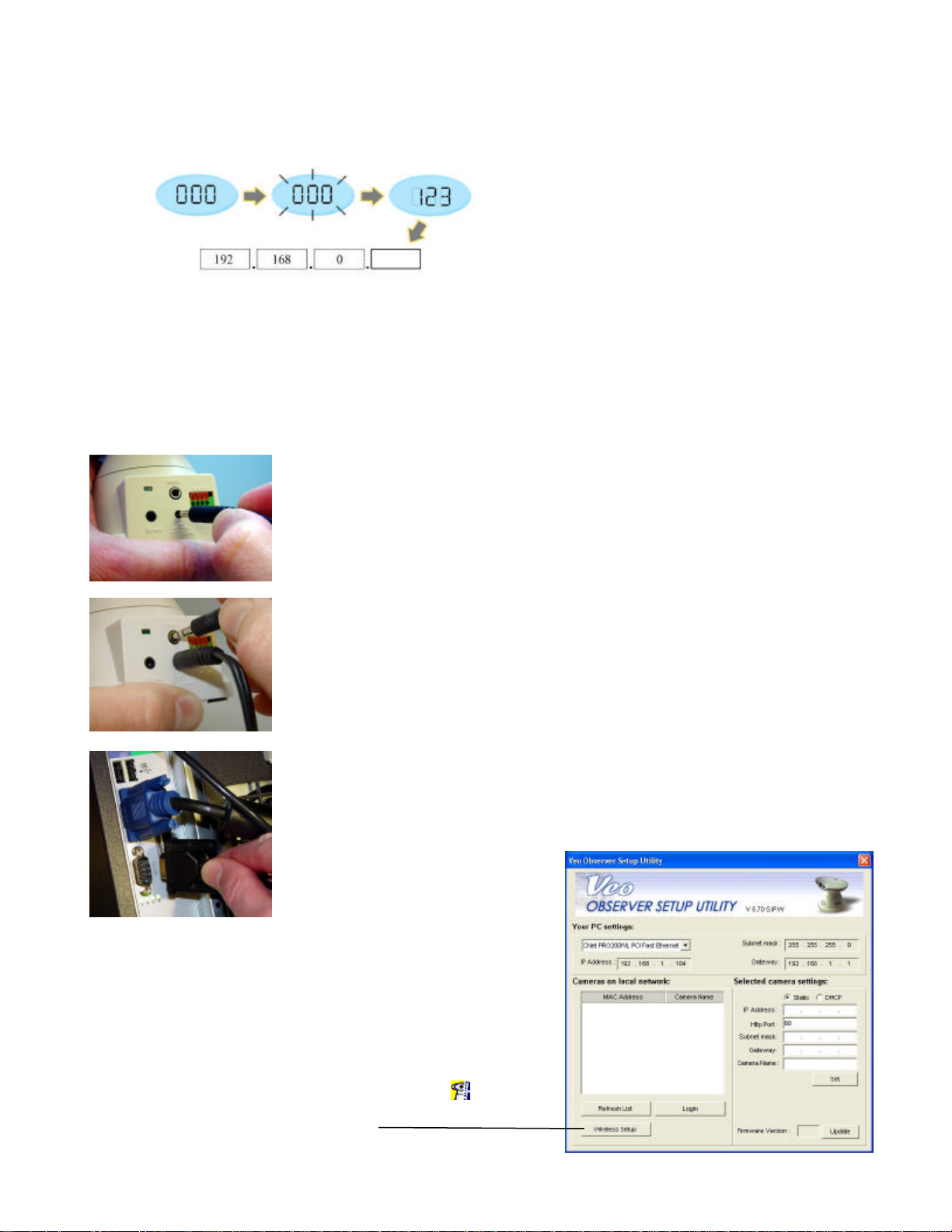
network address is 192.168.0 and the camera display is showing 020, the IP address for the camera is
Step 3
. Plug the other end of the serial
Step 2
. Plug the serial cable into the port
Step 1
. Connect the power supply to the
192.168.0.20 (drop leading zeros). You can easily determine your network address by checking the IP address
of any PC on the network or using the Observer Setup Utility.
Using the IP display to determine your camera’s complete IP Address
2.2 Hardware Setup (Wireless Observer)
Before installing the Wireless Observer camera, you should set up your wireless access point/wireless
broadband router or ad -hoc peer and verify that you can connect to it from a PC. To view the camera’s image or
make any manual configuration changes, you will need a Windows PC with Internet Explorer 5.0 or higher, also
connected to the LAN.
back of the camera as shown, and then
plug the supply into an available power
outlet. The camera will immediately
power on as indicated by the power
status button on the front.
labeled RS232 at the back of the
camera.
cable into an open serial port on your
PC.
2.21 Wireless Parameter Setup
Step 1. Install and run the Observer Setup Utility included on the
CD-ROM.
1. Insert the CD and follow the installation directions. Refer to
Chapter 4: PC Software Installation if you need help
installing the software.
2. Click on the Veo Observer Setup Utility icon to run the
program. The screen shown on the right will appear
Step 2. Click the “Wireless Setup” button.
Page 11 of 69
Page 12
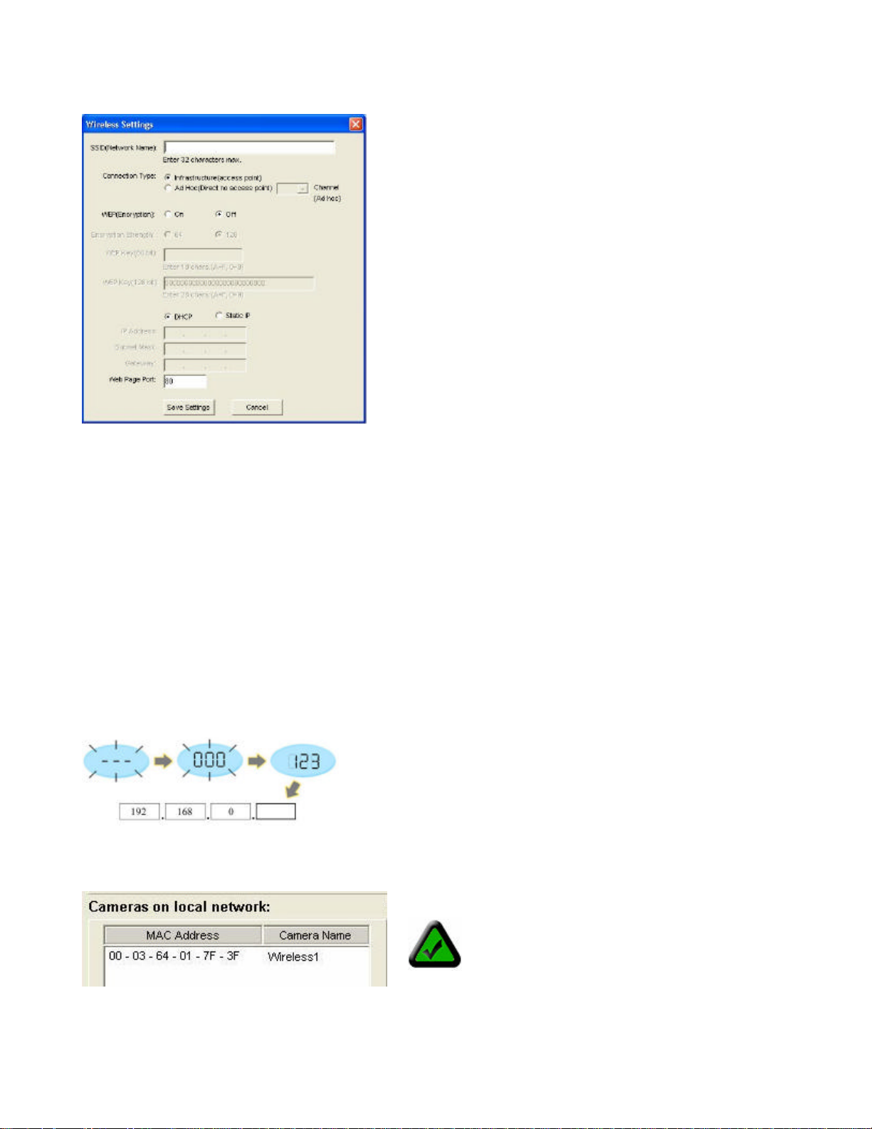
The wireless setup dialog appears showing the camera’s current wireless settings which are the defaults.
SSID (Network Name): Enter the SSID (name) of the access
point to which the camera will connect. Be sure to enter the SSID
exactly as it appears on your access point’s setup page.
Connection Type: Select Infrastructure if the camera will
connect to an access point/wireless broadband router. This is the
typical setting on most home/business networks.
–or—
Select Ad Hoc if you will connect directly from a PC with a
wireless network adapter (NIC). If using Ad Hoc mode, select a
channel to use (no channel selection is required for infrastructure
mode).
WEP (Encryption): If you have enabled WEP encryption on
your network , you must configure your Wireless Observer to use
exactly the same WEP key and key length as your access point
or Ad Hoc peers. Otherwise, leave it turned off.
Network Settings
DHCP: Leave the camera set to DHCP if you want your access point to assign the camera’s network
settings automatically.
Static IP: Select Static IP to set the camera’s IP address, subnet mask, and gateway address manually.
Web Page Port: Leave this set at 80 for now.
Step 3. Click “Save Settings” to save your new settings to the camera. Click “OK” to close the settings window.
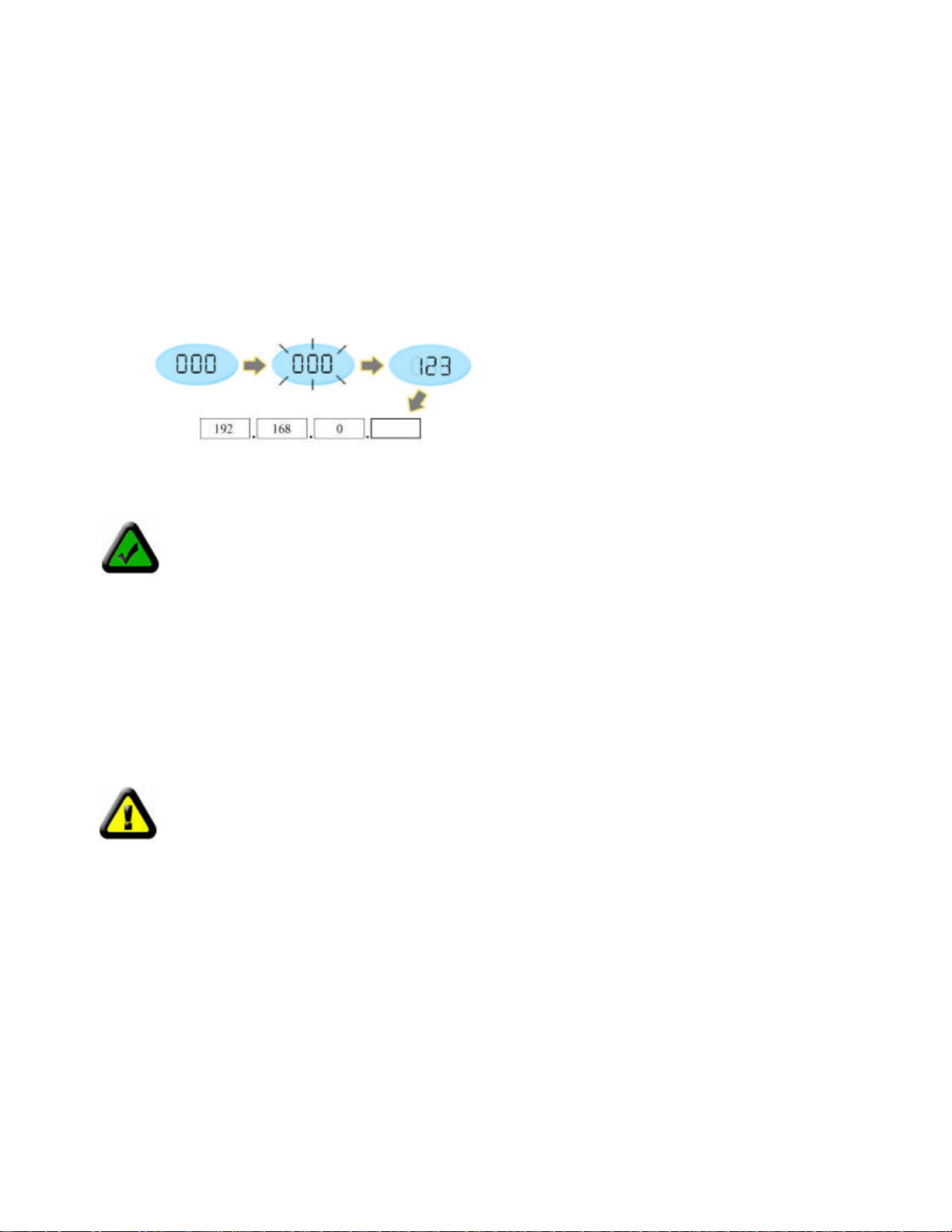
Step 4. Observe the status display on the side of the camera. If you’re using DHCP, the display will blink 000
while it’s requesting an IP address from your access point. If the display continues to blink --- the camera failed
to connect to your access point, please check that you have entered the exact SSID used by your access point.
If your network supports DHCP, the camera will acquire an address within a few seconds and the last three
digits will show on the display. If not, you’ll need to assign an address manually. If you assigned a static IP
address, the last three digits should show on the display.
After a few seconds your camera’s MAC address will show up in the list on the main window along with any
other cameras on the LAN.
Step 5. Select your camera from the list and you will see your camera’s IP address and other network settings
show up on the right side.
Note: Your camera’s MAC address can be
found on a sticker located on the bottom of
the camera. The number looks like
Page 12 of 69
000364017F3B.
Page 13
Step 6. Click the “Login” button to launch Internet Explorer and view the camera’s home page.
Step 7. Don’t forget to add the camera’s homepage to your favorites for easy access in the future.
Determining a Camera’s full IP address using the IP display
Other than the last 3 digits, all devices on a LAN share the same IP address. The portion of the address
common to all devices is known as the network address. Most home networks use either 192.168.0 or
192.168.1 for their network address. If you know your network address, you can simply combine it with the 3
digits shown on the camera’s display to determine the complete IP address of the camera. For example, if your
network address is 192.168.0 and the camera display is showing 020, the IP address for the camera is
192.168.0.20 (drop leading zeros). You can easily determine your network address by checking the IP address
of any PC on the network or using the Observer Setup Utility.
Using the IP display to determine your camera’s complete IP Address
Note: The Observer uses DHCP by default, meaning its address can change. You can assign a
static (fixed) IP address by selecting this option and changing the address manually. Refer to
Chapter 5: Observer Setup Utility for more information.
2.3 Mounting the Camera
The Observer can sit on a flat surface, such a shelf or bookcase, be mounted to a wall using the included
bracket, or mounted atop a tripod stand using the standard tripod mount located on the underside of the base.
When using the camera free standing, be sure to secure the cables. Failing to secure the cables could cause
the camera to be pulled off the mounting surface resulting in damage to the camera.
CAUTION: The camera should be mounted indoors or inside a weatherproof enclosure .
Outdoor exposure may result in damage and will void your warranty.
CAUTION: Don’t mount the camera with the lens facing into direct sunlight. Prolonged
exposure to direct sunlight will damage the sensor.
Wall Mounting
The mounting bracket included with your camera provides convenient mounting to vertical surfaces, such as
walls. The camera support platform can be tilted up or down to help point the camera toward your area of
interest. You can also rotate the camera in any direction on the platform.
Page 13 of 69
Page 14
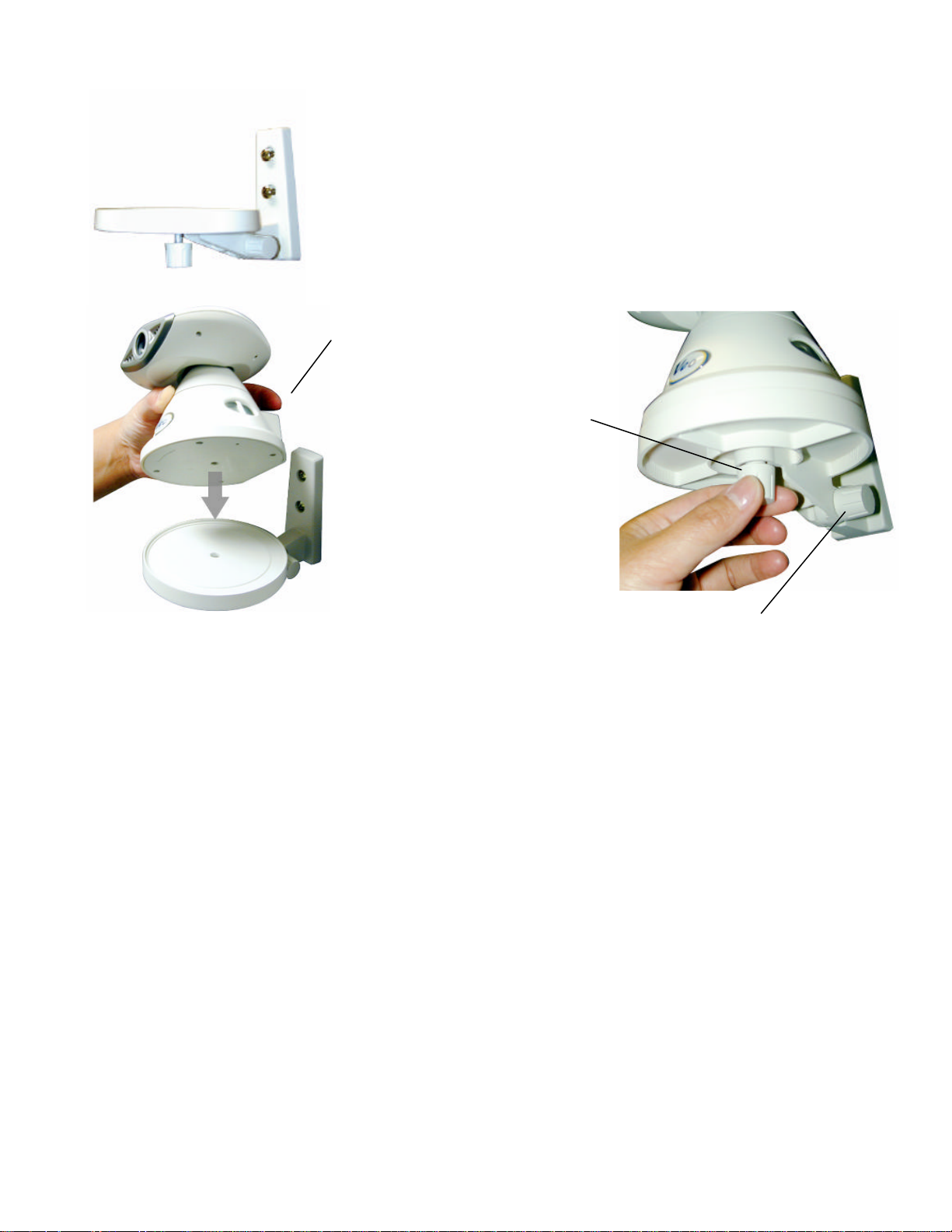
Step 1
. Find a suitable location to mount the camera.
Step 2. Using the mounting bracket as a guide, mark the location of the two
Step 8
. Loosen the tilt adjust thumbscre
w
observed.
mounting holes.
Step 3. Drill a ¼” hole for each screw.
Step 4. Use a hammer to tap the two plastic anchors into the holes.
Step 5. Use the two screws to fasten the bracket to the wall.
Step 6. Place the camera on the
mounting bracket platform and rotate
the camera to be facing in the desired
direction.
Step 7. Secure the camera to the
mounting bracket using the
thumbscrew located on the bottom of
the platform.
and tilt the camera toward the area to be
Page 14 of 69
Page 15
Chapter
3
Accessing the Camera
You can access Observer cameras from any Windows PC on your LAN. There are
two easy ways to access a camera, by browsing the camera’s on-board homepage
using Internet Explorer or using the included PC application Veo Observer Studio.
The browser method does not require any special PC software other than an ActiveX
control which is download and installed automatically. This gives you the freedom to
access cameras from anywhere on the Internet without needing to install any software. Observer Studio
provides powerful additional features such as multi-camera viewing and single click camera access.
The first time you access a camera you should use the browser method. Access to the camera’s configuration
pages, where you can change your username and password, are accessed from the homepage. With either
method, you will need to know about usernames and passwords first.
3.1 Usernames and Passwords
Note: The camera ships with one default username admin and password password (all lowercase).
It is strongly recommended that you change the password the first time you access the camera to
prevent unauthorized viewing. Refer to Appendix A: Restoring Factory Default Settings to reset
your username and password to the factory default settings if you forget your username/password.
Access to Observer cameras is password protected to ensure privacy. To access the camera you need a
username and password. There are three levels of access that can be assigned to each user:
1. Admin (Administrator) Administrators have full access to all the camera’s features and settings.
Administrator accounts should be reserved for those who need to change the camera’s configuration.
Note: Be sure not to give an admin username and password to anyone other than those who need it.
2. User (Normal user) People with user level usernames and passwords can access all the cameras
features but are not able to change any settings.
3. Guest. (Guest) Guests are only able to view the camera’s image. They cannot control the built-in pan
and tilt, take snapshots, or record video clips.
Please refer to Section 3.3: Camera Configuration for more information on setting up user accounts.
Note: Only one user may access the camera at a time and priority is given to the higher level user.
For example, if a normal user is accessing the camera and an admin level user logs on, the normal
user will be logged off. If a user of equal or lower level attempts to log in, they will be notified that the
camera is busy.
Page 15 of 69
Page 16
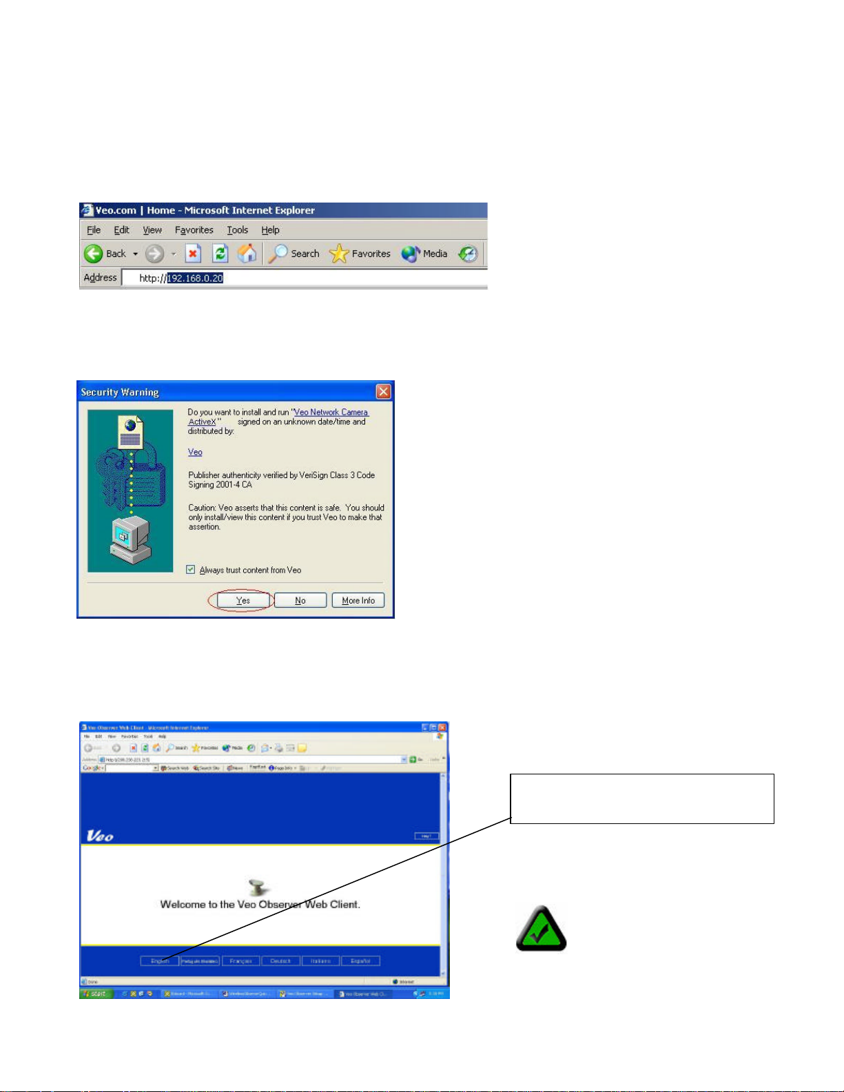
4. Click
English
to log in to the
3.2 Web Browser Access
1. From any PC on the local network, start Internet Explorer and enter the camera’s IP address in the address
bar, as shown below, then press Enter. For help on determining the camera IP address refer to Section 2.2:
Getting an IP address.
2. The first time you access the camera it will install an ActiveX control on your PC. You sho uld see a dialog like
the one shown here. If you don’t, your Internet Explorer security settings may prohibit downloading signed
ActiveX controls. Please restore the default security settings. For help configuring your Internet Explorer security
settings, see Appendix E: Internet Explorer Security Settings.
3. The camera’s welcome page will appear as shown below. If the welcome page does not appear or Internet
Explorer shows an error page, refer to the troubleshooting section in Appendix G: Frequently Asked
Questions, Troubleshooting, and Technical Support.
Page 16 of 69
camera.
Note: If the Observer
ActiveX control is not already
installed on your PC, you will
notice that it takes some
extra time for the page to
load. The Enter button won’t
appear until the page
finishes downloading.
Page 17
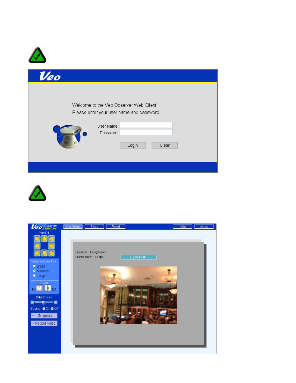
5. The camera login page will appear. Type in your username and password and click Login.
Note: The username and password are case sensitive.
Note: If another user is currently logged into the camera you may see a message letting you know
that the camera is busy. Priority is given to the highest level user. Refer to Section 3.1 Usernames
and Passwords for more information.
6. Once you are logged in, the main viewing page will open and the live video will start.
Page 17 of 69
Page 18
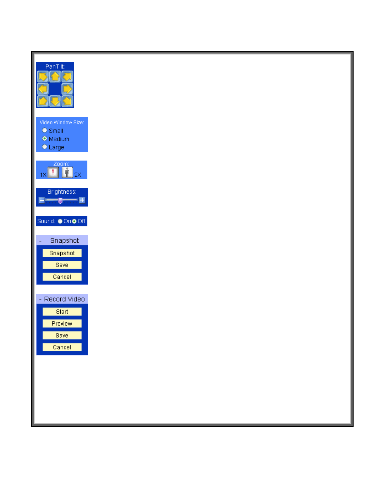
The following features are available on the Live Video page:
Clicking any of the yellow directional buttons will cause the camera to move one small
step in that direction. Click and hold the left mouse key down to make the camera
large step. When the camera reaches its end of travel, the buttons for that
Changing the window
e on your display and does not affect the image
being sent by the camera. Only an administrator can change the size of the image
for more
, and
to save the image
to stop capturing. Click
to save
the camera setup pages where you can access all of the camera’s
Resets the camera. Resetting has the same effect as turning the power off and then
Pan/Tilt
move one
direction are grayed out and disabled.
Video Window Size
Zoom
Brightness
Sound on/off
Snapshot
You can select one of the three available image sizes. Note:
size only changes the size of the imag
streamed from the camera. Refer to Section 3.3 Camera Configuration
information.
Use the Digital Zoom to zoom the picture 2X.
Adjusts the brightness level of the image.
Enables or disables audio monitoring.
Clicking on Snapshot will open a menu with three functions, Snapshot, Save
Cancel. Click Snapshot to capture the current image. Click Save
to your hard drive. Click Cancel to discard the image.
Record Video
Clicking on Record Video will open a menu with four functions, Start, Preview, Save,
and Cancel. Click Start to start capturing video. Click Stop
Preview to open Windows Media Player and playback the video. Click Save
the video to your hard drive. Click Cancel to discard the video.
Live Video Takes you back to the main viewing page.
Setup (admin only) Opens
configuration settings.
Reset (admin only)
on. Note: You must log in again after a reset.
Help Takes you to the Technical Support section of the Veo Observer website.
About Provides the version information.
Page 18 of 69
Page 19
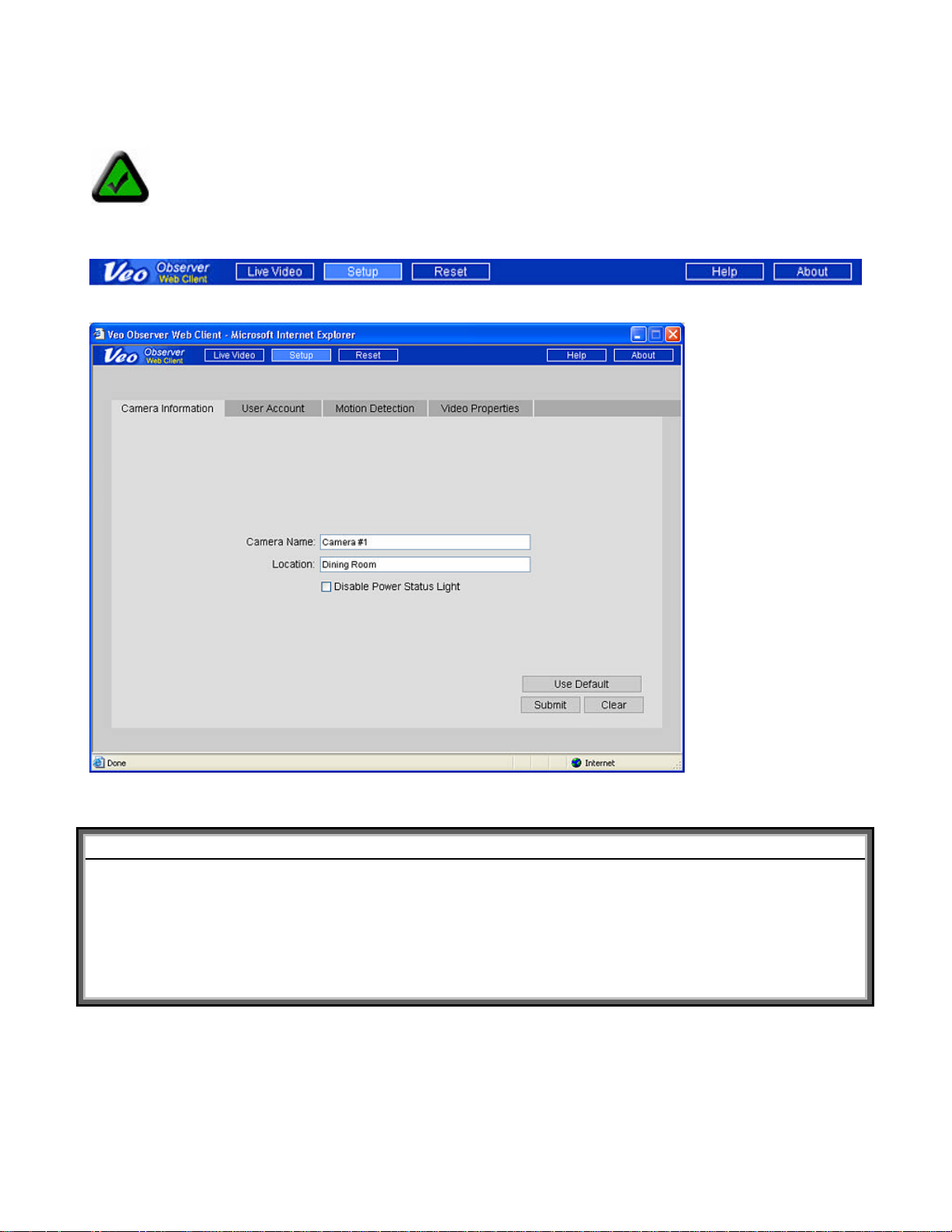
3.3 Camera Configuration
Note: You must be logged in as an administrator to access the camera setup pages.
1. Click the Setup button at the top of the main page to access the configuration pages.
Camera Information
The following settings are found on the Camera Information page:
Setting Description Valid Entries Default
Camera Name A name you assign to the camera
to help identify it. The name is
displayed on the main page.
Location Enter the camera location such as
front door, stock room, etc.
Disable Power
Status Light
Disables (turns off) the
power/status indicator light.
Up to 12 ASCII characters None
Up to 18 ASCII characters None
Enable/Disable Enabled
Page 19 of 69
Page 20

User Accounts
The User Account page is where you add and remove usernames and passwords. User accounts allow you to
control access to a camera. You should change the default username and password immediately and don’t give
this out to anyone. For everyone else, you should set up either User level accounts or Guest level accounts.
Adding a New User Account
Note: The first time you add a new account, it will automatically replace the default Admin account.
Therefore, the first account you add should be the Admin level account for yourself. You cannot use
admin for the new username. To restore the username and password to the factory defaults, refer to
Appendix A: Restoring Factory Default Settings.
Step 1. Enter the new username in the User Name box under New User. Usernames must be 4-12 characters
in length.
Step 2. Enter the Password for the new user. Passwords must be 4-12 characters in length.
Note: Usernames and passwords are case sensitive and can contain letters and numbers only.
Make sure to enter your username and password correctly when logging in.
Step 3. Retype the password into the Confirm Password box for confirmation.
Step 4. Select the user level as either Admin, User, or Guest.
Step 5. Click Add to add the new user.
To remove an existing user, select the username on the right side and click the Delete button. To modify an
existing user you need to remove the account and re-enter the information.
Page 20 of 69
Page 21
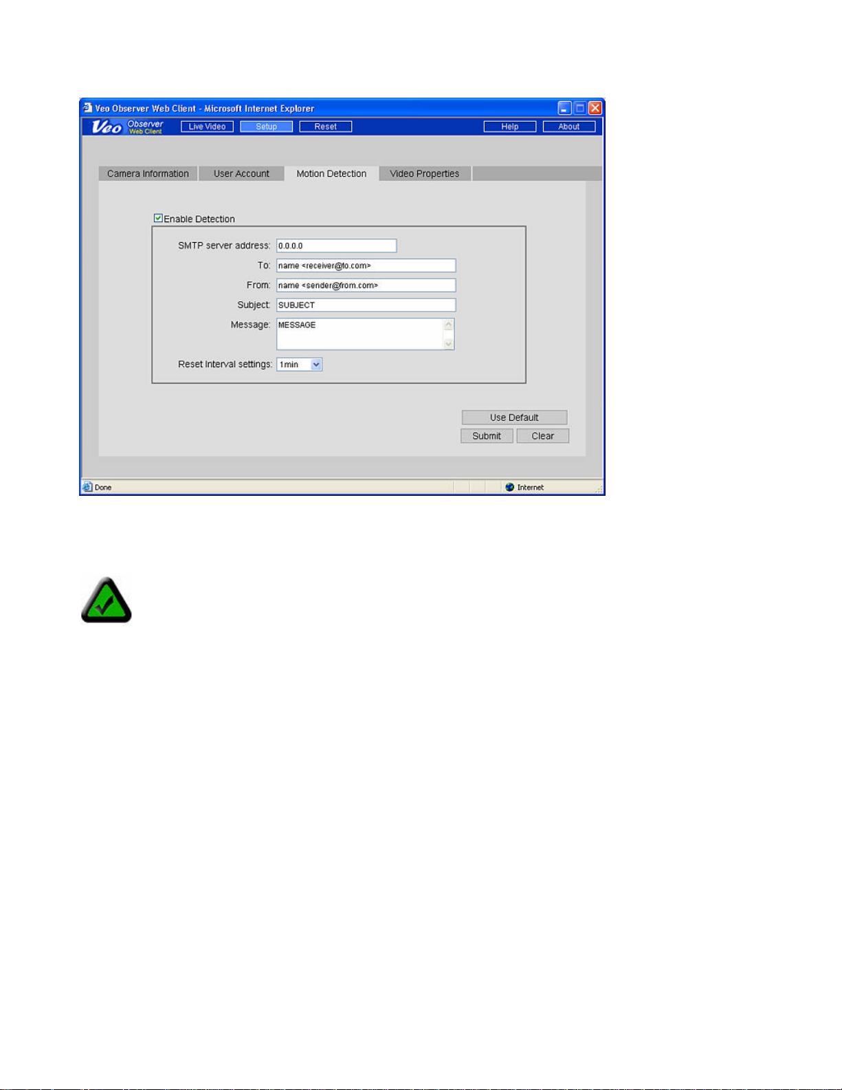
Motion Detection
The camera can be triggered by a motion sensor input to send you an email with a snapshot of the current
image attached. To enable this capability, check the Enable Detection checkbox and fill in the fields on the page
as described below:
Note: To enable motion detection you must first obtain the optional motion sensor and attach it to the
motion sensor jack of the camera. Refer to Appendix F: Motion Sensor Setup for more information.
SMTP server address
This is the IP address of the server you use to send mail. Almost all mail servers support this basic mail
protocol. Usually your Internet Service Provider (ISP) will provide you a server address for sending mail in the
form of a domain name such as “mail.ispname.com”. You can find this information from the email settings on
your PC or by consulting your ISP. From your mail server’s domain name, you can determine its IP address by
pinging the domain name and observing the reply. To ping your mail server click Start -> Run -> ping
mail.ispname.com. For more help with the ping command, refer to Appendix C.2: Using PING.
To
Enter the address for the mail recipient.
The format is Recipient Name <Recipient’sUsername@Recipient’sISP.com>
For example: john <john@earthlink.com>
From
Enter the address you use to send mail.
The form at is Your Name <YourUsername@YourISP.com>
For example: bob <bob@sbcglobal.net>
Subject
The subject for the email message. For example “Motion Detected! Camera 123”
Page 21 of 69
Page 22

Message
Any text message you wish to include in the body of the email.
Reset Interval
Sets the time interval, after an alert, before another detection event can occur.
Video Properties
Settings on this page affect the camera’s image size and quality and bandwidth consumed by the video stream.
Max. Frame Rate Sets the maximum frame rate that the camera can output. Note: Actual frame rate will
depend on the bandwidth (speed) of your connection.
Streaming Size Sets the resolution (size) of the image output by the camera. Reducing the streaming
size will significantly improve video performance (frame rate) when bandwidth is limited.
Lighting Conditions Improves video performance by configuring the camera for the appropriate lighting
conditions present in the camera view (scene). Use Backlight when the light source is
located behind the object you are trying to monitor. Use Night for very low lighting
conditions and Normal for all other situations.
Note: The camera cannot operate in total darkness. The minimum illumination is 1 lux, equivalent to
a very dimly lit room. Also, the camera should not be aimed into direct sunlight. Prolonged exposure
to direct sunlight can damage the sensor and will void your warranty.
Page 22 of 69
Page 23

PC Software Installation
4
In addition to a rich web page interface, the Veo Observer includes several powerful
PC applications which provide additional functionality.
To install the Veo Observer Studio software:
1. Insert the Installation CD into the CD-ROM drive. The initial screen will welcome
you to the installation process. Click Install to begin the software installation.
Chapter
Note: If the Veo Observer Installation screen does not appear, click on Start->Run and type in:
D:\AUTORUN in the Run dialog box and then click OK. (assuming that D:\ is your CD-ROM drive; if
not change it to the appropriate drive letter). If the Veo Observer Installation screen still does not
appear, consult your computer manual or manufacturer to locate the CD-ROM drive.
2. The installation procedure starts and you’ll see the Welcome dialog box. Click Next to continue.
Welcome Screen
Page 23 of 69
Page 24

3. You’ll see the License Agreement. Please read this agreement carefully. If you agree to the License
Agreement, click Yes to continue. If you do not agree and click No to the License Agreement, the software will
not be installed.
License Agreement Screen Choose Destination Location Screen
4. The next screen (Choose Destination Location) shows where the Veo Observer Setup Utility will be installed.
Click Next. (Optional: To install the Veo Observer Setup Utility in a different directory click the Browse button to
see the Choose Directory dialog box. Type a new path name for the files in the path box or select an existing
directory from the list.)
5. Proceed through the rest of the steps to finish the Veo Observer Setup Utility software installation and then
click Finish.
6. The next screen will install the Veo Observer Studio on your computer. Click Next to continue the software
installation.
Welcome Screen Choose Destination Location Screen
7. You’ll see the License Agreement. Please read this agreement carefully. If you agree to the License
Agreement, click Yes to continue. If you do not agree and click No to the License Agreement, the software will
not be installed.
8. The next screen (Choose Destinat ion Location) shows where the Veo Observer Studio will be installed. Click
Next.
9. Proceed through the rest of the steps to complete the Veo Observer Studio software installation process and
then click Finish. The software is now installed on your computer.
Page 24 of 69
Page 25

Observer Setup Utility
5
Step 2.
Click on your camera’s MAC address in
Step 1
. Click Start
-
> Programs
-
> Veo
-
>
Your PC’s network settings are shown
here. Since your PC should be connected
to the same LAN as the camera you are
network settings as the camera.
The Observer Setup Utility can be used to manually configure the camera’s network
settings. It may be necessary to use the setup utility to manually assign an IP address
for your camera if your network does not support DHCP. The utility is also very helpful
for finding all the cameras on your network.
Chapter
Note: The Observer Setup Utility must be run from a PC on the local
area network where the camera to be set up is located.
Observer Setup Utility or click the desktop
icon to run the program. The screen on the
left appears. The ut ility finds all the cameras
on the local network and shows their MAC
addresses in the list.
trying to set up, it will have almost the
same
Only the last three digits of the IP address
should be different.
the list. The camera’s current network settings
appear on the right side.
Note: The camera’s MAC
Refresh List Finds all cameras that are currently powered on
and connected to the LAN and update the list.
Login Opens the home page of the currently selected camera.
Set Apply the changes you’ve set to the selected camera.
address can be found on a
sticker attached to the
bottom of the camera.
5.1 Manually Assigning a Static IP Address
If your camera fails to obtain an address automatically by DHCP or you simply wish to ensure that the IP
address of a certain camera remains unchanged, you will need to assign a static IP address.
Note: Before you assign a static address to a camera, make sure no other device on your network is
configured to use the same address. If you aren’t sure if a particular address is in use, ping the
address and check to see if there is any response. For help using PING, refer to Appendix C.2:
Using PING.
Step 1. Select the Static option.
Step 2. Enter the IP address you wish to use. Make sure the first three sections are the same as the PC and
that the last three digits don’t conflict with any other device on the network.
Page 25 of 69
Page 26

Step 3. Enter the Subnet mask and Gateway. These settings should match the PC. Optionally, you may enter a
camera name to help identify this camera.
Step 4. Click Set. You will see a dialog prompting you to enter a username and password. You must enter a
valid admin username and password. Click OK to continue.
Step 5. You will see “Resetting camera…Please wait..” in the upper left corner. When the process is complete
you will see “Settings saved.” Click OK to continue.
Note: If you leave the IP address unchanged, you’ll see a message (shown below) informing you that there may
be another device using the same IP address (which in this case is the Observer). Click Yes to continue using
the IP address you specified.
The following tables will help you understand what each of the settings shown here means and how to configure
your camera so that it’s sure to be able to communicate with your PC.
PC Settings Table (The PC settings are shown to help you set up your camera and cannot be changed.)
Setting Description Notes
IP address PC’s address on the network
Only the last three digits should be different
for devices on the same LAN.
Subnet Mask Subnet that PC is on Should be the same for all devices on LAN.
Gateway
IP address of router or gateway that PC uses to
connect to the Internet
Should be the same for all devices on LAN.
Camera Settings Table
Setting Description Notes
Static/DHCP Sets the IP address mode
IP address Camera’s address on the network
Http Port Camera web page port
Subnet Mask Camera Subnet Use same setting as PC.
Gateway
Camera Name Name to help identify a camera
IP address of router or gateway that camera will
use to connect to the Internet
Use DHCP to obtain an address
automatically, static to enter a fixed address
The camera’s address should be set the
same as the PC except the last three digits
must be different.
This is always 80 unless you have multiple
cameras to access from the Internet. If so,
each camera needs its own web port such
81, 82, …
Use same setting as PC.
Camera name is stored onboard the camera
and displayed on the main web page.
5.2 Open a Camera’s Home Page
To open a camera’s home page, select its MAC address from the list and click Login. Internet Explorer is
automatically launched and directed to the camera you selected.
Page 26 of 69
Page 27

5.3 Updating the Camera’s Firmware
Step 1. Visit the Observer support website to
download the latest firmware (only if you are
experiencing problems with your camera ).
Place the files on your desktop or in another
folder which is easy to get to. If the files are
zipped (archived), you will need to unzip them.
Step 2. Run the Observer Setup Utility by
clicking the desktop icon.
Step 3. Select the camera’s MAC address in
the list box. You will see the camera’s current
firmware version appear at the bottom right.
Step 4. Click Update to start the firmware
update process.
Step 5. The dialog on the left appears prompting you for a
username and password. Enter a valid admin username and
password and click Update to continue. You may also click
Cancel to abort the update process or Check for Updates to go
to the Observer support site to check for firmware updates.
Note: An admin level user account is required to update the
camera firmware.
Step 6. A browse dialog appears prompting you for the location
of the new firmware file. Firmware files have a .bin file extension.
Navigate to the folder where you placed the downloaded files and
highlight the .bin file and then click Open.
Step 7. A warning message appears asking if you would like to continue. Click Yes to continue the update
process. If you need to abort the update process, click No.
Step 8. Another dialog box appears to let you know that the update process has begun. This process takes
several minutes and it’s very important not to disrupt the camera power during the download process. The
camera will display “301” in the IP Address LCD display window.
Warning: Do not unplug the camera’s power source or Ethernet connection
while the firmware is downloading. Doing so can disable your camera.
Step 9. When the download has completed you will see a dialog confirming the successful download. If the
camera is set to use DHCP, it will begin the process of acquiring a new address. When the address display
stops blinking and shows an address, the camera is ready to be accessed.
Page 27 of 69
Page 28

Chapter
6
The buttons along the top
Add
Add a camera to the list
Observer Studio PC Application
Veo Observer Studio is a suite of applications designed to enhance your Observer
experience. View Camera is where you can quickly connect to and control cameras
on your local network or anywhere over the Internet. You can also capture snapshots
and video to your PC and view up to four cameras at the same time on a single
screen. The other applications, Homepage Designer, Movie Maker, and Gallery,
provide powerful features for storing, organizing, editing, and sharing content captured
with Observer cameras.
To start the Veo Observer Studio you can double click on the desktop icon or go to Start -> Programs->
Veo-> Observer Studio. The application opens directly to the View Camera screen seen below.
of the main window allow
you to quickly navigate
between applications.
Home
Returns you to the main
window.
Homepage Designer
Opens the Homepage
Designer application.
Movie Maker
Opens the Movie Maker
application.
View Camera
Opens the View Camera
window to display the live
video from the camera.
View Gallery
Opens the album window
Observer Studio - View Camera screen
Before you can connect to a camera and start viewing it, you need to enter the camera’s connection information
into the Camera Manager. Once you’ve entered the information, you won’t need to type it in again.
6.1 Camera Manager
The Camera Manager keeps a list of Observer cameras, along with their IP addresses and login information,
allowing you to quickly connect to any camera in the list without having to type in the information.
where your snapshots and
video clips can be found.
Click the Camera Manager button to open the
Camera Manager.
Group Group multiple cameras together for login
Modify Change a camera’s connection information
Delete Remove a camera from the list
OK Accept changes and close
Cancel Close without saving changes
Page 28 of 69
Page 29

Add a Camera
port number, username, and password each time.
Hint
: If you forget the username and password for a camera, you can reset the camera to factory settings by
and the
Click the Add button to add a camera to the list. The following window appears:
Note: The information you enter here
doesn’t change any of the camera’s
settings. This information is kept on your
PC allowing you to connect quickly and
easily to any camera without re-entering the URL,
To change a camera’s IP address or port number,
use the Observer Setup Utility. To change
The default settings will appear in their corresponding boxes. Modify the settings as needed for the camera you
wish to connect to.
Camera Label A label used to help you to remember which camera this is. (12 character maximum)
URL IP address or domain name for the camera to connect to. (For example 123.45.67.123
or yourcameraname.dyndns.org) You don’t need to add http://, it’s done for you.
Web Page Port Always 80 unless you are accessing multiple cameras over the Internet.
User Name Your username for this camera.
Password Your password for this camera.
Remember Password Uncheck this option if you want to enter your password each time you log in.
OK Save changes and close window.
Cancel Discard changes and close.
usernames and passwords, go to the camera’s
home page and click Setup.
Note: Usernames and passwords are case sensitive and require 4 to 12 characters. No special
characters are allowed (ASCII characters only).
holding down the power button, while the camera is on, for 6 seconds. The default username is admin
default password is password.
Once you have entered the correct settings, click OK. The Add Camera dialog box closes and the camera’s
label appears in the Camera Manager list. Click OK to close the Camera Manager. You are now ready to
connect (log in) to the camera.
Page 29 of 69
Page 30

Group
Step 1
.
Click
Step 2.
Click on a
Click the Group button to set up a camera group to easily log in. Once you define a group of up to four
cameras, you can log in to the whole group with one click.
1. Select up to four cameras from the list on the left.
2. Click Select to add the cameras to the group.
3. Enter a Group Name in the text box at the top.
4. To remove a camera from the group, select it from the
list on the right and click Delete.
5. Click OK to save the group and exit or Cancel to exit
without saving.
Note: You can only log in to a group of cameras while in the multi-camera window. See the MultiCamera Viewing section for more information.
Modify Used to change the settings of a camera already added to the list.
Delete Removes a camera from the Camera Manager list.
OK Save changes and exit.
Cancel Close Camera Manager without saving changes.
6.2 Logging into a Camera
the down arrow
to display the
camera list.
The connection status dialog box appears as shown below.
As soon as the login process is complete the camera will begin to stream live video and all the camera controls
become active. Depending on the speed of your connection to the camera and the image streaming size, you
may experience varying amounts of delay before the image appears.
Note: If the status shows “No Response from
Camera,” the camera is either offline or you may
have entered an incorrect URL or port number.
Please check that the camera’s IP address or
domain name and port number match the
information you entered. Refer to the
Troubleshooting section in Appendix G for
help diagnosing connection problems.
camera from the list to
log in to it and begin
viewing.
Page 30 of 69
Page 31

6.3 Camera View Controls
When the camera reaches its limit
The camera’s location setting and average frame
rate are displayed beneath the image for your
reference only. The location setting can be
Drag the slider to the right to increase the image
brightness or to the left to decrease it. Allow
ds for the image to update to the
Pan and Tilt Controls: Click on any of the arrow buttons to move the camera one small step in the direction
indicated by the arrow. Holding down a button for a few seconds will move the camera one large step.
Note: The pan & tilt reaction time will depend on the speed of your connection. Slower connections,
especially long distance Internet connections, may introduce delays of up to a few seconds.
Digital Zoom Control
Brightness Control
Image Info
2X Click to zoom in on the image center
1X Click to return to normal viewing
several secon
new setting.
of travel range in any direction, the
buttons for that direction will be
disabled and their appearance will
change as shown here.
.
changed from the camera’s setup web page.
Note: The frame rate displayed will vary and may not match the camera’s frame rate setting. Actual
frame rate is dependent on bandwidth and network traffic. The rate displayed is averaged over
several seconds and is updated every few seconds.
Image Display Size Controls
The image display size buttons change the size of the image on your display by scaling the camera
image.
Note: The image size buttons do NOT affect the resolution (size) of the
image captured by the camera. The image resolution can be changed in
the camera’s setup web page. Because image resolution has a profound
effect on bandwidth consumpt ion and image quality, access is restricted
to camera administrators.
Page 31 of 69
Page 32

Click the speaker button to enable
Audio Controls
Audio Level Slider:
Move the slider
up to increase the audio input level.
Enabled Disabled
Settings
Only admin level user may access camera settings. The Settings button is not present when logged in as a
non-admin user. Click the Settings button to open the settings window.
or disable audio streaming.
Note: Enabling audio will affect video
performance in low bandwidth (Internet)
conditions. When not using audio, be sure
to leave it turned off for best video
performance.
Max. Frame Rate Sets the maximum frame rate that the camera can output.
Streaming Size Sets the resolution (size) of the image output by the camera. Reducing the streaming
Lighting Conditions Improves video performance by configuring the camera for the appropriate lighting
Overlay If your PC’s video graphics adapter supports hardware overlay, you can enable overlay
Use Defaults Restore all default settings.
OK Save changes and exit.
Cancel Discard changes and exit.
Snapshot
Note: Actual frame rate will depend on the bandwidth (speed) of your connection.
size will significantly improve video performance (frame rate) when bandwidth is limited.
conditions present in the camera view (scene). Use Backlight when the light source is
located behind the object you are trying to monitor. Use Night for very low lighting
conditions and Normal for all other situations.
Note: The camera cannot operate in total darkness. The minimum illumination is 1 lux, equivalent to
a very dimly lit room. Also, the camera should not be aimed into direct sunlight. Prolonged exposure
to direct sunlight will damage the sensor and will void your warranty.
for improved video performance.
Click the Snapshot button to capture the current image and save it to your PC. You’ll see a preview
of the image. Click Cancel to discard the image and return to the live view. Click Save to
save the image to your hard drive.
Page 32 of 69
Page 33

Recording a Video
Note: The captured video will be the same size (resolution) as the current streaming size. Changing
the display size using the image display controls does not affect the size of the captured video. Use
the Settings button to change the streaming size (requires admin level user).
1. Adjust the volume using the Audio Level Slider.
2. Click [Record] to record your video. Click the Stop button any time to end recording.
3. After the recording stops, the following buttons will appear on the bottom of the screen:
[Save Frame ] - Saves the current frame as a picture file.
[Trim Video] - Trim the video to the selected size and length.
Drag the sliders to select the new start point and end point of video
[Play] - Play the video.
[Cancel] - Discard the clip and return to live video.
4. Click to save your video.
Multi-Camera Viewing
Click the Views button to go to the multi-camera viewing window. If you are currently logged in to a
camera, its video appears at the top left of the multi-camera viewing area. You can now select up to
three additional cameras to log i n to from the drop down list at the top. If you have defined any camera
groups, you can log in to the whole group at once by selecting the group name from the list. The connection
status dialog will show the status of connecting to each camera and then eac h camera’s video will appear in one
of the other three video windows.
Enable Audio Click on a camera’s video window to select it. A yellow outline will appear around the window.
You may now enable audio for that camera by clicking the audio enable button. Click on another camera’s
window to hear its audio.
Refresh Click the Refresh button to refresh the camera screen.
Show/Hide Click the Show/Hide button to show or hide cameras that you have logged in to.
Layout Click the Layout button to change the layout of the multi-camera viewing area. The default is four
medium (320 x240) camera views on one screen. Changing this setting to One Camera View, will give one large
camera view on each screen and a vertical scroll bar will appear on the right side allowing you to scroll down to
see other camera views.
Views Click the Views button to return to the single camera viewing window. The currently selected camera
will be active. You will not be logged out of any other cameras you are logged in to.
Page 33 of 69
Page 34

6.4 Using the Gallery
Save the movie to
a
The Gallery is an album application you use to store and access snapshots and video clips captured with
Observer cameras. It can also manage other types of media for you such as sound bites and animations.
Note: You must first close the View Camera window before opening the Gallery.
Viewing Pictures in the Gallery
1. Click the View Gallery button. The Gallery Display Panel opens up.
2. Select a folder to view its content. The following are buttons and folders used in the Gallery Display Panel
along with their description:
[Min/Max Gallery] - Toggle button used to minimize or maximize the Gallery Display Panel.
[Thumbnail Size] - To change the size of the thumbnails displayed in the gallery.
[Sort By] - Sort the thumbnails by type, time, or name. You can also use this to search for a file in the
Observer Studio Gallery. When you are done searching, all the matched files will be stored in the Search
Results folder.
Folders:
Animations - Contains animated character files.
Photographs - Contains still pictures.
Graphics - Contains background graphics.
Videos - Contains video files.
Music - Contains audio clips.
Projects - Contains all your previously saved projects.
To display the details of a specific file, click [Properties].
Note: To delete a file, click on the file and click [Delete].
6.5 Movie Maker - Making or Editing a Movie
1. Click on the Movie Maker button on the Observer Studio Home Screen.
2. Choose Create A New Movie or Open An Existing Movie Or Project. If you choose to open an existing
movie, you can click on to display the following options:
specified location
3. Simply drag and drop videos or pictures from the Gallery Display Panel into the Movie Maker. The
following are buttons used in the Movie Maker along with their description:
[Back] Go back to the previous screen.
[Continue] Continue to the next screen.
[Save Finished Movie] Save your movie at any time in the process.
[ Preview Complete Movie] Preview the movie you have created.
Preview the movie
Page 34 of 69
Page 35

[Add A New Scene] Add a new video or picture to your movie. You can either add an
Delete the scene
Change the duration of
existing video/picture from your computer or record a new video/picture
from your Veo camera for insertion.
[Add Background Music] Add music to your movie.
[Remove Music] Remove music from your movie.
When you are done, click Continue.
Note: By default, still pictures will be shown in the movie for three (3) sec onds. To change the duration of
pictures in the movie or view other options, select your still picture and then click . The following box
will appear:
Select Scene Duration.
Note: Video (.avi) files also have a [Trim Video] button that allows you to adjust the size and length of the
Click Continue when you are done.
4. Select a scene from the bottom and click [Transition Effect].
5. Sample the effects by placing your cursor above each individual effect. Choose the opening effect (how one
scene changes to another).
6. Double-click on the remaining scenes in the Movie Maker, then repeat steps 4 and 5 above to apply opening
effects to the remaining scenes. Click Continue when you are finished.
7. Select a scene to edit by double-clicking on the scene in the Movie Maker. Make sure the scene shows up in
the Main Screen.
8. Edit the selected scene.
(See “Applying Text, Images, Videos, and Animated Characters” on Page 34 for more on editing a scene). Click
Continue when you are done.
9. Repeat steps 7 and 8 to edit the remaining scenes. When you are fin ished, click Continue.
10. a) To preview the complete movie, click [Preview ].
Edit the scene
Duplicate the scene
Set Duration
Save Changes
video. Refer to Page 28 for more information.
b) To save the movie for editing later, click [Save].
scene and other options
c) To save the movie as a separate file, click [Save As].
d) To save the movie on your computer, click Save Finished Movie.
Page 35 of 69
Page 36

e) To send your movie to a friend:
Click to go to the
Publish webpage to y
our ISP
Save webpage to
1) Click E-mail Movie To A Friend.
2) Type in the requested information.
3) The default name given to the movie is Default.wmv. To rename the movie before sending,
click on the words “Default.wmv” in the attachment text box and click [Rename].
4) Click to send your movie.
Note: Refer to Section 6.7: Configuring your E-mail Program to Send Files for instructions on how to
configure your E-mail program to send movies.
6.6 Homepage Designer - Designing a Home Page
1. Click on the Homepage Designer button on the Observer Studio Home Screen.
2. Choose to Create A New Homepage or Open A Previously Saved Homepage Project. If you choose to
open a previously saved homepage project, you may click on to get the following options:
3. If you are designing a new homepage, select a theme from the left panel, then select the background for your
homepage. Click Continue.
4. Edit your homepage. (See “Applying Text, Images, Videos, and Animated Characters” on Page 34 for more
information). To add a new page at any time, click [Add A New Page]. Click Continue when you are done.
5. Define your animated characters’ path. (For directions, please refer to Page 35.) Click Continue when you
are finished.
6. Select a picture or animated character.
the box to the left of the Link All Pages icon, it will turn into . It means that all your pages are
successfully linked. When you preview the webpage, you will see that there are two arrow buttons on the bottom
for easy navigation between pages. If you have text or pictures on the very bottom, they might be partly
covered. Try placing the text/pictures higher on the page.
previous page
your PC
[Link All Pages] - Check the box to the left if you want all pages to be linked. Notice that if you check
Click to go the next page
Page 36 of 69
Page 37

[Page Link] - Link an object/image/page to another page.
Anchor Actors
Linking to Another Page
If you want to include a function on your page that allows you to click on a text/picture to link to other web
pages, follow the steps below:
a) Select the text or picture on the Main Screen that you want to link .
b) Click on [Page Link].
c) Select to link to an existing page or to a page on the Internet. If linking to a page on the Internet, type in the
address (URL) of the website, then click OK.
Alternatively, you can click on [Actor Interaction].
container
Storyboard
cont ainer
Use the Up and Down buttons next to the Anchor Actors Container to select the image/text you want to link.
Then:
a) Drag a page from the bottom panel into the Storyboard Container to link to one of your existing pag es.
-OR-
URL – Link to a page on the internet
b) Click [URL], type in the address of the webpage on the Internet, then click OK.
Note: When using Homepage Designer, animated characters do NOT automatically move along its path by
default. You need to click on it in order for it to start. Refer to the next section on how to automate this
process.
Automating Animated Characters in Homepage Designer
a) Click [Actor Interaction].
b) Make sure the Anchor Actors Container has AutoPlay selected. If not, use the Up and Down arrows to
select it.
c) Select the animated character that you want to automate and drag it from the right panel into the Storyboard
Container. Repeat the same procedure for other animated characters. Click Exit when you are finished.
Autoplay
Page 37 of 69
Page 38

Full Internet Name
Enter default name of
7. Select the background music. Click [Set Background Music].
8. Choose your background music. To listen to the music before selecting, place your cursor on without
clicking. You may click [Mute] to turn the background music on and off.
Note: When you change the Mute button to , it does NOT remove the background music. You just will not
be able to hear it. To remove the music entirely, click [Set Background Music] and choose . After
you select your music, click Continue.
9. Select the opening effect by clicking [Transition Effect].
10. Choose the opening effect (how one page changes to another).
11. Double-click on the remaining pages in the Homepage Designer, then repeat steps 9 and 10 above to apply
the opening effect to the remaining scenes. Click Continue when you are finished.
12. a) To preview the page, click [Preview ].
b) To save the page for editing later, click [Save].
le, click [Save As].
13. Choose:
Add a New Page - To add and edit a new page.
-or Edit Next Page - To edit the next page.
-or Publish Now - To publish the homepage to your Internet Service Pro vider.
Publishing the webpage to your Internet Service Provider
To publish your webpage, you need to be connected to the Internet. Fill in the requested information, then click
Publish. You will be prompted to type in your user name and password to access the site for publishing.
Contact your Internet Service Provider for additional assistance if you are experiencing problems
publishing your webpage.
Site name
Enter sub -directory
New site
Edit selected site
Remove selected site
homepage
Publishing the webpage to your computer
a) Click on Publish The Files To The Hard Disk.
b) Select the destination and rename the file if desired. The webpage along with all supporting files (i.e. im ages,
music, etc.) will be saved as a folder instead of a single file.
c) Click View A Local Copy of the Page Just Published to view your webpage. Alternatively, you can open
the folder that you saved, and double-click on the file named index.
Note: DO NO T move or delete any items in the web folder. Otherwise, you might experience problems viewing
the pages.
Page 38 of 69
Page 39

Flip image upside
Display more
Return image to original
Applying Text, Images, Videos, and Animated Characters
Select font
Type text in here
Apply effects to fonts
Flip image
(mirror image)
Adding and Editing Text
a) Click [New Text] to add new text to the scene/page.
b) Double-click on the text to edit it. A screen similar to the one below appears:
Select font color
The following are the application buttons and their description:
[Insert Video] - Insert a new video clip.
Preview font
[Insert Image] - Insert a new image.
Alternatively, you can drag and drop images/videos from the Gallery Display Panel into the Main Screen.
[Animation Path] - Define the path of the images or animated characters (the path an object will follow
to move from point A to point B).
[Sequential Animation Sequence ] - Animations move one after another depending on which one
you inserted first.
[Simultaneous Animation Sequence] - All animations move at the same time.
Editing an Image or Animated Character
down
commands
horizontally
size
Drag to resize image
Page 39 of 69
Page 40

When you click , the following box appears:
Your selected
Adding Sound Effects to an Animated Character
You can add a sound effect to an animated character either by inserting a .wav file from the Sound Effects
folder and then click .
Note: Sound Effects are only applied when the animated character is moving along its defined path. If you
have not defined a path, the sound effect will be disabled.
Defining the Path of an Animated Character (also works with a still picture).
a) Select the image or animated character that you want to move.
b) Click [Animation Path]. Notice the animated character now follows the mouse cursor.
c) Select the starting point (where you want the animated character to start moving from). Hold the left mouse
button down, then freely drag the character along a path you specify to the ending point (where the character
finally stops at).
animated character
will follow this path
Page 40 of 69
Page 41

6.7 Configuring your E-mail Program to Send Files
In order to send your files directly from the Veo Observer Studio, you must change your default mail agent,
otherwise known as Messaging Application Program Interface (MAPI). For E-mail programs that do not support
MAPI (i.e. AOL, web-based E-mail pro grams), you need to attach the files manually. For further assistance on
how to attach files to your E-mail, contact your E-mail or web -based E-mail provider.
Using MAPI with Microsoft Outlook Express
1. Start Microsoft Outlook Express.
2. Go to Tools > Options.
3. Click Make Default under Default Messaging Programs - This application is NOT the default Mail handler.
4. Restart your computer.
Using MAPI with Microsoft Outlook
Microsoft Outlook automatically sets up your MAPI E-mail program during installation. Make sure your Microsoft
Outlook E-mail application is properly set up with the right POP account name, password, SMTP mail host
account, and other requirements. For further assistance, contact your Internet Service Provider (ISP) or
systems administrator.
Using America Online (AOL), Hotmail, or Yahoo! Mail
In order to send your pictures and videos from the Veo Observer Studio, you'll need to fol low the steps outlined
below if you are using America Online, Hotmail or Yahoo! Mail. The following steps require that you have
America Online 7.0 or higher or the latest version of MSN Messenger or Yahoo! Messenger installed on your
computer.
1. To send pictures/videos using America Online, Hotmail, or Yahoo! Mail, please follow the steps below,
depending on which version of Windows you are using:
If you are using Windows 98/Me: Click on Start ->Settings->Control Panel->Internet Options.
If you are using Windows 2000: Click on Start->Settings->Control Panel->Internet Options.
If you are using Windows XP: Click on Start ->Control Panel->Switch to Classic View->Internet Options.
2. Select the "Programs" tab.
Page 41 of 69
Page 42

3. Under "E-mail" select the e-mail provider that you normally use to send e-mail. (i.e. America Online, Hotmail,
Yahoo! Mail) Note: If you do not see America Online, Hotmail, or Yahoo! Mail listed under the “E -mail” section,
you’ll need to install the latest version of America Online (if using America Online [http://www.aol.com]) or MSN
Messenger (if using Hotmail [http://messenger.msn.com]) or Yahoo! Messenger (if using Yahoo! Mail
[http://messenger.yahoo.com]). Once the latest versions of the e-mail provider you use is installed, you’ll see the
options available.
4. After you have selected your e-mail provider, click the "OK" button and then clos e the Control Panel.
5. Sign on to America Online or connect to the Internet and log in to your web-based e-mail account.
6. Minimize America Online or web browser window (if using Hotmail or Yahoo! Mail).
7. By default, your pictures are saved in the 'Photographs' or 'Videos' folders in the Veo Observer Studio. To find
the pictures/videos for e-mailing, go to the 'C: \Program Files\Veo Observer Studio\Gallery' folder.
If you saved a picture (JPG), it will be located in the \Photographs folder. If you saved a Standard Video (AVI), it
will be located in the \Videos folder. If you saved a Video Mail (WMV), it will be located in the 'My Documents'
folder on your desktop.
8. After going to the corresponding folder for your picture/video, right -click on the picture/video you want to email and then select Send To->Mail Recipient.
9. This will automatically attach the picture/video to your e-mail. Note that most e-mail providers have a
maximum file size limitation for sending attachments, so if your picture/vi deo file size is too large, you may not
be able to send the picture/video. If this is the case, try using a smaller picture size or recording a shorter video.
10. In America Online, click the "Send Now" button or in Hotmail or Yahoo! Mail, click the "Send" button to send
your e-mail.
America Online – Sending E- mail
Hotmail – Sending E- mail Yahoo! Mail – Sending E-mail
Page 42 of 69
Page 43

Chapter
7
A
word about terminology
. Most home networks use a NAT (Network Address Translation) router as a
Accessing Cameras Over the
Internet
If your home or business LAN is connected to the Internet through a high speed
(broadband) Internet connection, with at least 128 kbps upload bandwidth, you can
access your cameras by web browser from anywhere on the Internet. To do this you
need to:
1. Know your WAN (Internet) IP address. This is the IP address that your Internet Service Provider gives
you to access the Internet. It may be static (always the same) or dynamic (can change from time to
time).
2. Make sure the two ports used by the camera (80 & 1600) are forwarded by your router or gateway to the
camera.
3. Make sure your camera’s default gateway is set to the LAN (local) IP address of your router/gateway.
7.1 WAN IP Address
The WAN (Wide Area Network) IP address that your Internet Service Provider grants you so that you can
access the Internet is very different from the LAN or local IP address that your PCs and cameras are using to
connect to your local network. Your WAN or Internet IP address is visible to the outside world (Internet) whereas
your local addresses are not. To find your home or business network from the Internet you must know your
WAN IP address.
Your WAN IP address is stored by your gateway router which uses it to connect to the Internet. All the devices
on your network connect to the Internet via your gateway router. You can find your current WAN IP address by
checking your router’s status page. There are also various websites such as www.whatismyip.com which will tell
you the IP address that you are currently using to access the Internet.
The term gateway is used generically to mean the device that connects a local network to the Internet. A
gateway may be a router, a PC running software which allows it to act as a gateway such as a proxy
server, or some other device
gateway. The term gateway router refers to such a device.
Static versus Dynamic IP address
The IP address (or addresses ) your ISP has provided you will either be static, which means it never changes, or
dynamic, meaning it can change periodically. Dynamic addresses present an additional challenge when trying to
locate your network from the Internet since your address may have changed since the last time you checked it.
How often your dynamic address changes varies from one service provider to another. Also, any time you
reboot your cable or DSL modem, your are likely to get a new address when reconnecting. The solution to the
ever changing IP address is known as DDNS or dynamic domain name service. A DDNS will allow you to find
your network by a domain name, such as mynetcam.no-ip.com, rather than needing to know the IP address.
Setting up a DDNS is covered in Section 7.6 Dynamic Domain Name Service (DDNS).
7.2 Network Address Translation (NAT)
Most home routers and business firewalls today perform something called NAT or Network Address Translation.
NAT translates your external or WAN IP address into an internal address inside your gateway router. What this
means is, you can think of your router as being divided into two halves, the LAN side (inside) and the WAN side
(outside or Internet side). When a connection request arrives at your router from the Internet, it will not get any
farther than the WAN side unless you have specifically instructed your router to pass this type of request to a
specific device on your LAN. This process is know as port forwarding or port redirecting.
Page 43 of 69
Page 44

7.3 Port Forwarding
All TCP/IP (Internet) networking uses software ports. Ports can be thought of as channels on your television. By
default, all web page traffic is on channel (port) 80. By default, the Observer uses port 80 to deliver its web page
to your browser and port 1600 to send video. Therefore, both of these channels (ports) must be open (not
blocked by your router/firewall) to incoming traffic in order for you to connect to the camera from the Internet.
Also, these two ports must be forwarded or redirected to the camera’s LAN IP address by your gateway router.
Your router’s setup software should provide a utility for port forwarding or redirecting. Appendix D: Router
configuration contains setup help for some popular home networking gateway routers currently on the market.
NAT and port forwarding for a typical home gateway router.
In the case shown in the illustration above, port 80 and port 1600 should be forwarded to IP 192.168.0.3.
Note: Forwarding ports to your camera does not pose any additional security risk to your LAN.
Before setting up port forwarding, it’s best to configure your camera to use a static LAN IP since your
port forwarding setup will need to be updated if the camera’s LAN IP address changes.
7.4 Default Gateway
Devices (PCs, cameras, etc.) on your network connect to the Internet via a gateway. For most home networks,
a NAT type router serves as the gateway. For business LANs, the gateway may be a PC running gateway
software. In order for any device on your network to get connected to the Internet, it must know the LAN IP
address of your gateway. If your camera is set up to use DHCP, then it will retrieve this information
automatically from your router.
However, if you have configured your camera to use a static IP address, you must also be sure that you have
set the correct gateway IP address in order to connect your camera to the Internet. Refer to Chapter 5:
Observer Setup Utility for more help on this topic.
Note: It may not be possible to test WAN (Internet) access to your cameras from a PC connec ted to
the LAN. To be sure that your cameras are accessible by the Internet, you should contact someone
you know with Internet access (preferable broadband) and have them enter your WAN IP address
into their browser.
Page 44 of 69
Page 45

You camera is now live on the Internet. Browsing your camera from the Internet is the same as browsing on
your LAN except that you must enter your WAN IP address (or camera domain name if you’ve set up a DDNS
service) instead of the LAN IP address.
7.5 Accessing Multiple Cameras over the Internet
When accessing multiple cameras over the Internet, you must assign separate port numbers for each camera.
The reason for this is simple. Your gateway router needs some way of knowing which camera to direct an
incoming request to. Unless directed otherwise, your browser will always send web page requests to port 80.
Since port 80 can only be forwarded to one LAN IP address, all incoming web page requests on port 80 will go
to this address.
The solution to this problem is to set up each camera to use a different port number (Refer to Chapter 5:
Observer Setup Utility for help setting a camera’s port number). For example, you may set up your second
camera to use port 81 for its web page. When you want to access this camera, you would tell your browser to
use port 81, instead of port 80. In your router’s port forwarding setup, you would need to forward port 81 to the
LAN IP address of the second camera. Web page requests arriving at port 81 will automatically be directed to
the second camera’s address.
To instruct your browser to use a different port, other than 80, to access a web page, you would add the port
number at the end of the IP address or URL, separated by a colon. For example, to access a camera on port 81
if your WAN IP address is 123.456.789.111, you would enter http://123.456.789.111:81 into your browser’s
address bar. You can do the same thing with a URL such as http://MyNetCam.DynDNS.org:81.
Note: Increasing the camera’s web page port number automatically increases it’s streaming port by
the same amount. For example, setting the web page port to 81 sets the streaming port to 1601.
You must forward both ports to the camera’s LAN IP address to enable remote access.
The steps to set up remote access are as follows:
1. Configure eac h camera to use a separate web page port such as Camera_1 = 81, Camera_2 = 82. Use
the Observer Setup Utility to do this.
2. Go to your gateway router setup page and configure port forwarding to port 81 and 1601 to LAN IP
address of Camera_1 and port 82 and 1602 to the LAN IP address of Camera_2.
3. From somewhere on the Internet, bring up Internet Explorer and enter your WAN IP address followed by
a colon and the port number such as: http://123.456.789.111:81 to access Camera_1.
Note: Some routers use port 80 for remote configuration and it’s possible to experience a conflict
when using port 80 for camera access. Therefore, you should use port 81 for your first camera, port
82 for the second, etc.. This setup also makes it easier to remember which camera is using a
particular port number.
7.6 Dynamic Domain Name Service (DDNS)
Your Internet Service Provider (ISP) provides you at least one IP address which you use to connect to the
Internet. The address you get may be static, meaning it never changes, or dynamic, meaning it’s likely to
change periodically. Just how often it changes, depends on your ISP. A dynamic IP address complicates remote
access since you may not know what your current WAN IP address is when you want to access your network
over the Internet. The solution to the dynamic IP address problem comes in the form of a dynamic DNS service.
Page 45 of 69
Page 46

The Internet uses DNS servers to lookup domain names and translate them into IP addresses. Domain names,
such as www.veo.com, are just easy to remember aliases for IP addresses. A dynamic DNS service is unique
because it provides a means of updating your IP address so that your listing will remain current when your IP
address changes. There are several excellent DDNS services available on the Internet and best of all most are
free to use. Two such services you can use are www.no-ip.com and www.DynDNS.org. You’ll need to register
with the service and set up the domain name of your choice to begin using it. Please refer to the home page of
the service for detailed instructions.
A DDNS service works by uploading your WAN IP address to its servers periodically. Your gateway -router may
support DDNS directly, in which case you can enter your DDNS account information into your router and it will
update the DDNS servers automatically when your IP address changes. Please consult your router’s
documentation for more information. If your router does not support DDNS, you can run a small client utility on
any PC on your network which will perform the updating. The client utility is usually provided for free by the
service. Check the service’s webpage for further information and terms and conditions.
Page 46 of 69
Page 47

Restoring Factory Default
A
Settings
Press and hold the Power button down for 6 seconds to reset the camera to the
factory defaults. You will see “300” displayed in the IP Address LCD display to
indicate that the camera has been reset. Release the Power button to reset the
camera.
Appendix
Note: You will need to reconfigure your camera settings after resetting the camera. The Veo
Observer will revert back to the factory default username (admin) and password (password ) if the
camera is reset. The network settings on your camera will also revert back to DHCP, thus, you may
need to reconfigure the camera using the Observer Setup Utility. Refer to Chapter 5: Observer
Setup Utility for directions on configuring the camera’s settings.
Page 47 of 69
Page 48

External Microphone
B
If you would like to use an external microphone (not included), you can attach any
standard 1/8” (3.5 mm) microphone to the Veo Observer’s external microphone
connection port located on the rear of the camera. Using an external microphone will
automatically disable the camera’s built-in microphone. The use of an external
microphone is recommended in noisy ar eas or if the camera is located far away from
the audio source.
Appendix
To use the external microphone, follow the steps below:
1. Turn off your camera and plug an external microphone into the external microphone jack.
2. Turn the camera back on and the cam era will automatically sense the external microphone and disable the
internal microphone.
3. You can now record or monitor audio using your external microphone.
Page 48 of 69
Page 49

Appendix
C
Network Utilities
Microsoft Windows includes various network information utilities to determine various
network configurations. To determine your IP address and network settings, follow the
steps below, depending on your operating system.
C.1 Determining your IP Address and Network Settings
Windows 98/Me:
1. Click on Start ->Run and type in: command and then press ENTER
2. In the MS-DOS window, type in: winipcfg and then press ENTER
3. This will display your network card’s Adapter Address, IP Address, Subnet Mask, and Default Gateway.
More information regarding WINIPCFG can be obtained by typing in: winipcfg /? at the MS-DOS prompt.
WINIPCFG is located in the C: \Windows folder.
Windows 2000/XP:
1. Click on Start ->Run and type in: command and then press ENTER
2. In the MS-DOS window, type in: ipconfig and then press ENTER
3. This will display your network card’s IP Address, Subnet Mask, and Default Gateway.
More information regarding IPCONFIG can be obtained by typing in: ipconfig /? at the MS-DOS prompt.
IPCONFIG is located in the C: \Windows\System32 folder.
C.2 Using PING
PING is a very useful utility for checking to see if a camera is responding or checking to see if an IP address is
available. In Windows 98/Me, PING is located in C:\Windows. In Windows 2000/XP, PING is located in
C:\Windows\System32.
Windows 98/Me/2000/XP:
1) Click on Start ->Run and type in: command and then press ENTER
2) In the MS-DOS window, type in: ping XXX.XXX.XXX.XXX and then press ENTER
(where XXX.XXX.XXX.XXX is your IP address) For example, if your Camera uses the IP address of
123.123.123.123, you would type in: ping 123.123.123.123
Page 49 of 69
Page 50

3) If there is a camera, or a PC or other network device online and using this address you will see:
Pinging 123.123.123.123 with 32 bytes of data:
Reply from 123.123.123.123: bytes=32 time<1ms TTL=128
Reply from 123.123.123.123: bytes=32 time<1ms TTL=128
Reply from 123.123.123.123: bytes=32 time<1ms TTL=128
Reply from 123.123.123.123: bytes=32 time<1ms TTL=128
Ping statistics for 123.123.123.123:
Packets: Sent = 4, Received = 4, Lost = 0 (0% loss),
Approximate round trip times in milli-seconds:
Minimum = 0ms, Maximum = 0ms, Average = 0ms
If there is NO response on this address you’ll see
Pinging 123.123.123.123 with 32 bytes of data:
Request timed out.
Request timed out.
Request timed out.
Request timed out.
Ping statistics for 123.123.123.123:
Packets: Sent = 4, Received = 0, Lost = 4 (100% loss),
This indicates that the address is available for use. However, there could still be a device which is currently
offline which is configured to use the add ress. To be certain, make sure all your network devices are on and
connected to your network when checking for address availability.
Page 50 of 69
Page 51

Appendix
D
Router Configuration
The following section describes the initial configuration of the router and port
forwarding for some of the most common routers from 3Com, Belkin, D-Link, Linksys,
Microsoft, NETGEAR, Proxim, Siemens, and SMC.
In order to access the Veo Observer/Wireless Observer from the Internet, you’ll need
to configure your router to use ports 80 and 1600 (default settings). Port 80 is used for
accessing the camera’s homepage and Port 1600 is used for authentication and video
streaming. If your Internet Service Provider blocks ports 80/1600, you’ll need to reconfigure your camera and
router to other po rts such as 81/1601, 82/1602, etc. To change the port settings on the camera, you’ll need to
use the Observer Setup Utility [Refer to Chapter 5: Observer Setup Utility].
Follow the steps below to configure your router, depending on the router manufacturer and model. If your
particular router manufacturer or model is not listed below, please contact your router manufacturer for further
assistance in configuring the router.
3Com (http://www.3com.com)
OfficeConnect Cable/DSL Gateway - [3C857-US]
OfficeConnect Wireless Cable/DSL Gateway - [3CRWE52196]
1) Log into your router.
2) On the main page, select Firewalls on the left side of the page.
3) Select the Virtual Servers tab at the top of the page.
4) Click New on the right side of the page to open the Virtual Server Settings dialog box.
5) Type in the camera's IP address in the Server IP Address text box. (Look on the Observer’s IP Address LCD
display for the last 3 digits of the camera’s IP address.)
6) Under Local Service, select Custom.
7) Under Custom Service Name, type in: VeoCam.
8) Under Specify Custom Service Ports, type in: 80, 1600.
9) Click Add to save the settings. The Observer should now be configured to work with your router and be
accessible from the Internet.
Belkin (http://www.belkin.com)
Wireless Cable/DSL Gateway Router - [F5D6230-3]
1) Log into your router.
2) On the main page, select Virtual Server on the left side of the page under the Security section.
3) Enter the following information on the page:
Line #1:
Private IP: Type in the camera's IP address. (Look on the Observer’s IP Address
LCD display for the last 3 digits of the camera’s IP address.)
Private Port: 80
Type: TCP
Public Port: 80
Line #2:
Private IP: Type in the camera's IP address. (Look on the Observer’s IP Address
LCD display for the last 3 digits of the camera’s IP address.)
Private Port: 1600
Type: TCP
Public Port: 1600
4) Click Enter to save the settings. The Observer should now be configured to work with your router and be
accessible from the Internet.
Page 51 of 69
Page 52

54g Wireless DSL/Cable Gateway Router - [F5D7230-4]
1) Log into your router.
2) On the main page, select Firewall on the left side of the page.
3) Under Firewall, select Virtual Servers.
4) Enter the following information on the page:
Line #1:
Enable: Checked in
Description: VeoWeb
Internet Port: 80 to 80
Type: TCP
Private IP address: Type in the camera's IP address. (Look on the Observer’s IP Address
LCD display for the last 3 digits of the camera’s IP address.)
Private Port: 80 to 80
Line #2:
Enable: Checked in
Description: VeoCam
Internet Port: 1600 to 1600
Type: TCP
Private IP address: Type in the camera's IP address. (Look on the Observer’s IP Address
LCD display for the last 3 digits of the camera’s IP address.)
Private Port: 1600 to 1600
5) Click Apply changes to save the settings. The Observer should now be configured to work with your router
and be accessible from the Internet.
D-Link (http://www.dlink.com)
DI-604/DI-614+/DI-624
1) Log into your router.
2) On the main page, click on Advanced at the top of the page.
3) On the left side of the page, click on Virtual Server. Note: Make sure DMZ host is disabled. If DMZ is
enabled, it will disable all Virtual Server entries.
4) Enter the following information on the page:
Enabled/Disabled: Enabled
Name: VeoWeb
Private IP: Type in the camera's IP address, for example: 192.168.0.3
Protocol Type: TCP
Private Port: 80
Public Port: 80
Schedule: Always
5) Click Apply to save the settings.
6) Enter the following information on the page:
Enabled/Disabled: Enabled
Name: VeoCam
Private IP: Type in the camera's IP address, for example: 192.168.0.3
Protocol Type: TCP
Private Port: 1600
Public Port: 1600
Schedule: Always
7) Click Apply to save the settings. The Observer should now be configured to work with your router and be
accessible from the Internet.
DI-704/704 P
1) Log into your router.
2) On the main page, click on Advanced at the bottom of the page.
3) On the Virtual Server page, enter the following information:
Page 52 of 69
Page 53

For ID #1:
Service Port: 80
Server IP: Type in the camera's IP address, for example: 192.168.0.3
Enabled/Disabled: Enabled
For ID #2:
Service Port: 1600
Server IP: Type in the camera's IP address, for example: 192.168.0.3
Enabled/Disabled: Enabled
4) Save your settings. The Observer should now be configured to work with your router and be accessible from
the Internet.
DI-714
1) Log into your router.
2) On the main page, click on Advanced Settings at the top of the page.
3) Click on Virtual Server Settings on the left side of the page.
4) Enter the camera's IP address into the Internal IP field. Under Service, select All and then click Submit to
save your settings. The Observer should now be configured to work with your router and be accessible from the
Internet.
DI-714P+
1) Log into your router.
2) On the main page, click on Advanced at the top of the page.
3) On the left side of the page, click Virtual Server.
4) Enter the following information on the page:
For ID #1:
Service Port: 80
Server IP: Type in the camera's IP address, for example: 192.168.0.3
Enabled/Disabled: Enabled
For ID #2:
Service Port: 1600
Server IP: Type in the camera's IP address, for example: 192.168.0.3
Enabled/Disabled: Enabled
5) Click Apply to save your settings. The Observer should now be configured to work with your router and be
accessible from the Internet.
Linksys (http://www.linksys.com)
EtherFast Cable/DSL Router - [BEFSR41]
Instant Broadband EtherFast Cable/DSL Firewall Router with 4-Port Switch/VPN EndPoint - [BEFSX41]
Wireless Access Point Router with 4-Port Switch - Version 2 - [BEFW11S4]
1) Log into your router.
2) On the router's main page, click on Advanced at the top of the page.
3) On the next page, click on Forwarding.
4) Enter the following information on the page:
Line #1:
Customized Applications: VeoWeb
Ext. Port: 80 to 80
Protocol: TCP
IP Address: Type in the camera's IP address, for example: 192.168.1.101
Enable: Checked in
Line #2:
Customized Applications: VeoCam
Ext. Port: 1600 to 1600
Protocol: TCP
IP Address: Type in the camera's IP address, for example: 192.168.1.101
Page 53 of 69
Page 54

Enable: Checked in
5) Click on Apply to save the settings. The Observer should now be configured to work with your router and be
accessible from the Internet.
Microsoft (http://www.microsoft.com/hardware/broadbandnetworking)
Wired Base Station - [MN-100]
Wireless Base Station - [MN-500]
1) Log into your router.
2) Open the Base Station Management Tool, and then click Security.
3) On the Security menu, click Port Forwarding, and then click Set up persistent port forwarding.
4) In the Description box, type a description of the server field such as: VeoCam
5) In the Inbound port box, type in: 80, 1600
6) In the Type box, select the protocol as TCP.
7) In the Private IP address box, type in the IP Address of the Observer network camera. For example, type in:
192.168.2.3
8) In the Private port boxes, type in: 80, 1600
9) Click Apply to save the changes you have made. The Observer should now be configured to work with your
router and be accessible from the Internet.
NETGEAR (http://www.netgear.com)
RP614 - Web Safe Router
MR814 - Wireless Router
1) Log into your router.
2) Click Advanced->Port Forwarding on the left side of the page.
3) Click Add Custom Service .
4) Enter the following information on the page:
Service Name: VeoWeb
Starting Port: 80
Ending Port: 80
Server IP Address: Type in the camera's IP address, for example: 192.168.0.3
5) Click Apply to save the settings.
6) Enter the following information on the page:
Service Name: VeoCam
Starting Port: 1600
Ending Port: 1600
Server IP Address: Type in the camera's IP address, for example: 192.168.0.3
7) Click Apply to save the settings. The Observer should now be configured to work with your router and be
accessible from the Internet.
MR314 - Cable/DSL Wireless Router
1) Log into your router.
2) Click Advanced on the left side of the page.
3) Click on Ports.
4) Enter the following information on the page:
Line #1:
Start Port: 80
End Port: 80
Server IP Address: Type in the camera's IP address, for ex ample: 192.168.0.3
Line #2:
Start Port: 1600
End Port: 1600
Server IP Address: Type in the camera's IP address, for example: 192.168.0.3
Page 54 of 69
Page 55

5) Click Apply to save the settings. The Observer should now be configured to work with your router and be
accessible from the Internet.
Proxim (http://www.proxim.com)
ORiNOCO BG -2000 Broadband Gateway
1) Log into your router.
2) On the router's main page, click on Setup at the top of the page.
3) On the left side of the page, click on Advanced Settings->Port Forwarding.
4) Check in the checkbox for Enable Port Forwarding.
5) Click New on the right side of the page.
6) Enter the following information on the page:
Global Port: 80
Local Address: Type in the camera's IP address, for example: 192.168.253.3
Local Port: 80
Type: TCP
7) Click Save to save the settings.
8) Click New on the right side of the page.
9) Enter the following information on the page:
Global Port: 1600
Local Address: Type in the camera's IP address, for example: 192.168.253.3
Local Port: 1600
Type: TCP
10) Click Save to save the settings.
11) Click Restart on the left side of the page to restart your router. The Observer should now be configured to
work with your router and be accessible from the Internet.
Siemens (http://www.speedstream.com)
SpeedStream 2602 - 2-Port DSL/Cable Router
SpeedStream 2623 - Wireless DSL/Cable Router
1) Log into your router.
2) After you are logged in, click on Advanced Setup->Virtual Servers.
3) Enter the following information on the page:
Line #1:
Private IP: Type in the camera's IP address. (Look on the Observer’s IP Address LCD
display for the last 3 digits of the camera’s IP address.)
Private Port: 80
Type: TCP
Public Port: 80
Line #2:
Private IP: Type in the camera's IP address. (Look on the Observer’s IP Address LCD
display for the last 3 digits of the camera’s IP address.)
Private Port: 1600
Type: TCP
Public Port: 1600
4) Click Enter to save the settings. The Observer should now be configured to work with your router and be
accessible from the Internet.
SpeedStream 2604 - 4-Port DSL/Cable Router
1) Log into your router.
2) After you are logged in, click on Advanced->Virtual Servers.
3) Under the Properties section, there are a few entries you'll need to add. Check in the checkbox for Enable.
4) Under the first box, next to the Enable checkbox, type in: VeoWeb.
Page 55 of 69
Page 56

5) Under PC (Server), select your camera or the camera's IP address from the list. If the camera is not listed,
select the link titled "My PC is not listed."
6) Leave Protocol as TCP.
7) Under Internal Port No type in: 80
8) Under External Port No type in: 80
9) Click on Add to save these settings.
10) Under the first box, next to the Enable checkbox, type in: VeoCam.
11) Under PC (Server), select your camera or the camera's IP address from the list. If the camera is not listed,
select the link titled "My PC is not listed."
12) Leave Protocol as TCP.
13) Under Internal Port No type in: 1600
14) Under External Port No type in: 1600
15) Click on Add to save these settings. The Observer should now be configured to work with your router and
be accessible from the Internet.
SpeedStream 2624 - Wireless DSL/Cable Router
1) Log into your router.
2) After you are logged in, click on Advanced->Virtual Servers.
3) Enter the following information on the page:
Line #1:
Private IP: Type in the camera's IP address. (Look on the Observer’s IP Address LCD
display for the last 3 digits of the camera’s IP address.)
Private Port: 80
Type: TCP
Public Port: 80
Line #2:
Private IP: Type in the camera's IP address. (Look on the Observer’s IP Address LCD
display for the last 3 digits of the camera’s IP address.)
Private Port: 1600
Type: TCP
Public Port: 1600
4) Click Enter to save the settings. The Observer should now be configured to work with your router and be
accessible from the Internet.
SMC (http://www.smc.com)
SMC2404WBR - Barricade Turbo 11/22 Mbps Wireless Cable/DSL Broadband Router
SMC7004VBR - Barricade Cable/DSL Broadband Router
SMC7004VWBR - Barricade Wireless Cable/DSL Broadband Router
1) Lo g into your router.
2) After you are logged in, click NAT on the left side of the page.
3) Click on Virtual Server on the left side of the page.
4) Enter the following information on the page:
Line #1:
Private IP: Type in the camera's IP address. (Look on the Observer’s IP Address LCD
display for the last 3 digits of the camera’s IP address.)
Private Port: 80
Type: TCP
Public Port: 80
Line #2:
Private IP: Type in the camera's IP address. (Look on the Observer’s IP Address LCD
display for the last 3 digits of the camera’s IP address.)
Private Port: 1600
Type: TCP
Public Port: 1600
Page 56 of 69
Page 57

5) Click Apply to save the settings. The Observer should now be configured to work with your router and be
accessible from the Internet.
SMC7004AWBR - Barricade 4-Port 11Mbps Wireless Broadband Router
1) Log into your router.
2) Click on Virtual Server on the left side of the page.
3) Enter the following information on the page:
For ID #1:
Service Port: 80
Server IP: Type in the camera's IP address. (Look on the Observer’s IP Address LCD
display for the last 3 digits of the camera’s IP address.)
Enable: Checked in
For ID #2:
Service Port: 1600
Server IP: Type in the camera's IP address. (Look on the Observer’s IP Address LCD
display for the last 3 digits of the camera’s IP address.)
Enable: Checked in
4) Click Save to save the settings. The Observer should now be configured to work with your router and be
accessible from the Internet.
Page 57 of 69
Page 58

Appendix
E
Internet Explorer Security
Settings
The Veo Observer web page communicates with the camera using a combination of
JavaScript and an ActiveX control. The ActiveX control must be downloaded from the
camera and installed on your PC. There are four things that your Internet Explorer
security settings must allow for the web page to work correctly.
1. Download signed ActiveX controls
2. Run ActiveX controls and Plug -ins
3. Script ActiveX controls marked safe for scripting
4. Active Scripting. (JavaScripts)
All these things are enabled by the default Internet Explorer Security settings. You can restore the default
settings in Internet Explorer by clicking Tools -> Internet Options -> Security -> Default Level.
You can also click Custom Level and set each of the four items listed above to “enable”. The default security
level in Internet Explorer is set to “Medium.”
CAUTION: You do not need to enable the option for downloading unsigned ActiveX controls.
Unsigned ActiveX controls may cause problems on your computer or allow hackers or a virus to be
installed on your system without your knowledge. Signed ActiveX controls have a digital signature
encoded in them verify the identity of the author (Veo).
Page 58 of 69
Page 59

Appendix
F
Motion Sensor Setup
By connecting the optional motion sensor to the camera’s motion sensor jack, you can
enable motion detection alert emails with an attached image. After connecting the
sensor as shown, you must configure the camera’s motion detection settings. Refer to
Section 3.3 Camera Configuration of the User’s Guide for further information.
Please visit http://www.veo.com/observer for information on purchasing the optional
motion sensor.
Mounting the motion sensor to the camera mounting bracket
The motion sensor mounts to the underside of the camera mounting brac ket. You need to first attach the metal
motion sensor mounting bracket to the backside of the sensor as follows:
1. Remove the sensor front cover by firmly holding the back half of the sensor housing and pulling the front
half outward.
2. Locate the two mounting holes on the backside of the sensor housing.
3. Align the two threaded holes in the metal sensor mounting bracket with the holes in the sensor housing.
4. Use the two screws included with the sensor bracket to attach the sensor housing to the bracket by
inserting the screws through the housing and threading them int o the bracket as shown.
With the sensor -bracket attached to the sensor you’re ready to attach the sensor-bracket to the underside of the
camera-mounting bracket as follows:
Wiring the sensor to the camera
CAUTION: Disconnect all power to the camera before making any conn ections.
1. Loosen the thumbscrew on the underside of the
camera-mounting bracket.
2. Align the slot in sensor-mounting bracket with the
thumbscrew hole in the bottom of the camera
mounting bracket.
3. Re-insert the thumbscrew through both brackets
and into the base of the camera as shown on the
left.
4. Rotate the sensor so that it’s facing the same
direction as the camera lens.
5. Tighten the thumbscrew (you may need to push
hard while threading the thumbscrew through the
camera mounting bracket base).
Page 59 of 69
Page 60

1. Locate the motion sensor connector at the rear of the camera. The holes for inserting the sensor wires
are labeled 1 through 4 from left to right.
2. Use a small screwdriver to depress and latch down the orange tabs over holes 1, 2 and 4.
3. Insert the red wire into hole #1 until the insulation just reaches the back of the camera.
4. Use the screwdriver to press down and release the orange tab above hole #1 locking the wire in place.
5. Repeat steps 3 & 4 for the white wire (hole #2) and the black wire (hole #4).
Wire Color Chart
Connector #1 Red
Connector #2 White
Connector #3 Not used
Connector #4 Black
The sensor is ready for use with the camera. Reconnect the power supply to the camera and turn the
camera on. Refer to Section 3.3: Camera Configuration of the User’s Guide for help configuring the
camera to work with the sensor.
Notes:
1. The range of the sensor is approximately 15 to 18ft and field of view is approximately 45 degrees.
2. There is a red LED behind the sensor lens which lights when the sensor is activated.
Page 60 of 69
Page 61

Frequently Asked Questions,
G
Troubleshooting, and Technical
Support
Problem or Question Resolution or answer
What username and password do I use
the first time I access the camera or after
a factory def ault reset?
What do I do if I can’t remember my
username and password?
The IP display continues to blink 000 and
doesn’t show an address after 1 minute.
The IP display blinks “---“
(Wireless Observer only)
The camera’s welcome page does not
appear when I try to browse the camera.
Username = admin, password = password (all lowercase)
Restore the factory default settings by pressing and holding down the
power button for 6 seconds. Note: Any configuration settings you
have entered will be lost.
1. Check the green Ethernet status LED at the back of the
camera. It should be on and will blink when network
communication is taking place. If not, check that both ends of
the Ethernet cable connection are secure.
2. Your network may not be configured for DHCP. Use the
Observer Setup Utility to manually configure the camera’s
network settings. Refer to Section 5.1 Manually Assigning
a Static IP Address.
The camera is not associated with an access point or Ad-Hoc peer.
1. Check that the camera’s SSID exactly matches your
access point or Ad-Hoc peer’s SSID (network name) (SSID
is case sensitive.)
2. Make sure the camera is within range of your access point.
3. If the camera is using Ad-Hoc mode, you’ll need to use a
static IP address for the camera. You can configure the
camera to use a static IP address using the Observer
Setup Utility.
LAN connection to camera:
1. Confirm that you are using the correct IP address and port
number using the Observer Setup Utility.
2. Use the Login button in the Observer Setup Utility.
Internet connection to camera:
1. Try to PING the camera’s IP address or domain name. See
Appendix C.2: Using PING for help. Note: You will not be
pinging the camera itself but rather the gateway/router
connecting the camera to the Internet. The gateway may be
configured not to respond to pings on its WAN IP.
2. Confirm that the camera’s gateway setting matches the LAN
IP of the gateway/router connecting it to the Internet. Refer to
Chapter 5: Observer Setup Utility for more help.
3. Confirm that the http port used by the camera (default = 80) is
forwarded to the camera’s LAN IP address in the
gateway/router’s configuration. Refer to Appendix D: Router
Configuration for more help.
4. Your Internet Service Provider may be blocking ports
80/1600. Reconfigure the camera to use ports 81/1601 using
the Observer Setup Utility. Make sure to make the
corresponding changes in your router.
5. Confirm that the camera can be browsed on the local
network.
Appendix
Page 61 of 69
Page 62

LAN connection to camera:
1. Check that the camera is on and that the Ethernet status LED
is on or blinking.
2. Cycle the power off and then on and re-check.
3. Confirm that the IP address of the camera does not conflict
with another device on the network by pinging the address
with the camera powered off.
Internet connection to camera:
The camera cannot be pinged.
Internet Explorer displays the following
message: “Your current security settings
prohibit downloading ActiveX controls”.
Internet Explorer shows: “Error on Page”
in the status bar in the lower left corner of
the webpage.
How can I tell if the camera’s ActiveX is
installed on my PC?
The camera ActiveX does not install
properly or cannot be installed.
When trying to log in to the camera, this
message appears: “Another user is
already logged onto the camera. Please
try again later.”
My browser does not seem to work too
well with the Veo Observer Web Client.
You have properly configured your
broadband router for port forwarding but
still cannot access the camera from the
Internet.
When you access the camera from the
Internet, you can reach the camera’s
welcome page but cannot log in. The
camera may indicate that the ports are
blocked.
What is the correct way to enter the
camera’s IP address if I have changed the
default port settings?
Can I access the camera via a VPN? This configuration is not supported with the Observer.
1. Confirm that IP address is correct. If you have a dynamic
address, it may have changed since you last checked it.
Refer to Section 7.1: WAN IP Address.
2. Since you are actually pinging the WAN IP of the
gateway/router connecting the camera to the Int ernet, make
sure that the gateway/router is configured to respond to pings
on its WAN IP.
3. Confirm that the camera can be pinged locally. If not, see
above.
Restore the default IE security settings (Medium) or configure the
individual settings to allow downloading and scripting of signed
ActiveX controls. Refer to Appendix E: Internet Explorer Security
Settings for more help.
Most likely, the camera ActiveX control did not download and install
correctly. Check your Internet Explorer security settings and then
close and restart Internet Explorer. Try to browse and log in again.
Go to C: \Windows\Downloaded Program Files and check to see if
there is an entry for the file XNC600NetCam Control. The status
column should show “Installe d”. If the file is not listed, make sure your
Security Settings in Internet Explorer are configured properly and then
try reloading the camera’s home page.
Install the Veo Observer Acti veX Control from the Veo Observer CD
ROM. Insert the Veo Observer CD ROM into your computer. Browse
to the “ActiveX for Web Client” folder on the CD ROM and then
double-click on the “Veo ActiveX.exe” program to install the camera
ActiveX. Once installed, try accessing the camera’s home page again.
Only one user may be logged in to a camera at one time.
Note: A higher -level user may displace a lower-level user.
Make sure that you are using Internet Explorer 5.0 or higher. If you
are experiencing problems, try upgrading to the latest version of
Microsoft’s Internet Explorer from the Microsoft webpage at:
http://www.microsoft.com/windows/ie
Your Internet Service Provider may be bl ocking ports 80/1600.
Reconfigure the camera to use ports 81/1601 using the Observer
Setup Utility. Make sure to make the corresponding changes in your
router. Refer to Appendix D: Router Configuration for more
information.
Verify that you have properly configured port forwarding for the
camera in your router’s settings. The camera uses port 80 (for we b
pages) and port 1600 (for authentication and video streaming). If you
can reach the camera’s welcome page, make sure that port 1600 is
also configured properly. Refer to Appendix D: Router
Configuration for more information.
In Internet Explorer, type in http://XXX.XXX.XXX.XXX:YY where XXX
is your IP address and YY is the port. For example,
http://123.123.123.123:81
Page 62 of 69
Page 63

Performance Issues
Your connection to the camera does not have enough bandwidth to
Slow frame rate
Blank screen or very slow video when
audio is enabled
Image is noisy or grainy
Audio is choppy
Pan/Tilt does not respond quickly
support a higher frame rate for the streamed image size. Try reducing
the video streaming size to 16 0x120 or 320x240 and/or disabling
audio.
Audio will consume 128 kbps and audio is always given priority over
video. Disable audio to improve or restore video.
Noise is signifi cantly increased in low light conditions. If possible,
increase the light on your subject.
Your Internet connection may not have enough bandwidth to support
streaming audio from the camera. Disable the audio streaming if the
sound is chop py or inaudible.
There may be a slight delay when you are using the Pan/Tilt feature
in conjunction with streaming audio and video. If you find that there is
a significant delay while panning or tilting the camera, try disabling the
audio streaming and/or reducing the video streaming size.
Technical Support:
While we hope your experience with the Observer network camera is enjoyable, you may experience some
issues or have some questions that this User’s Guide has not answered.
To obtain the latest information and support for your Observer network camera, please visit our webpage at:
http://www.veo.com/observer/support.asp for additional FAQ’s and troubleshooting tips.
You may also click the button in the Veo Observer Studio PC Application to go directly to the Observer
Technical Support section on the www.veo.com webpage.
When obtaining technical support, please make sure to have the following information handy:
Operating System:
Internet Explorer Version:
Router Brand/Model:
Broadband Internet Service Type (DSL/Cable Modem):
Broadband Internet Service Provider:
Page 63 of 69
Page 64

Appendix
H
Estimating Bandwidth
Consumption
Here is a guide to help you understand the bandwidth requirements for your camera.
Bandwidth is equal to the average frame data size in kilobits multiplied by the average
frame rate in frames per second. Frame data size, or the number of bits comprising a
single video frame varies a great deal from depending on scene complexity and lighting conditions. This is due
to the variable nature of JPEG image compression. Shown below are some average figures. Your results may
vary.
Image Streaming Size Average range of Data Sizes
160 x 120 32 - 48 kilobits
320 x 240 64 – 96 kilobits
640 x 480 320 – 480 kilobits
For example, streaming 4 fps of 160 x 120 video requires 128 to 192 kbps (kilobits per second). Therefore, with
a 128K upload connection; you will typically see 3 to 4 frames per second with 160 x 120 and 1 to 2 frames per
second with 320 x 240.
Note: Audio streaming requires 128 kbps. Most DSL/Cable modem upload speeds may not
even reach up to 128 kbps. Thus, you may not be able to receive any video while streaming
audio on a 128 kbps connection.
For optimal video performance, disabling audio streaming will result in the best
performance.
Page 64 of 69
Page 65

Technical Specifications
I
Veo Observer Network Camera Technical Specifications
Resolution VGA (640 x 480)
Type CCD
Color depth 24 bit
Streaming Sizes 160 x 120, 320 x 240, 640 x 480
Image
Lens
Pan-Tilt Range
Network Connection Ethernet RJ-45, 10/100 baseT
Audio Sampling 8 kHz, mono, 16 bit PCM
Power Voltage 5 VDC
WLAN
Compression Motion JPEG (in hardware)
160 x 120 10 fps
Frame rate
Sensitivity 1 lux
Aperture F2.0
Construction 5 element, all glass
Type Fixed Focus
Enclosure Indoor use only
Max. Humidity 80% Environmental
Operating Temperature
Wireless Observer
Network Interface standard 802.11b (WiFi)
Connection Modes Infrastructure or Ad-Hoc
Range At least 300ft (open environment)
WEP encryption 64 or 128 bit
Frequency 2.4 GHz Direct Sequence Spread Spectrum
Channels 1-11 (N.America), 1-14 (Japan), 1-13 (Europe, ETSI)
320 x 240 10 fps
640 x 480 5 fps
120° pan (+/- 60 °), 60° tilt (+/- 30°)
32 to 122° F (0 to 50° C)
Appendix
Page 65 of 69
Page 66

Glossary
Term Explanation Relates to camera how
802.11b IEEE standard for wireless networking devices.
Peer to peer network. Method for directly connecting
Ad-Hoc
DDNS
DHCP
Display size
DNS
Gateway
Gateway-Router
Image resolution The number of pixels captured in an image.
IP address
ISP Internet Service Provider
LAN
LAN IP address
MAC address
NAT
Network address
Router A device that routes traffic on a network. Provides LAN infrastructure.
devices on a wireless network to each other without
an access point. Each device must use a static IP.
Dynamic Domain Name System. DNS service which
self-updates periodically to deal with changing IP
addresses.
Dynamic Host Configuration Protocol. Allows
network connected devices to set their IP address,
default gateway, and subnet mask automatically.
Most home networking routers support DHCP.
The number of pixels used to display an image on
your monitor. Display size may be different than
image resolution.
Domain Name System. Lookup service that
translates domain names into IP addresses.
A device which connects one network to another. Provides Internet connection.
A combination device that allows multiple devices on
a LAN to connect to the Internet using one WAN IP
address. Most home networking routers are also
gateways.
Unique number used to identify each device on a
TCP/IP network.
Local Area Network. A group of computers, printers,
cameras, and other network connected devi ces
which share a common network address such as
192.168.0.X
Term used to differentiate a local address from the
WAN IP address used by a gateway router.
Media Access Control address. A unique hardware
identifier for each network device.
Network Address Translation. The process of
“translating” one WAN IP address into multiple LAN
IP addresses. Most home networking routers user
NAT to create LAN IP addresses.
The first 9 digits of the IP address of any device
connected to a TCP/IP LAN. You can find out your
network address by checking the IP address of any
PC on the network.
Wireless Observers are
interoperable with 802.11b devices.
You can connect to a Wireless
Observer directly from a PC with a
wireless network interface card
using Ad-Hoc mode.
If you don’t have a static IP address,
you need a DDNS to simplify
remote access.
Allows camera to auto configure for
a network.
The small, medium, and large
buttons on the main page change
this setting.
If you want to access cameras by
convenient name instead of an IP
address, you need to register a
domain name.
Provides the network to connect
cameras and allows cameras to be
connected to the Internet.
Found on the settings web page.
Each camera must have a unique IP
address.
Provides your WAN IP address for
Internet access.
Cameras must be attached to a
LAN.
Camera use a LAN IP address to
communicate with your LAN.
Allows the network to distinguish
between multiple cameras on the
network, similar to a serial number.
Translated addresses cannot be
seen directly from the Internet. Port
forwarding is required.
Combine the three digits on the
camera display with your network
address to get the camera’s full IP
address.
Page 66 of 69
Page 67

SSID
SMTP
TCP/IP
URL
WAN
WAN IP address
WAP
WLAN Wireless LAN (Local Area Network).
WEP
Service Set Identifier. A unique name shared among
all devices on a wireless network.
Simple Mail Transfer Protocol.
Transmission Control Protocol/Internet Protocol. The
most common communication protocol for Ethernet
networking and all of the Internet.
Uniform Resource Locator. The complete
specification that your web browser needs to locate a
resource (web page or other) on any TCP/IP
network.
Wide Area Network. Several LANs which are
interconnected.
External address used by a gateway -router to
connect your LAN to an outside network (the
Internet). This is the IP address or addresses
provided by your ISP that you use to connect to the
Internet.
Wireless Access Point. Provides a connection point
between wired and wireless networks and
interconnects wireless devices in infrastructure
mode. Sometimes combined with a NAT
router/gateway.
Wired Equivalent Privacy. Standard for encrypting
data sent over a wireless (802.11b) network.
The Wireless Observer uses this
setting to determine which network
to connect to.
The camera sends email with this
protocol.
Used to communicate with PC
clients.
Your camera’s URL looks like
“http://IP address:port number”. The
port number is 80 by de fault.
When you connect to the Internet,
you form a WAN with your ISP’s
network.
You must know the WAN IP
address you are using to connect to
the Internet to access cameras
remotely over the Internet.
Cameras using infrastructure mode
will connect to a WAP.
Wireless Observers connected to
your WLAN.
Traffic on a wireless network may
be intercepted. WEP makes it
difficult to decipher intercepted data.
Page 67 of 69
Page 68

Warranty
Veo Statement of Limited Warranty
Veo warrants this product to be free from defects in material and workmanship for a period of (2) years from the
date of original purchase. If this product proves to be defective in material or workmanship during the warranty
period, Veo will, at its sole option, repair or replace the product with a similar product. Replacement product or
parts may include remanufactured or refurbished parts or components.
Who the warranty protect s:
This warranty is valid for the original consumer purchaser only.
What the warranty does not cover:
• Any Veo product on which the serial number has been defaced, modified or removed.
• Damage, deterioration or malfunction resulting from:
§ Accident, misuse, neglect, fire, water, lightning, or other acts of nature, unauthorized product
modification, or failure to follow instructions supplied with the product.
§ Repair or attempted repair by anyone not authorized by Veo.
§ Any damage of the product due to shipment.
§ Removal or installation of the product.
§ Causes external to the product, such as electric power fluctuations or failure.
§ Use of supplies or parts not meeting Veo's specifications.
§ Normal wear and tear.
§ Any other cause which does not relate to a product defect.
• Removal, installation and set -up service charges by any third party.
• Costs associated with shipping and/or transporting the product for repair, replacement, or exchange.
How to get service :
For information on obtaining warranty service, fill out a technical support form on the Veo web site, located
on our webpage at: http://www.veo.com/support.asp.
To obtain warranty service, you will be required to provide:
• A copy of the original dated sales slip or sales invoice
• Your name
• Your address
• The serial number of the product
• A description of the problem
A Technical Support Representative will determine if your problem is covered under this warranty agreement. If
the problem is covered, you will be issued a Return Merchandise Authorization number (RMA) with specific
instructions regarding how the product must be returned to Veo for repair or replacement.
At this time, replacement or repaired products can only be sent to U.S. addresses. Products cannot be sent to
P.O. boxes.
Limitation of implied warranties:
THERE ARE NO WARRANTIES, EXPRESS OR IMPLIED, WHICH EXTEND BEYOND THE DESCRIPTION
CONTAINED HEREIN INCLUDING THE IMPLIED WARRANTY OF MERCHANTABILITY AND FITNESS FOR
A PARTICULAR PURPOSE.
Page 68 of 69
Page 69

Exclusion of damage s:
VEO'S LIABILITY IS LIMITED TO THE COST OF REPAIR OR REPLACEMENT OF THE PRODUCT. VEO
SHALL NOT BE LIABLE FOR:
• DAMAGE TO OTHER PROPERTY CAUSED BY ANY DEFECTS IN THE PRODUCT, DAMAGES
BASED UPON INCONVENIENCE, LOSS OF USE OF THE PRODUCT, LOSS OF TIME, LOSS OF
PROFITS, LOSS OF BUSINESS OPPORTUNITY, LOSS OF GOODWILL, INTERFERENCE WITH
BUSINESS RELATIONSHIPS, OR OTHER COMMERCIAL LOSS, EVEN IF ADVISED OF THEIR
POSSIBILITY OF SUCH DAMAGES.
• ANY OTHER DAMAGES, WHETHER INCIDENTAL, CONSEQUENTIAL OR OTHERWISE.
• ANY CLAIM AGAINST THE CUSTOMER BY ANY OTHER PARTY.
Effect of local law:
This warranty gives you specific legal rights, and you may also have other rights which vary from locality to
locality. Some localities do not allow limitations on implied warranties and/or do not allow the exclusion of
incidental or consequential damages, so the above limitations and exclusions may not apply to you.
Page 69 of 69
 Loading...