

Page 1
V ENTURE L IGHTING’S LED ROUNDBACK F LOOD
USER MANUAL
STOP
Before You Begin
Read These Instructions Completely and Carefully
Upgrade Instructions: Slipfitter Mount
STEP 1: Disconnect power from the luminaire and follow proper lockout/tagout procedures before beginning installation or
maintenance.
STEP 2: Remove the existing luminaire. Dispose of the lamp(s) and ballast(s) per local requirements.
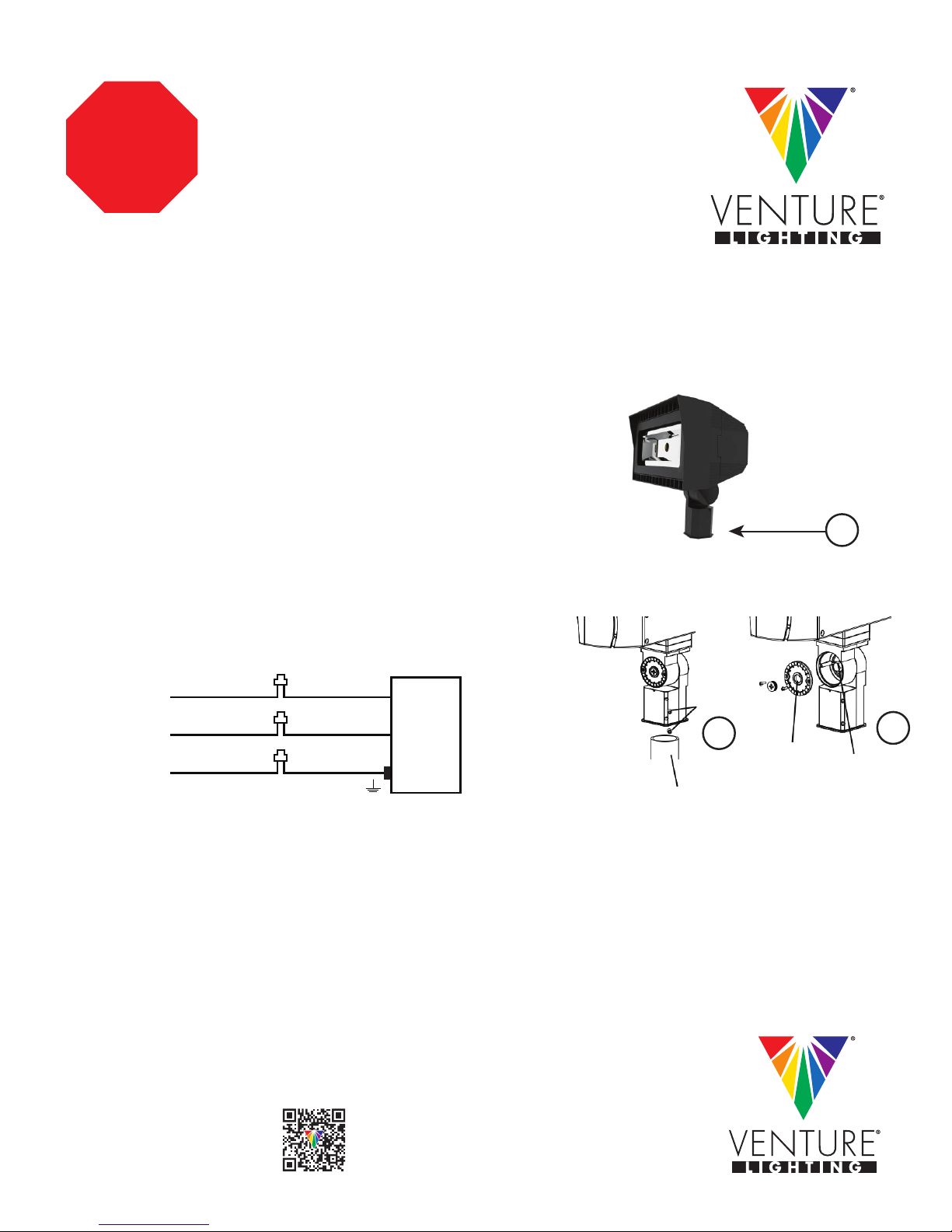
STEP 3: Slipfitter mount fits a 2 3/8” OD tenon (A).
STEP 4: Place slipfitter over the tenon and secure the fixture using the set
screws (B) on the side of the slipfitter.
NOTE: Take note NOT to pinch any wires when closing the wiring enclosure.
STEP 5: To adjust the aim of the fixture, remove the round cover plate. (C)
A
STEP 6: Loosen the locking bolt, aim the fixture as desired and then tighten the
locking bolt. Secure the round cover plate. (C)
STEP 7: Connect the fixture input leads (D) to the supply wire leads.
(D)
Wiring Diagram
(+) LINE
(-) COMMON
GROUND
BLACK
WHITE
GREEN
LIGHT
FIXTURE
Tenon
Set Screws
B
Round
Cover
Plate
Locking
Bolt
C
STEP 8: Each fixture is supplied with a twist lock shorting cap. For the fixture to function, the shorting cap MUST be installed.
Note: An accessory twist lock photocell may also be installed in place of the shorting cap.
STEP 9: Power can now be restored to the fixture.
(877) 281-1233
Fax: (877) 294-2829
2451 Enterprise Parkway East
Twinsburg, Ohio 44087 USA
E-mail: venture@adlt.com
VentureLighting.com
© 2016 Venture Lighting International • Venture Lighting is a registered trademarks of Venture Lighting International.
AV0004-A
Page 2

V ENTURE L IGHTING’S LED ROUNDBACK F LOOD
USER MANUAL
ARRÊT
Avant que tu commences
Lisez ces instructions complètement et attentivement
Instruction de mise à niveau: Slipfitter Mount
1: Coupez l'alimentation de l'appareil d'éclairage et de suivre les procédures de verrouillage / débranchement avant de commencer
l'installation ou l'entretien.
2: Retirez le luminaire existant. Jeter la lampe (s) et le ballast (s) conformément aux exigences locales.
3: Montage Slipfitter fait sur un tenon avec un diamètre extérieur de 2 3/8".
4: Placez Slipfitter sur le tenon et fixer l'appareil en utilisant les vis de réglage (B)
sur le côté de la Slipfitter.
REMARQUE: Prenez note de ne pas pincer le fil lors de la fermeture de
l'enceinte de câblage.
5: Pour régler la position de l'appareil, retirer la plaque de couvercle rond. (C)
A
6: Desserrer le boulon de verrouillage, positionner l'appareil comme souhaité, puis serrer la vis de blocage. Fixer la plaque de
couvercle rond. (C)
7: Connecter le fil d'entrée de fixation (D) aux fil conducteurs d'alimentation.
(D) Schéma de câblage
(+) LIGNE
(-) COMMUN
SOL
8: Chaque appareil est livré avec un capuchon de court-circuit twist-lock. Le capuchon court-circuit doit être installé pour l'appareil
de fonctionner.
Remarque: Un accessoire photocellule de serrure de torsion peut également être installé à la place du bouchon de court-circuit.
9: La puissance peut maintenant être restauré à l'appareil.
NOIR
BLANC
VERT
LUMINAIRE
tenon
vis de réglage
B
plaque
de couvercle
rond
C
boulon
de verrouillage
(877) 281-1233
Fax: (877) 294-2829
2451 Enterprise Parkway East
Twinsburg, Ohio 44087 USA
E-mail: venture@adlt.com
VentureLighting.com
© 2016 Venture Lighting International • Venture Lighting is a registered trademarks of Venture Lighting International.
AV0004-A
 Loading...