

Venture Cycle LandRider Assembly Instructions Manual

ASSEMBL Y INSTRUCTIONS
Version 4

ASSEMBLY TIPS
If you carefully follow each step in order, assembly should take approximately 30 minutes.
We recommend that you have a friend help you assemble the LandRider .
Relax and be patient. Your safety is important.
CUSTOMER SERVICE
If you have any questions please call LandRider at: 1-800-945-5335 or email us at
service@landrider .com
WARNING: These Assembly Instructions are a supplement to your Owner’s Manual.
This information is limited to the assembly instructions for the LandRider and does
not include general safety and product information on the LandRider or bicycling.
For a complete understanding of the LandRider and all warnings and cautions, you
must thoroughly read and completely understand your LandRider Owner’ s Manual.
Copyright: Venture Cycle, LLC. 2001
1
STEP 1: ASSEMBLY PREPARATION
A) Using a pair of scissors, carefully cut all the ties holding the bike parts together .
DO NOT USE A BLADE, AS THIS IS DANGEROUS AND COULD PUNCTURE THE TIRE.
B) Carefully free Front Wheel which is supported by Crank Arm and Handlebar Stem.
DO NOT REMOVE THE PROTECTIVE WHITE CARDBOARD SLEEVES WRAPPED AROUND
THE FRAME UNTIL THE BIKE IS COMPLETEL Y ASSEMBLED.
C) Remove the protective caps from the Wheel Hubs on the Front and Rear Wheels.
STEP 2: PRE-ASSEMBLY CHECK
Lay out all the components and tools for a pre-assembly check list. If any parts are missing, call
LandRider at: 1-800-945-5335.
Pre-Assembly Check List
Main Box
1. Frame Assembly (including Handlebars)
2. Seat Assembly (including Seat Post)
3. Front Wheel Assembly
Small Box
4. Pedal (right)
5. Pedal (left)
6. Front Wheel Quick Release for Front Wheel Assembly
7. Wrench (14/15 mm)
8. Multi Tool Set (includes 2,2.5,3,4,5 & 6 mm Allen Keys, Philips head and regular screw driver)
2
STEP 3: MANUAL
Open the Owner’ s Manual to page 3 which shows a photo of the LandRider identifying all the
components. This will help you while assembling the LandRider.
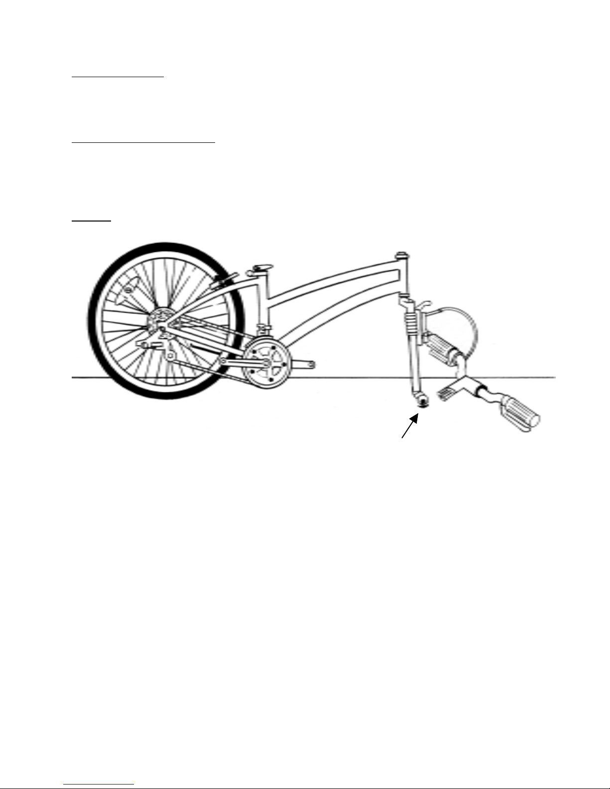
STEP 4: STAND FRAME UP
Carefully stand the bike up using the Fork ends as a stand. Make sure the Fork is facing forward
as per the drawing below.
FIG. 1
Fork Protective Spacer
( for shipping only )
3

STEP 5: CONNECTING HANDLEBAR
A) Remove the protective cardboard and rubber cap from the bottom of the Handlebar Stem Cone. (See FIG. 2).
B) Remove plastic plug on top of Stem Bolt. Before inserting the Stem into the Head Tube you may need to
loosen the Stem Bolt slightly 1-3 turns counter clockwise so the Stem Cone will fit into theHead Tube (See FIG. 2).
C) Now insert the Handlebar Stem into the Head Tube of the bicycle Frame so there is approximately
2 inches from the top of the Head Tube to the Handlebar T ilt Arm. (See FIG. 2 & 3). Do not raise the Stem
above Minimum Insertion Line. The approximate maximum Stem height is 3.75”. Firmly tighten clockwise the
Handlebar Stem Bolt with the large 6mm Allen Key . (See FIG. 2). Y ou will adjust the Handlebar later .
FIG. 2 FIG. 3
Stem Bolt Plug
2.0”
Handlebar Stem
Bolt (6mm)
3.75”
Minimum
Insertion Line
Stem Cone
Head Tube
See pages 14-16 for a more complete understanding of the Handlebar if necessary.
D) Before going any further, make sure the Brake and AutoMax cables are not tangled and Cables are
correctly engaged into Brake Handles. (See FIG. 4 & 5). Y ou will adjust the Handlebar later .
Remove
Cap
FIG. 4 FIG. 5
YES NO!
4

STEP 6: CONNECTING SEAT POST
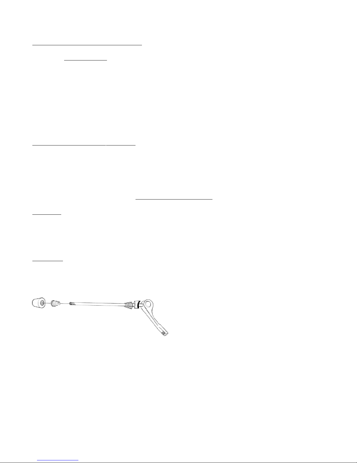
The action of the Quick Release Cam squeezes the Seat Collar around the Seat Post to hold the Seat Post
securely in place. The amount of clamping force is controlled by the T ension Adjusting Nut. T urning the
T ension Adjusting Nut clockwise while keeping the Quick Release Lever from rotating increases clamping
force; turning it counterclockwise while keeping the Lever from rotating decreases clamping force.
A) Release the Seat Post Quick Release on the Seat Tube by opening the Quick Release Lever . (See FIG. 8).
B) Insert the Seat Post into the Seat Tube and lower the Seat Post all the way (See FIG. 7). Y ou will adjust
seat height later. Do not raise the Seat Post above Minimum Insertion Line.
C) Keeping the Seat parallel with the Frame turn the T ension Adjusting Nut clockwise with one hand while
holding the Quick Release Lever with the other hand. Turn the T ension Adjusting Nut until it is as tight as you
can get it by hand. (See FIG. 8).
D) Now close the Quick Release Lever so that the Seat Post is secured in the Seat Tube. The full force of the
Quick Release Cam is required. Quick Release Lever should be turned towards Front Wheel. Check Rear
Reflector is straight and tight.
FIG. 6 FIG. 7
Rear
Reflector
Minimum
Insertion Line
FIG.
Tension Adjusting Nut
LOOSEN
TIGHTEN
Quick Release Lever
IMPORT ANT: If you can fully close the Quick Release and the Lever does not leave a clear imprint in the palm
of your hand, the tension is insufficient. Open the Lever; turn the T ension Adjusting Nut clockwise a quarter turn;
then try again. If the Lever cannot be pushed all the way to a closed position, return the Lever to the OPEN
position. Then turn the T ension Adjusting Nut counterclockwise one-quarter turn and try tightening the Lever
again.
8
CLOSED
OPEN
5
 Loading...