

Page 1
GUIDEBOOK TO ENJOYMENT OF
YOUR VENTURE RV
RECREATIONAL VEHICLE
Sonic
PDF created with pdfFactory trial version www.pdffactory.com
Page 2
THE PURPOSE OF THE VENTURE RV OWNER’S MANUAL
IS TO PROVIDE THE MOST CURRENT INFORMATION
AVAILABLE CONCERNING VENTURE RV RECREATIONAL
VEHICLES. OPERATION AND MINOR MAINTENANCE IS
THE MAIN FOCUS OF THIS BOOK.
MAINTENANCE OF YOUR RECREATIONAL VEHICLE IS
IMPORTANT TO KEEPING YOUR COACH IN GOOD
CONDITION. FAILING TO PROVIDE MAINTENANCE, AS
SUGGESTED, COULD RESULT IN LOSS OF WARRANTY
COVERAGE. REVIEW THE COPY OF YOUR VENTURE
RV TOWABLE TRANSFERABLE LIMITED WARRANTY,
WHICH HAS BEEN SUPPLIED TO YOU WITH YOUR
WARRANTY REGISTRATION FORM.
ADDITIONAL MANUALS MAY BE SUPPLIED AND
AVAILABLE BY THE MANUFACTURER OF THE
COMPONENT AND/OR APPLIANCE. SEE THE
INFORMATION PACKET IN YOUR COACH.
Conventional Travel Trailer
© 2018 VENTURE LITHO U.S.A.
PDF created with pdfFactory trial version www.pdffactory.com
9-2017
Page 3

We congratulate you on your purchase of a
VENTURE RV, recreational vehicle. You have
chosen a quality built RV which should provide you
with many years of camping memories and fun.
The recreational vehicle you have purchased has
been inspected by our trained inspectors and fully
meets our high quality standards.
As the owner of a new VENTURE RV, you can rest
assured that we will do all we can to keep you a
“happy camper”. Naturally, your selling dealership is
always happy to help you with any questions you
may have or service you may need. And should you
need assistance when traveling, with VENTURE RV
dealers nationwide, assistance is usually just
minutes away.
VENTURE RV
0985 N 900 W
Shipshewana, IN 46565
PDF created with pdfFactory trial version www.pdffactory.com
Page 4

TABLE OF CONTENTS
Chapter 1 – Introduction to RV Ownership ................................... 1
Safety Considerations ................................................................. 2
Reporting Safety Defects ...................................................... 2
Safety When Emergency Stopping ....................................... 3
Additional Safety Considerations .......................................... 3
Extended or Cold Weather Use .................................................. 4
Condensation .............................................................................. 4
Causes...….…………………………………………………..…4
Solutions…………………………………………………………5
Interior Ventilation……………………………………...……………6
Chapter 2 – Service Procedures..................................................... 7
Basic Service Procedures ........................................................... 7
Dealer... ................................................................................ 8
Factory…... ........................................................................... 8
Parts….. ................................................................................ 8
Owner’s Responsibility ......................................................... 8
Seasonal Site... ..................................................................... 9
Towable Limited Warranty……….. ............................................ 10
Chapter 3 – Using Your RV ........................................................... 14
Equipment…. ............................................................................. 14
Tow Vehicle ........................................................................ 14
Hitches – Travel Trailer ....................................................... 14
Hitch Height Specifications – Travel Trailer ........................ 15
Hook-Up (Travel Trailer) ..................................................... 15
The Safety Chain (Travel Trailer) ....................................... 16
Traveling…. ............................................................................... 17
Weights ............................................................................... 17
Weighing Vehicle (Loaded or Unloaded) ............................ 18
Loading the Trailer—Distribution ........................................ 18
Towing.. .............................................................................. 20
Tires…... ............................................................................. 20
Safety First-Basic Tire Maintenance ............................ 21
Understanding Tire Pressure and Load Limits ............. 22
Checking Tire Pressure ................................................ 22
Tire Size ....................................................................... 22
Tire Tread ..................................................................... 23
Tire Balance and Wheel Alignment .............................. 23
Tire Repair .................................................................... 23
Tire Fundamentals ....................................................... 23
Vehicle Load Limits ...................................................... 24
Cargo Capacities ................................................................ 24
How Overloading Affects Your RV and Tires ..................... 25
i
PDF created with pdfFactory trial version www.pdffactory.com
Page 5

How to Change a Tire ......................................................... 26
Wheel Bearings…………………………………….………….26
Wheel Lugs..…………………………………….…………….26
Brakes—Electrical .............................................................. 27
Breakaway Switch .............................................................. 27
Setting Up and Using Your Recreational Vehicle ............... 28
Travel Trailer Hook Up………………………………………..29
General Detector Information………………………………..30
Safety Detectors….………….…...………………...…………30
Fire Extinguisher………………………………………….30
Propane/ Carbon Monoxide Detector….…...……..…...31
What is Carbon Monoxide?..........................................31
Dual Sensor Technology………………...…………….. 31
Operation…….…………...…………………………….…31
Low Power Option...….……………………………..…...32
Visual and Audible Alarm Signals……….………...……32
CO Alarm….. ................................................................ 32
Propane Gas Alarm……………………………………...33
Malfunction/Service Signal………………………………33
End of Life Signal…………………………………………33
Smoke Alarm……....…...….……………………………..34
Operation…………………………...……………………..34
Testing……………………………………..………………34
Steps-Two or Three ............................................................ 35
Windows ............................................................................. 36
Doors….. ............................................................................. 36
TV Antennas (Standard Roof Mount) ................................. 36
Slide Outs……………………………………………………...38
Power For Operation...………………....………………..38
Trailer Set-Up Requirements-General……..………… .39
Below Floor Slide System…………...……………….….39
Above Floor Slide Out ………………………...……...…39
Electrical Components……………………………….…. 40
Manual Override…………...………………………….….…..41
Below Floor Slide Out…………………….……….……..41
Above Floor Slide Out……………..….…………….……41
Blinds………………………………………………….………..41
Chapter 4 – Systems ..................................................................... 43
Water and Drainage Plumbing .................................................. 43
Fresh Water System………………………………......…………..43
Tanks…….. ......................................................................... 43
Filling Fresh Water System ................................................. 43
12-Volt Demand Pump ....................................................... 44
Faucets…............................................................................ 45
ii
PDF created with pdfFactory trial version www.pdffactory.com
Page 6

Bath and Shower ................................................................ 45
Outside Shower (Optional) ................................................. 45
Fresh Water Lines…………………………………...………..46
Lo-Point Drains……………………………...……….………..46
Sanitizing and Filling the Potable Water System ................ 47
For Water Lines only……………………….….……...….47
Drainage (Fresh Water) ...................................................... 48
To Drain System….………………………..……………..48
Sanitation System ..................................................................... 48
Toilets…..……… ................................................................. 48
Using Toilet and Tank System…………....………..………. 49
Vents…….………………………………………………….…..49
Holding Tanks... .................................................................. 50
Draining the Tanks .............................................................. 50
Black Tank Flush System…………………………..………..51
Maintenance for Holding Tanks .......................................... 52
Winterizing Your Recreational Vehicle ............................... 52
By Pass Kit…………………………………………………….53
Propane Fuel System………. .................................................... 54
Propane Container……… ................................................... 54
Servicing and Filling Propane Containers .......................... 55
Installing Propane Containers……………………………… 56
Regulator………. ................................................................ 58
High Pressure Hoses with Acme Connectors ..................... 60
Main Supply Hose – Low Pressure .................................... 60
Operation……………………………………………………… 61
Checking for Leaks……………………………………………61
Propane Gas Consumption ................................................ 62
Electrical System……… ............................................................ 64
General Information ............................................................ 64
Changes and Modifications ................................................ 64
120 Volt AC System ............................................................ 64
Power Cord 30 Amp ……….. ....................................... 64
Circuit Breakers and Box ............................................. 65
GFCI Protection…………………………………………..66
12 Volt DC System ............................................................. 67
Converter………………………………………………….67
Auxiliary Battery .......................................................... 68
Circuit Breakers and Fuses-12Volt DC ........................ 68
Exterior Lights and Connector, 12V ............................. 70
Porch Lights………… ................................................... 70
Brake Wiring…….......................................................... 70
Chapter 5 – Appliances…………................................................... 72
Safety—-Read Before Operating………………………………72
Furnace………………................................................................ 73
iii
PDF created with pdfFactory trial version www.pdffactory.com
Page 7

Thermostat……………………………………………………...73
Operating Instructions………………………………………...74
External Vents…………………………………………………75
Ducting……………………………………………….…………75
Drop-In Cook Top Operation ..................................................... 76
Operating Instructions......................................................... 76
Water Heater…………. ........................................................ .....78
Operating Instructions: Gas………..……………….…...78
Operating Instructions: Direct Spark Ignition……….….78
Operating Instructions: Electric Element……………….79
To Turn Off Water Heater……………………………….81
Winterizing Your Water Heater………………………………81
Refrigerator………………………………………………………....81
Leveling…………… ........................................................... .81
Operation During Travel……………………………………...82
Venting………………………………………………………….82
Moisture Reduction Heater ................................................. 82
Door Sealing……… ............................................................ 82
Door Handles……….. ......................................................... 83
Refrigerator Storage………….. ........................................... 83
Operating the Refrigerator Controls……………………………..83
Air Conditioner……………………………………………………..84
Monitor Panel……………………………………………………....84
Important Phone Numbers………………………………….…….85
iv
PDF created with pdfFactory trial version www.pdffactory.com
Page 8

CHAPTER 1
INTRODUCTION TO RV OWNERSHIP
Welcome to the growing family of new VENTURE RV owners and the
world of recreational vehicle travel. The purchase of your VENTURE
RV product allows you to enter this type of camping and leisure
travel. Your coach has been designed and engineered to offer many
comforts of home. VENTURE Recreational Vehicles are designed
and constructed to be used as temporary living quarters for camping
and travel uses. The coaches are not intended for hauling cargo.
This owner’s manual was prepared to assist you in understanding the
proper use and operation of various containment systems, servicing
and maintenance of component parts, and explanation of your
warranty protection. If this is your first RV travel coach, you will want
to acquaint yourself with all aspects and information found in this
manual plus manuals supplied by component manufacturers.
These materials will reflect the most current information available for
the user. Some components and items may not be in your coach as
they may be options on different models.
Keep this owner’s manual in your recreational vehicle for handy
reference. Get to know your new vehicle and how it operates. You
should carefully read and understand these instructions, as well as
information supplied by the manufacturers of separately warranted
products, since they contain important operating, safety, and
maintenance instructions. If you have questions that are not
adequately answered by this manual or other booklets, consult your
dealer. If he cannot satisfactorily answer your questions, he will call
our staff for additional information.
Every effort has been made to provide you with a safe, dependable
product. Your vehicle complies with applicable requirements of
Federal Motor Vehicle Safety Standards, State Regulations,
Canadian Standards Associations (CSA) where applicable, and
complies with requirements of ANSI Standard 1192, the nationally
recognized “Standard for Recreational Vehicles – Installation of
Plumbing, Heating and Electrical Systems.” The Recreational Vehicle
Industry Association (RVIA) and Canadian Standards Association
(CSA) periodically inspect our production lines and assist us in
maintaining strict compliance with installation and safety standards for
those systems. Your follow-up with periodic safety inspections
and a program of preventive maintenance is important for the
continuation of safe and trouble-free operation.
1
PDF created with pdfFactory trial version www.pdffactory.com
Page 9

Camping is a great way to relax and enjoy the outdoors with your
friends and family. Please remember to tread lightly on our beautiful
land and leave only your footprints so that others may enjoy nature
as much as you did.
SAFETY CONSIDERATIONS______________________________
The terms NOTE, CAUTION, WARNING, and DANGER have
specific meanings in this manual as well as component manuals.
A NOTE provides additional information to make a step or procedure
easier or clearer. Disregarding a NOTE could cause inconvenience,
but would not be likely to cause damage or personal injury.
A CAUTION emphasizes areas where equipment damage could
result. Disregarding a CAUTION could cause permanent mechanical
damage. However, personal injury is unlikely.
A WARNING is giving notice to user that potential injuries may
occur to a person from equipment and mechanical failure.
Disregarding a Warning may result in serious physical injury to
occupant.
A DANGER alerts areas where safety measures MUST be strictly
adhered to, as such failures can be dangerous. Disregarding a
Danger could causing serious injury and possible loss of life.
Reporting Safety Defects
If you believe that your vehicle has a defect which could cause a
crash or could cause injury or death, you should immediately inform
the National Highway Traffic Safety Administration (NHTSA) in
addition to notifying VENTURE RV.
If NHTSA in addition receives similar complaints, it may open an
investigation, and if it finds that a safety defect exists in a group of
vehicles, it may order a recall and remedy campaign. However,
NHTSA cannot become involved in individual problems between
you, your dealer or VENTURE RV.
To contact NHTSA, you may either call the Auto Safety Hotline tollfree at 1-800-424-9393 or write to:
NHTSA
US Department of Transportation
Washington, DC 20590
2
PDF created with pdfFactory trial version www.pdffactory.com
Page 10

You can also obtain other information about motor vehicle safety
from the Hotline.
Safety When Emergency Stopping
It is wise to carry road flags and/or triangular warning devices to be
used when necessary. When pulling off a highway, use your four
way hazard lights as warning flashers, even if only to change
drivers. Pull off the road way completely if at all possible to change
flat tires or any other emergency needs.
Additional Safety Considerations
1. Sanitize the fresh water supply system periodically (see
sanitizing instructions).
2. Keep water connection fittings from coming in contact with the
ground or drain hose to reduce chance of contamination.
3. Enlist services of a Qualified RV Technician to fix propane or
electrical appliances, or any other gas or electrical system
problem.
4. Always have a serviceable fire extinguisher placed in an easily
accessible location.
5. Insure that tires are in good condition and properly inflated.
Watch tire inflation closely. Under-inflated tires will overheat.
Overheated tires are a potential hazard as they may throw
rubber and cause a blow-out. Check the tire pressure before
each trip while the tires are cold.
6. Check and tighten the wheel lugs regularly (every 50 miles when
new until 200 miles are reached and then check the lugs every
500 miles).
7. Check the brakes in a safe area – not while traveling on a busy
highway.
8. Always block the trailer wheels solidly before unhitching.
9. Before leaving a camp area with a trailer in tow, insure:
a. The safety pin or locking lever is seated.
b. The breakaway wire is attached to the tow vehicle.
c. All jacks are raised so that they cannot touch the ground.
d. The 110-volt electrical cord is properly stored.
PDF created with pdfFactory trial version www.pdffactory.com
3
Page 11

e. The safety chains are connected.
f. All interior lights are off.
10. Observe and obey the warning labels attached to your vehicle
concerning propane, water, electricity and loading.
11. Extinguish all campfires before leaving your campsite.
EXTENDED OR COLD WEATHER USE
Your VENTURE recreational vehicle has been built for enjoyment in
a recreational manner. This recreational vehicle is not intended to be
used as full-time living quarters. Nor is this a four season unit. Using
this unit in freezing conditions is not recommended. However, if unit
is used in freezing weather, following are guidelines to follow. Any
problems resulting from freezing are not covered under warranty.
1. For winter use in freezing conditions, more protection may be
required. Use skirting and/or insulation below floor level to
provide additional protection.
2. Remember, water freezes at 32o Fahrenheit whether fresh or
drainage. Proper care must be used to protect any system at 32
Fahrenheit or lower. Local recreational vehicle dealers and
campground personnel may be able to advise you on needed
protection.
3. Energy requirements, such as propane and electrical supplies
must be adequate. Protect your propane regulator from freezeups.
4. During cold weather you will experience more condensation than
normal. Using ventilation or a dehumidifier may be needed.
CONDENSATION_______________________________________
Where it comes from, what causes it, and various solutions.
Condensation is not a warranty issue.
Causes:
A. When cooking food or taking a shower, warm moist air circulates
throughout the coach attaching itself to cooler surfaces, forming
beads and running down wall or window
o
4
PDF created with pdfFactory trial version www.pdffactory.com
Page 12

B. Normal breathing will emit approximately 1/2 pint of moisture
into the air per person, per day. The more occupants the greater
quantity of condensation you may find.
Solutions:
1. When taking a shower, open bath roof vent approximately ½
inch allowing moisture to escape.
2. Use the power vent over range when cooking.
3. If condensation is found in cabinet or closets, open door slightly
to equalize temperature and provide ventilation.
4. Opening windows and roof vents, when possible, allowing warm
moist air to escape is the best way to reduce condensation.
5. Under extreme conditions, you may need to use a dehumidifier
to remove moist air conditions.
Uncontrolled condensation can cause dampness, mildew, etc.,
inside your recreational vehicle. Be sure to make strong efforts to
control condensation.
CAUTION
!
Continuous living in your recreational vehicle could cause accelerated wear
to components above recreational use.
5
PDF created with pdfFactory trial version www.pdffactory.com
Page 13

INTERIOR VENTILATION
A new coach always has a peculiar aroma in it due to all the
components used to build it, such as paneling, plywood, carpet and
fabrics.
Allowing fresh air to move and circulate throughout a new
recreational vehicle is very valuable for several reasons.
1. Components used to build RV’s always have a “new” smell to
them, possibly irritating the respiratory system of the human
body on warm days.
2. Fresh air is always good for the human body unless allergies
are a factor.
Numerous ways are provided to exchange air in coaches.
1. Open windows on non-rainy days, allowing air exchange
between inside and outside.
2. Power hood vent above cooking stove will send heat and food
smell outside.
3. Roof vent; numerous types;
a. Standard air flow using gravity flow method.
b. Power ( 12v or 110v ) vents will move air faster.
c. Hi-volume power vents, operation in 12 volt power can
exchange air in a coach in several minutes if windows
are open accordingly. If there is a fan in the rear, open
window (s) in front.
Different brands/models have different features, such as remote
control, rain sensor, variable speed control switch, etc.
Read carefully the operating instructions which are provided by the
manufacture and can be found in your coach.
6
PDF created with pdfFactory trial version www.pdffactory.com
Page 14

CHAPTER 2
SERVICE PROCEDURES
BASIC SERVICE PROCEDURES___________________________
VENTURE RV and Your VENTURE RV Dealer have a strong and
dedicated interest in maintaining the highest quality customer
relations with its owners. Your satisfaction with your VENTURE
recreational vehicle and your VENTURE RV dealer is our primary
concern. In addition to producing high quality products, we want to
assure our customers of our support with parts and service
availability. Our dealer network is the first choice to serve and supply
your needs for your recreational vehicle. Our authorized
dealers will pleasantly assist in providing service maintenance
needs plus parts, options, and information concerning your
recreational vehicle.
Should you experience a problem with service availability, please
follow the steps in the order listed below.
1. Contact your selling dealer’s service department for an
appointment. Describe to the best of your knowledge the nature
of the problem. Please keep appointments to establish a good,
workable relationship.
2. Contact the owner or general manager of the dealership should
the initial attempt fail with the service department.
3. Contact: Customer Relations Department
VENTURE RV
0985N 900W
Shipshewana, IN 46565
Phone: (888) 988 8440
Hours: (8am-5pm E.S.T.)
E-mail: [email protected]
Website: http://www.venture-rv.com
Give all the above information as requested along with the
serial number of the coach in question. We will make every
attempt to resolve your problem.
Please bear in mind that most problems arise from
misunderstandings concerning warranty coverage and service. In
most instances, you will be referred to the dealer level and your
concerns will be resolved with the dealer’s facilities and personnel.
7
PDF created with pdfFactory trial version www.pdffactory.com
Page 15

Dealer
Your authorized VENTURE RV dealer has performed a PDI (predelivery inspection) on your recreational vehicle. Since your dealer
is authorized to sell VENTURE RV products, they are also there to
supply parts, optional equipment, and provide service repairs,
warranty or otherwise as needed.
First choice for warranty repairs is your selling VENTURE RV
dealer. Other dealers can be used, however, prior approval is
required.
Some recreational vehicle dealers may be authorized service
centers for certain manufacturers of products warranted separately,
such as appliances. Check with your dealer before contacting
anyone else to reduce delays. If the dealer is not an authorized
service center for the product in question, he can assist you in
obtaining authorized service.
Factory
Service repairs can be performed at the manufacturing facility at
Shipshewana, Indiana. Should your VENTURE RV product be in
need of major repairs and your dealer recommends factory repairs,
please follow the steps listed below for such work.
1. Your dealer must make an appointment with service personnel
at the factory PRIOR to your arrival.
2. Any freight costs, are the responsibility of the owner as listed in
the warranty coverage schedule.
Parts
Stocking of parts varies from dealer to dealer. Any authorized dealer
can order any required part to be shipped to their dealership. All
parts are obtained through authorized VENTURE RV dealers only.
Owner’s Responsibility
When owning and using a recreational vehicle, it is important to
perform regular and normal maintenance. This is recommended
twice a year, spring and fall, to prevent undesired deterioration of
your coach. Weather elements play an important function on
sealants and other components requiring normal maintenance.
8
PDF created with pdfFactory trial version www.pdffactory.com
Page 16

As an owner and operator, it is your responsibility and obligation to
inspect and return your coach to an authorized dealer for repairs as
required. Your authorized selling dealer is always your first choice
and he certainly has continued interest in your satisfaction. As your
manufacturer, we recommend that inspection and service be
performed by your selling dealership.
If you are traveling and are unable to locate an authorized
VENTURE RV dealer, or an authorized dealer for the component
needing service, please call our customer service office at (888)988-
8440. Service at a non-authorized dealer MUST have prior
authorization. You may be asked to return any mechanical parts that
are replaced before reimbursement consideration is made.
Unauthorized or improper repairs may void the warranty of that
component. Always keep your owner’s manual along with a copy of
your warranty registration with you when traveling.
Seasonal Site
When placing your unit on a camp site in the spring and returning it
in the fall to your home, it’s classed as a “seasonal site.”
Performing repair work on such a site is not recommended for
numerous reasons; available parts, tools, space, weather conditions,
etc.
Any service repairs which require a service technician also require
the unit to be taken to a service facility, preferably your selling
dealer.
Warranty coverage does not include trip or service call costs for
such a trip. It is the owners responsibility to provide for such costs.
9
PDF created with pdfFactory trial version www.pdffactory.com
Page 17

KZRV, LP d/b/a VENTURE RV
TOWABLE LIMITED WARRANTY
One Year Limited Warranty
SUMMARY OF WARRANTY: Venture RV warrants that every towable
recreational vehicle or truck camper purchased from an authorized Venture RV
dealer to the first retail consumer was free from substantial defects in materials
and workmanship when it arrived on the dealer’s lot, except those exclusions set
forth below. Nothing contained herein shall be interpreted as a promise of future performance. The warranty period begins on the date of purchase or the
date the unit is first placed in service, whichever is earlier. This Towable Limited Warranty [“TLW”] does not apply to towable recreational vehicles or truck
campers purchased from any source other than an authorized Venture RV dealer.
EXCLUSIONS FROM WARRANTY: Excluded from coverage under the
TLW are: (1) items added, changed, or modified after the unit left the possession of Venture RV; (2) units used for any commercial purpose; (3) units used
for full-time residential use or more than occasional recreational use ; (4) wear
and tear caused by normal usage by the consumer, including but not limited to
fading or discoloration of soft goods [e.g., tents, upholstery, drapes, carpet, vinyl, screens, cushions, and mattresses], fading or discoloration of exterior or
fiberglass components, tears, punctures, soiling, mildew, mold, and the effects
of moisture condensation inside the unit; (5) the effects of alteration, tampering,
mishandling, neglect, abuse, misuse, weather, acts of nature, acts of God, or
corrosive atmospheres that promote rusting, oxidation, or pitting; (6) minor imperfections that do not interfere or affect the suitability of the unit for its intended use; (7) the effects of consumer’s or transferee’s failure to perform normal
and routine maintenance [e.g., inspections, lubrication, adjustments, tightening
of screws and bolts, tightening of lug nuts and wheels, sealing, rotating, cleaning, or other damages resulting from failing to follow the maintenance schedule
and procedures in the owners manual; (8) damages resulting from misalignment
or adjustments to axles or spindles caused by improper maintenance, modification, loading, unloading, road hazards, road defects, off road travel, or tire failures; (9) damages caused by the negligent or intentional use or misuse of the
unit by the consumer or transferee, including but not limited to occurrences
while towing the unit; (10) loss or damage caused by a person or business as a
result of transporting the unit after sale to the consumer, delivering the unit, or
parking the unit; (11) loss or damage to the plumbing system caused by freezing; (12) claims for personal injuries of any type; (13) costs of transportation of
the unit for repairs; and (14) components that are warranted separately by another manufacturer [the warranty provided by a component manufacturer is the
sole responsibility of that manufacturer, and Venture RV does not warrant those
components. Please refer to the warranties issued by the component manufacturers for the terms and conditions of such warranties].
10
PDF created with pdfFactory trial version www.pdffactory.com
Page 18

TO OBTAIN WARRANTY SERVICE: Warranty service may be performed only at Venture RV, or at Venture RV authorized dealers and service
centers. Contact Venture RV for a list of authorized dealers and service centers. REPAIRS OR REPLACEMENTS BY UNAUTHORIZED DEALERS
OR SERVICE CENTERS WILL VOID THIS TLW. If the consumer believes
that a claimed defect is covered by this TLW, contact must be made with
VENTURE RV, as described below, or an authorized Venture RV dealer,
WITHIN THE WARRANTY PERIOD. Sufficient information must be given
to attempt to resolve the claimed problem. Should Venture RV determine that
repair or replacement is appropriate, the consumer must deliver the unit to the
dealer or service center as directed. Delivery shall occur no later than thirty
(30) days after the authorization for repair or replacement. Do not deliver your
unit to Venture RV, an authorized dealer, or service center without prior authorization. All costs incurred by the consumer for transportation for warranty
service shall be the sole responsibility of the consumer. The consumer must
contact Venture RV by CERTIFIED MAIL with a written description of the
claimed warranted defect and the efforts to remedy it. FAILURE TO SO NOTIFY Venture RV IN THIS REGARD SHALL RENDER THIS TLW VOID
AS TO THE CLAIMED DEFECT. The scheduling of warranty work at an
authorized dealer or service center is not controlled by Venture RV and delays
may be experienced. Venture RV is not responsible for loss of use of the unit,
expenses for fuel, telephone, food, lodging, travel, loss of income or revenue,
or loss of or damage to personal property.
DISCLAIMER AND LIMITATIONS OF WARRANTIES: NEITHER
VENTURE RV, NOR ITS DEALERS SHALL BE LIABLE FOR INCIDENTAL,
CONSEQUENTIAL, INDIRECT, SPECIAL, OR PUNITIVE DAMAGES OF ANY
KIND OR ANY OTHER FINANCIAL LOSS ARISING OUT OF OR IN CONNECTION WITH THE SALE OR USE OF THIS PRODUCT, WHETHER BASED IN
CONTRACT, TORT, STRICT LIABILITY, EQUITY, OR ANY OTHER THEORY,
EVEN IF Venture RV HAS BEEN ADVISED OF THE POSSIBILITY OF SUCH
DAMAGES. Venture RV’S ENTIRE LIABILITY SHALL BE LIMITED TO REPAIR
OR REPLACEMENT, AT Venture RV'S SOLE OPTION.
THE UNITED NATIONS CONVENTION ON CONTRACTS FOR THE INTERNATIONAL SALE OF GOODS IS HEREBY EXCLUDED IN ITS ENTIRETY FROM
APPLICATION TO THIS TLW.
THIS TLW, AND THE REMEDIES HEREUNDER, ARE EXCLUSIVE AND IN
LIEU OF ALL OTHER WARRANTIES, EXPRESS OR IMPLIED, INCLUDING
WARRANTIES OF MERCHANTABILITY, FITNESS FOR A PARTICULAR PURPOSE, CORRESPONDENCE WITH DESCRIPTION, AND NON-INFRINGEMENT,
ALL OF WHICH ARE EXPRESSLY DISCLAIMED BY Venture RV. THIS TLW
GIVES YOU SPECIFIC LEGAL RIGHTS AND YOU MAY ALSO HAVE OTHER
RIGHTS THAT VARY DEPENDING ON LOCAL LAW. SOME STATES LIMIT
OR PROHIBIT LIMITATIONS OF WARRANTIES, SO THE ABOVE MAY NOT
APPLY TO YOU. YOU SHOULD CONSULT A COMPETENT ATTORNEY FOR
LEGAL ADVICE
11
PDF created with pdfFactory trial version www.pdffactory.com
Page 19

MISCELLANEOUS: No repair or replacement effected shall cause any
extension or renewal of the warranty period. Venture RV may make parts and/
or design changes from time to time without notice and repairs or replacements
may be made with new or different parts. Venture RV reserves the right to
make changes in the design or material of its products without incurring any
obligation to incorporate such changes in any product previously manufactured. At Venture RV’s, sole option, any dispute concerning any warranted
defect may be resolved through mediation or arbitration. This TLW shall be
governed by the laws of the State of Indiana, and any legal action shall be
brought only in the Circuit or Superior Court of LaGrange County, Indiana. In
case of conflicts between this TLW and any other warranties issued or conveyed by Venture RV, the terms of this TLW shall govern.
ALTERNATIVE DISPUTE RESOLUTION: The parties shall attempt in
good faith to resolve any disputes by negotiations. If unsuccessful ,Venture
RV may, in its sole discretion, elect to submit the matter to binding arbitration
and, if such election is exercised, the consumer covenants and agrees that he,
she, they, or it shall submit any such disputes to such binding arbitration. The
arbitral body shall be either the American Arbitration Association or the National Arbitration Foundation, and the rules of the body chosen by Venture RV
shall govern except to the extent same are in conflict with the Indiana Uniform
Arbitration Act, which shall govern. The arbitrator is expressly empowered to
enter an award of default against any party in the event of: (a) the failure or
refusal of such party to comply with any deadline fixed by the arbitrator; (b)
the failure or refusal of such party to make timely payment of any fees, expenses, or other charges billed by the arbitrator; or (c) any other failure or refusal
by such party to cooperate and participate in any aspect of the arbitration proceedings. The arbitrator will admit only relevant and reliable evidence at the
hearing, but no particular rules of evidence are specified for use. The hearing
shall be electronically recorded by an Indiana Notary Public or other officer
authorized by Indiana law to administer oaths, and all witnesses who shall testify shall be sworn on oath to tell the truth. The arbitrator may award injunctive relief, interest, and attorney fees in an equitable amount based upon the
degree to which the prevailing party prevails on the merits; however, the arbitrator is not empowered to award punitive or exemplary damages. All costs of
the arbitration, including the recording thereof, shall be shared equally by the
parties. The arbitration proceedings and award shall remain confidential, and
no party may disclose to any person, except attorneys for the parties, any aspect of the proceedings.
12
PDF created with pdfFactory trial version www.pdffactory.com
Page 20

WARRANTY REGISTRATION AND CONTACT INFORMATION:
The warranty registrations for component parts should be completed and delivered in accordance with the instructions contained therein. The TLW registration must be completed and returned to Venture RV within fifteen (15) days of
delivery of the unit to the consumer. Failure to do so can void this TLW or
cause delays in obtaining benefits. The TLW registration, and all inquiries,
must be directed to: VENTURE RV, Warranty Department, 0985N 900W,
Shipshewana, Indiana 46565, Telephone: (260) 768-4016. [Form 1 year 6-112]
Model Number____________ V.I.N.____________________________
Dealer Information:
[ ]
Customer Information:
Name: ______________________________
Address: ______________________________
______________________________
Phone: ______________________________
I HEREBY ACKNOWLEDGE THAT I HAVE RECEIVED,
READ, AND UNDERSTAND THIS TOWABLE LIMITED
WARRANTY, AND THAT I HAVE INSPECTED THE UNIT
AND FIND IT IN THE CONDITION REPRESENTED.
Date: ____________________
_______________________________
Purchaser
13
PDF created with pdfFactory trial version www.pdffactory.com
Page 21

CHAPTER 3
USING YOUR RV
In this chapter you will find three areas of useful information to assist you
with correct equipment, traveling, and finally, actually using your
recreational vehicle.
EQUIPMENT______________________________________
Tow Vehicle
Begin your camping experiences by obtaining a tow vehicle which will
adequately transport your recreational vehicle to and from your chosen
destinations. Your most important measuring tool is the GVWR, Gross
Vehicle Weight Rating, to cross match the capability of your selected tow
vehicle.
Most auto and truck manufactures provide trailer towing guides for their
products. Ask your local automotive dealer for a copy or call the factory’s
direct lines for information. Many tow vehicles, including mini-vans, have
special towing package options available for small travel trailers. Tow
vehicles with long wheel bases perform better than those with short
wheel bases.
A second factor is GCWR, Gross Combined Weight Rating, which refers
to the total weight of the tow vehicle and any vehicle in tow as a
“combined” weight. This information, supplied by the tow vehicle
manufacturer, is related to the capability of the tow vehicle.
The condition of the suspension in your tow vehicle is also an important
factor. Make sure your tow vehicle is in good operating condition and
follow the factory recommended maintenance guidelines.
Hitches – Travel Trailer
After obtaining your tow vehicle, it is very important to choose, and have
installed, a correct hitch system with weight distributing bars to
accommodate your coach if so required. This selection and installation
should be done by a professional hitch service center, which may or may
not be your selling dealer.
Weight distributing hitches apply leverage between the tow vehicle and
trailer. This assists in equalizing the weight between vehicles, resulting
14
PDF created with pdfFactory trial version www.pdffactory.com
Page 22
in both vehicles traveling level. The condition of the tow vehicle’s
suspension system will affect the towing performance capability of your
equipment.
Sway controls may be needed based on size and weight of coach, plus
capability of your tow vehicle.
CAUTION
!
Trailers with tandem axles need to travel as level as possible, avoiding
different weights on each axle plus handling conditions.
CAUTION
!
Using an oversized or undersized hitch can cause damage to the frame of
your travel trailer or tow vehicle.
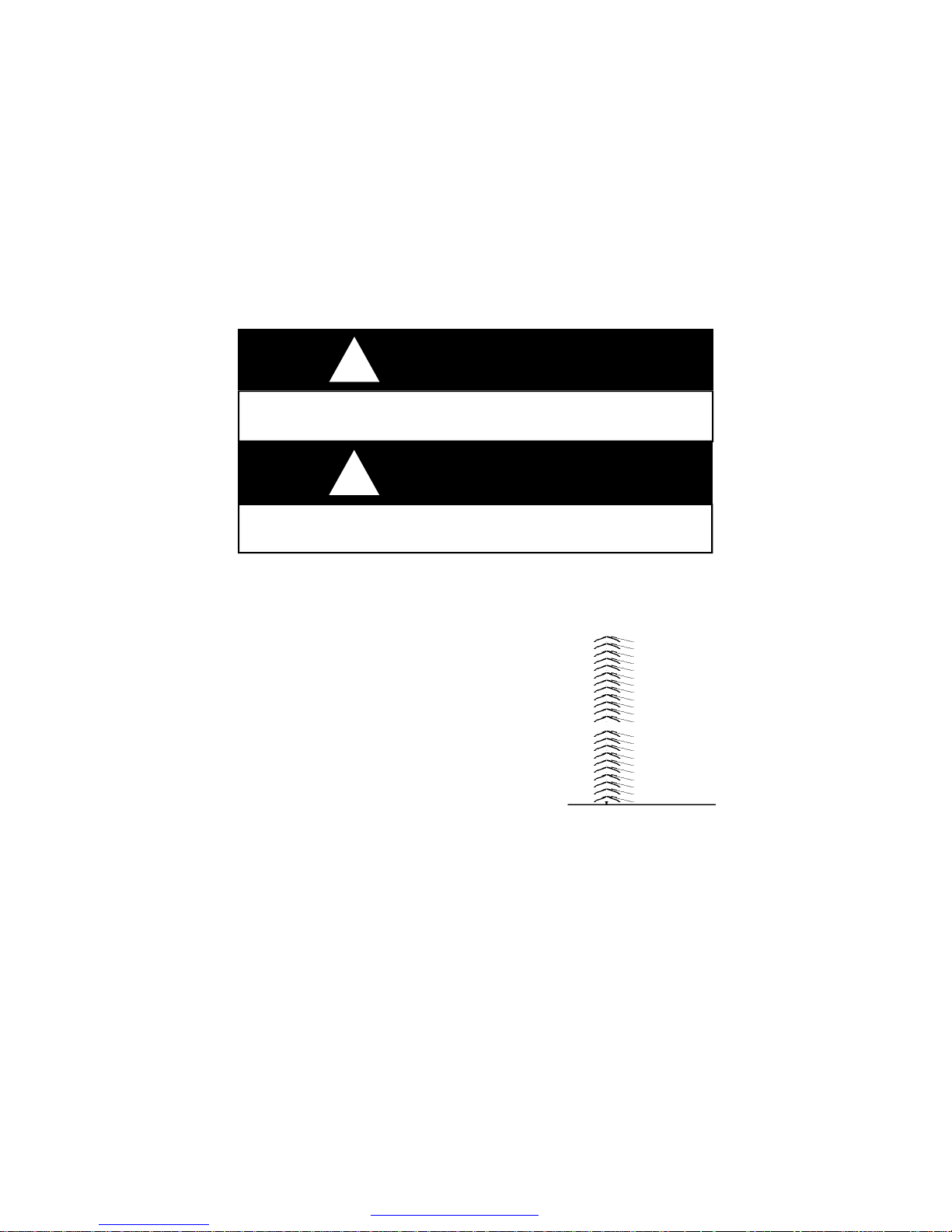
Hitch Height Specifications – Travel Trailer
Due to axles being either straight or drop bars,
the ball height will vary. To find the correct
height for the ball hitch, set your trailer on a flat
AND LEVELM surface in level position. Measure
from the inside of the ball socket to the ground,
approximately 18 to 22 inches as shown, for
correct spacing. You may wish to add 1 to 2
inches. to this amount to compensate for sag of
suspension of the tow vehicles when hooked to
tow vehicles.
Hook-Up (Travel Trailer)
Hooking up your travel trailer is not difficult and gets easier with practice.
The following procedure will help you until you become more
experienced.
1. To raise the tongue of trailer above the hitch ball on hitch, turn the
crank on the jack.
2. Open the coupler latch.
15
PDF created with pdfFactory trial version www.pdffactory.com
Page 23

3. Back the tow vehicle into proper position, coupler over ball.
4. Turn the crank on the jack to lower the coupler onto the ball hitch.
5. Close the coupler latch after completely seated and insert pin.
6. Install weight distributing bars (equalizer), when required, as
recommended by hitch supplier.
7. Retract the tongue jack to its maximum height.
8. Attach the cable for the breakaway switch to the tow vehicle.
9. Attach safety chains as per your state laws.
10. Plug in your 12-volt, seven way electrical connector from the tow
vehicle to the trailer connector.
11. Below are listed numerous items that should be inspected and tested
before traveling:
q All lights working on outside of coach.
q Stabilizer jacks in retracted position.
q Steps in retracted position.
q Refrigerator door latched completely.
q Loose items in secure position.
q Test brakes for operation before entering roadway.
The Safety Chain (Travel Trailer)
Safety chain requirements will vary from state to state. The chain
supplied with your coach meets SAE requirements for maximum gross
trailer weight.
1. Cross the left chain under the coupler and attach to the to the right
ring on hitch receiver.
2. Now take the right chain under coupler and attach to the left ring on
hitch receiver.
CAUTION
!
Remember – always have the safety chain attached to tow vehicle, as
required in your state.
16
PDF created with pdfFactory trial version www.pdffactory.com
Page 24

TRAVELING______________________________________
Weights
For safety reasons and federal regulations VENTURE RV provides
accurate weight specifications to owners. On the exterior left front corner
of the coach you will find the Federal “Vehicle Identification Number”
sticker, as required by the federal government. This tag supplies
information concerning your coach, such as: VIN number, date/month of
manufacture, tire size rating, plus information about weights as described
below.
—————————————————————————————
MANUFACTURED/FABRIQE KZRV. DATE
GVWR/PNBV; SHIPSHEWANA,IN.
GAWR/PNBE;
WHEEL/JANTE;
COLD INFL. PRESS./ PRESS DE GCNFL. A FROID
THIS VEHICLE CONFORMS TO ALL APPLICABLE U.S. FEDERAL
MOTOR VEHICLE SAFETY STANDARDS IN EFFECT ON THE DATE OF
MANUFACTURE SHOWN ABOVE.
VIN/NIV NUMBER.
—————————————————————————————
Gross Axle Weight Rating (GAWR): is the value specified as the load
carrying capacity of a single axle system, as measured at the tire-ground
interfaces. One of five components will determine this rating: tires, axle,
springs, brakes, or wheels. One of these five is generally rated slightly
less than the others which is used for the rating.
Gross Vehicle Weight Rating (GVWR): is the maximum permissible weight
of this trailer when fully loaded. It includes all weight at the trailer axle (s)
and tongue. This includes ALL cargo, options and liquids.
Unloaded Vehicle Weight (UVW): is the weight of this trailer as
manufactured at the factory. It includes all weight at the trailer axle(s) and
tongue. If applicable, it also includes full generator fluids, including fuel,
engine oil and coolants.
Cargo Carrying Capacity (CCC): is equal to the GVWR minus each of the
following: UVW, full fresh (potable) water weight (including water heater,
and full propane weight.
17
PDF created with pdfFactory trial version www.pdffactory.com
Page 25

Weighing Vehicle (Loaded or Unloaded)
The proper method to weigh the coach is to use a truck scale. Place the
coach axles (tires) and tongue jack, 12” to 24” from the edge. Unhook the
tow vehicle and move forward 6” to 8”. Now record total weight. Re-hook
the tow vehicle. Be sure no part of tow vehicle is on the scale. Now
record the axle weight only. The difference between the two weights is
the hitch weight.
VENTURE RV suggests you also weigh each side (2 tires) separate to
find balance of pounds per side. Its possible to have 1 side correct and
the other side over-loaded. Often the slide out side or refrigerator side will
be slightly heavier than the other.
The second sticker is about the weight of cargo placed in your coach.
Location is on the inside of your coach, on the screen door, or inside of a
cabinet door. It provides listed total allowable weight of cargo minus
liquids allowed, water and propane.
———————————————————————————
RECREATIONAL VEHICLE TRAILER CARGO
VIN——————————————
The weight of cargo should never exceed
Kg.—————————————— Lbs.
CAUTION
A load of water equals—————-kg, or ———-lbs. of cargo @
Kg or 8.3 lbs. per gallon.
——————————————————————————
Loading the Trailer—Distribution
Your recreational vehicle has been engineered to make maximum use of
the available space for living and storage areas. The equipment and
supplies you take along while traveling can be carried safely, provided the
additional weight is distributed properly. Proper weight distribution within
your trailer is an important factor in safety and efficiency of your trailer
brakes, hitching, and how your tow vehicle will pull the trailer. DO NOT
put excess weight in the rear only. Excessive weight in the rear area
tends to develop sway and “fishtailing” of the trailer.
Lightweight and bulky items such as paper products, bedding, clothing,
etc., should be stored in overhead cabinets and closets. Heavy items
18
PDF created with pdfFactory trial version www.pdffactory.com
Page 26

such as cooking utensils should be placed in lower cabinets. Canned
goods need to be in a pantry, if so equipped, or in lower cabinets. Also,
heavy items should be secured to avoid shifting during travel.
A reasonable principle in loading your coach is for every two pounds of
weight loaded in front of the axle, one pound of weight must be loaded
behind the axle. Also remember, improper side-to-side loading affects
spring condition.
Excess weight behind the axle lightens the hitch weight and will tend to
magnify any sway that may occur when passing trucks or when gusty
winds are present. Uncalculated weight can and will effect road
performance.
When using a weight distributing hitch and equalizer bars, you may
move/transfer hitch weight from coach to tow vehicle assisting with level
towing and easier travel.
CAUTION
!
DO NOT overload your unit. Please follow the GVWR when loading your
Venture recreational vehicle to avoid damages.
CAUTION
!
Any damage caused by improper loading or installing additional equipment
is NOT covered by Venture RV Limited Warranty.
Below is a blank space for you to calculate the “ Cargo Carry Capacity “
of your unit. You will find the weights of your unit on a sticker, placed on
the edge OR CENTER of the screen door. This will enable you to
determine your “ Cargo Carry Capacity “ in the different areas of your
unit.
19
PDF created with pdfFactory trial version www.pdffactory.com
Page 27

WARNING
!
The rear bumper on the frame will only carry 100lbs, therefore only the
spare tire carrier, and spare tire can be added to the bumper. Do not add
any other components to the bumper, such as bike racks, generators,
cargo containers, and etc. Such items could cause fatigue and weld stress,
which is not covered under warranty. Any such failures could damage your
property and endanger vehicles following your camper during travel, which
could result in an accident.
This frame is NOT designed or built to tow any trailer.
Towing
When towing your trailer you need to recognize the extra weight behind
your vehicle. Below is a list of things which you need to remember while
traveling.
1. With the trailer attached you will have slower acceleration and will
require more distance to stop.
2. Be sure you have enough area at corners when turning, as wider
turns are necessary. Be sure to use your turn signals for your own
safety and the safety of others.
3. In passing or changing lanes remember you will need a longer
distance to pass.
4. Use your rearview mirrors frequently to observe your trailer and traffic
conditions.
5. When being passed by a large truck or bus, be prepared for displaced
air as it may cause you to sway slightly, especially travel trailers.
6. When climbing steep, long grades and again while descending, user
lower gears even before it seems necessary. Use your brakes
smoothly and evenly.
7. Remember to drive more slowly on wet and icy highways to keep
control of your vehicle.
Tires
All VENTURE RV towable coaches are equipped with appropriate tires for
recreational vehicles. Tires are rated to carry weight as listed to G.V.W.R.
20
PDF created with pdfFactory trial version www.pdffactory.com
Page 28

PNEUS A FROID
Tires are radial in design using components to offer excellent strength and
mileage in all kinds of weather conditions.
Tires on your vehicle( s) are one of the most important components of the
towing package. Without inflated tires ,you will not be moving anywhere.,
Taking care of your tires during travel is very important. Top of the list is
maintaining correct air pressure and secondly is NOT over loading your
RV.
With proper care, the performance of fuel economy and handling on the
road will be better.
Safety on the road is very important in avoiding road hazards which can
damage your tires plus obeying the speed limit.
On the left front, exterior corner of your coach, you will find the (VIN) label
along with a placard as shown below, supplying information on tires such
as tire size and amount of air pressure (maximum).
Both placards and certification labels are permanently attached to the
trailer on the left front corner of exterior and easily readable from the
outside of the vehicle without moving any covers.
Due to weather elements, labels may fade over time. You may wish to
record this information and keep it on the inside of coach, perhaps with
owner’s manual.
——————————————————————————————TIRE . SIZE …... COLD TIRE PRESSURE
PNUE DIMENSIONS ………..PRESSIONDES
FRONT
AVANT
REAR
ARRIERE
SPARE
DESESCOURS
——————————————————————————————-
Safety First-Basic Tire Maintenance
Properly maintained tires improve the steering, stopping, traction, and
load carrying capability of your vehicle. Under inflated tires and
overloaded vehicles are a major cause of tire failure.
21
PDF created with pdfFactory trial version www.pdffactory.com
Page 29

CAUTION
!
It is recommended that the tire pressure be checked at the beginning of
each journey, and at least once per week during useage to obtain the
maximum life of the tires.
Understanding Tire Pressure and Load Limits
Tire inflation pressure is the level of air in the tire that provides it with loadcarrying capacity and affects the overall performance of the vehicle. The
tire inflation pressure is a number that indicates the amount of air
pressure as measured in pounds per square inch (psi) - a tire requires to
be properly inflated. (You will also find this number on the vehicle
information placard expressed in kilopascals (kPa), which is the metric
measure used internationally.)
The listed amount of air pressure is for maximum load capacity. When
traveling with less then full weight, you may wish to reduce air pressure
slightly for smoother ride.
While driving your tires will get warmer, causing air pressure to raise. To
get an accurate pressure reading, you must allow tries to cool for at least
3 hours.
For convenience, purchase a good quality pressure gauge to keep In
your tow vehicle. Gauges can be purchased at auto parts store.
Because tires are designed to be used on more than one type of vehicle,
tire manufacturers list the “maximum permissible inflation pressure” on the
tire sidewall. This number is the greatest amount of air pressure that
should ever be put in the tire under normal driving conditions.
Tire Size
To maintain tire safety, purchase replacement tires that are the same
size as the vehicle’s original tires or another size recommended by the
manufacturer. Look at the tire information placards, or the sidewall of the
tire you are replacing to find this information. If you have any doubt about
the correct size to choose, consult with the tire dealer.
22
PDF created with pdfFactory trial version www.pdffactory.com
Page 30

Tire Tread
The tire tread provides the gripping action and traction that prevent your
vehicle from slipping or sliding, especially when the road is wet or icy. In
general, tires are not safe and should be replaced when the tread is worn
down to 1/16 of an inch. Tires have built-in tread wear indicators that let
you know when it is time to replace your tires. These indicators are
raised sections spaced intermittently in the bottom of the tread grooves.
When they appear “even” with the outside of the tread, it is time to
replace your tires.
Tire Balance and Wheel Alignment
Tires are not balanced on your unit, nor is it required. You may choose to
balance the tires on your unit, however this will not be covered under
warranty.
Wheel alignments may be needed periodically due to road hazards,
such as pot holes, etc. This also is not covered under warranty, due to
being a uncontrollable element. Wheel alignments, will assist with getting
the maximum life from your tires. Alignments require special equipment,
and should be performed by a qualified technician.
Tire Repair
The proper repair of a punctured tire requires a plug for the hole and a
patch for the area inside the tire that surrounds the puncture hole.
Punctures through the tread can be repaired if they are not too large, but
punctures to the sidewall should not be repaired. Tires must be removed
from the rim to be properly inspected before being plugged and patched.
Tire Fundamentals
Federal law requires tire manufacturers to place standardized information
on the sidewall of all tires. This information identifies and describes the
fundamental characteristics of the tire and also provides a tire
identification number for safety standard certification and in case of a
recall.
Considerable quantity of information is built in to the side wall of a tire,
such as, date of manufacture, size, weight limit tire can carry, air
pressure, serial number, and where it was built.
23
PDF created with pdfFactory trial version www.pdffactory.com
Page 31

The letters “ST’ refer as “service trailer” meaning they are for RV
TRAILERS, manufactured for that purpose. These tires should not be
used for automotive use.
NOTE; Each original tire installed on KZ –RV recreational vehicles have a
speed rating of 75 mph, or greater. Please note maximum load rating, tire
pressure, and speed rating as imprinted on the sidewall of tire.
Effective in 2017 model year, your tires will have NITROGEN in them
instead of air. Green caps on the valve stems indicate contents as
nitrogen. Air may be used if nitrogen is not available.
Vehicle Load Limits
Determining the load limits of a vehicle includes more than understanding
the load limits of the tires alone.
On a trailer, there is a Federal certification label that is located on the
forward half of the left (road) side of the unit, called ‘VIN’, which is the
vehicle identification number.
The certification label will indicate the vehicle’s gross vehicle weight rating
(GVWR). This is the most weight the fully loaded vehicle can weigh. It
will also provide the gross axle weight rating (GAWR). This is the most
weight a particular axle can carry. If there are multiple axles, the GAWR
of each axle will be provided.
In the same location as the certification label described previous, there is
a vehicle placard. This placard provides tire and loading information. In
addition, this placard will show a statement regarding maximum cargo
capacity.
Cargo Capacities
Cargo can be added to the vehicle, up to the maximum weight specified
on the placard. The combined weight of the cargo is provided as a single
number. In any case, remember: the total weight of a fully loaded vehicle
can not exceed the stated GVWR.
Water and propane also need to be considered. The weight of fully filled
propane containers is considered part of the weight of the RV before it is
loaded with cargo and is not considered part of the disposable cargo load.
Water however, is a cargo weight and is treated as such. If there is a
24
PDF created with pdfFactory trial version www.pdffactory.com
Page 32

fresh water storage tank of 100 gallons, this tank when filled would weigh
about 800 pounds. If more cargo is being transported, water can be offloaded to keep the total amount of cargo added to the vehicle within the
limits of the GVWR so as not to overload the vehicle. Understanding this
flexibility will allow you, the owner, to make choices that fit your travel and
camping needs.
When loading your cargo, be sure it is distributed evenly to prevent
overloading front to back and side to side. Heavy items should be placed
low and as close to the axle positions as reasonable. Too many items on
one side may overload a tire. The best way to know the actual weight of
the vehicle is to weigh it at a public scale. Talk to your RV dealer to
discuss the weighing methods needed to capture the various weights
related to the RV. This would include weights for the following: axles,
wheels, hitch, and total weight.
How Overloading Affects Your RV and Tires
The results of overloading can have serious consequences for passenger
safety. Too much weight on your vehicle’s suspension system can cause
spring, shock absorber, or brake failure, handling or steering problems,
irregular tire wear, tire failure or other damage.
An overloaded vehicle is hard to drive and hard to stop. In cases of
serious overloading, brakes can fail completely, particularly on steep hills.
The load a tire will carry safely is a combination of the size of tire, its load
range, and corresponding inflation pressure.
Excessive loads and/or under inflation cause tire overloading and, as a
result, abnormal tire flexing occurs. This situation can generate an
excessive amount of heat within the tire. Excessive heat may lead to tire
failure.
It is the air pressure that enables a tire to support the load, so proper
inflation is critical. Since RVs can be configured and loaded in many ways,
air pressures must be determined from actual loads (determined by
weighing) and taken from the load and inflation tables provided by the tire
manufacturer. These air pressures may differ from those found on the
certification label. However, they should never exceed the tire limitation
for load or air pressure. If you discover that your tires cannot support the
actual weights, the load will need to be lightened.
Note: Tires are warranted by the manufacturer of their respective
brand and are to be serviced and warranted by a service center. Contact
your dealer for information on service centers for tires.
25
PDF created with pdfFactory trial version www.pdffactory.com
Page 33

How to Change a Tire
1. Place blocking under main rail/frame with hydraulic jack on top of
blocking in front of spring hanger, ALWAYS on main rail.
2. Break lug nuts loose before raising coach. DO NOT remove nuts.
3. Raise coach with jack until tire is off the ground.
4. Place additional blocking under frame for security support. DO
NOT depend fully on jack.
5. Be sure coach is solid and will not move with tire and wheel off.
6. Remove lug nuts when tire is off the ground.
7. Install spare tire and wheel onto hub.
8. Reinstall lug nuts and tighten firmly.
9. Drop tire and wheel onto ground after removing supports.
10. Now fully tighten and torque lugs at 90 to 120 foot pounds.
11. Place all equipment into coach or tow vehicle, blocking and jack.
12. Re-torque wheel after traveling 100 miles.
Wheel Bearings
ALL wheel bearings are pre-lubricated during assembly of axle and
brakes. Your coach may have ‘ULTRA LUBE’ method of having a grease
fitting in the end of axle. Remove rubber cap on end and use standard
grease gun to place 6 TO 8 shots of grease into bearings. Don’t forget to
repack your bearings correctly as per maintenance manual.
Wheel Lugs
When the wheels are installed on your recreational vehicle, the lug nuts
must be tightened at 90-120 foot pounds of torque. Powder coat painted
wheels may require more torque attempts due to thickness of paint. You
must re-torque the wheel lugs at 50 and 200 miles when new. A decal
on the wheel may require torque earlier.
After your first trip, check the wheel lugs periodically for safety. The
wheel lugs should then be checked after winter storage, before starting a
trip or following extensive braking. The size of bolts or nuts is 13/16 inch
standard and 3/4” for chrome nut. Over torque will damage components,
especially if torque wheel lugs goes over 150 pounds. Normally the
“nut” fails first however the embossing on the wheel can also be
flattened, and then fail to keep wheel tight.
26
PDF created with pdfFactory trial version www.pdffactory.com
Page 34

Brakes – Electrical
Electric brakes on your recreational vehicle are designed to work in
conjunction with the hydraulic brakes on your tow vehicle. This means to
have the best brake performance on both systems, the trailer and the tow
vehicle must perform and operate together. Any attempt to use either
brake system alone, tow vehicle or trailer will cause accelerated wear and
damage.
A brake control is required to be installed under dash of tow vehicle to
operate brake system, using 12 volt DC power. Electronic type is used
most widely. Each brand has their own operating instructions.
Battery in the tow vehicle is your primary source of power to operate the
brake system in towable trailer. Keep battery and charging system in
good working condition to ensure available energy when needed.
Wiring to operate your brakes must be sized correctly in both vehicles,
suggesting a minimum of 14 gauge from tow vehicle to trailer brake
assemblies. Wiring is done parallel, never in series. Being parallel, there
will be equal voltage at each brake assembly for equal braking capability
and performance.
Use the foot pedal control for general operation on combined use of both
brake systems. Manual control is to be used only in special situations,
such as slow movement or icy road conditions. In open position,
electrical current will flow to brake assemblies activating them.
When applying brakes to stop the trailer, begin pressing slowly to avoid
quick and sudden stops, or possible “jack-knife” when wet or slippery.
Use lower gear ranges to minimize the need of brakes during extended or
steep downgrades.
Your coach has self-adjusting brake assemblies that will correct any
looseness in operation as they will adjust in forward or backward motion
as soon as pulling begins.
Breakaway Switch
The breakaway switch is a safety part of your trailer’s electric brake
system. The very instant a breakaway occurs, the pull pin which is linked
to the tow vehicle is pulled from the switch. The two contacts
automatically close to complete the electrical circuit and apply the trailer
27
PDF created with pdfFactory trial version www.pdffactory.com
Page 35
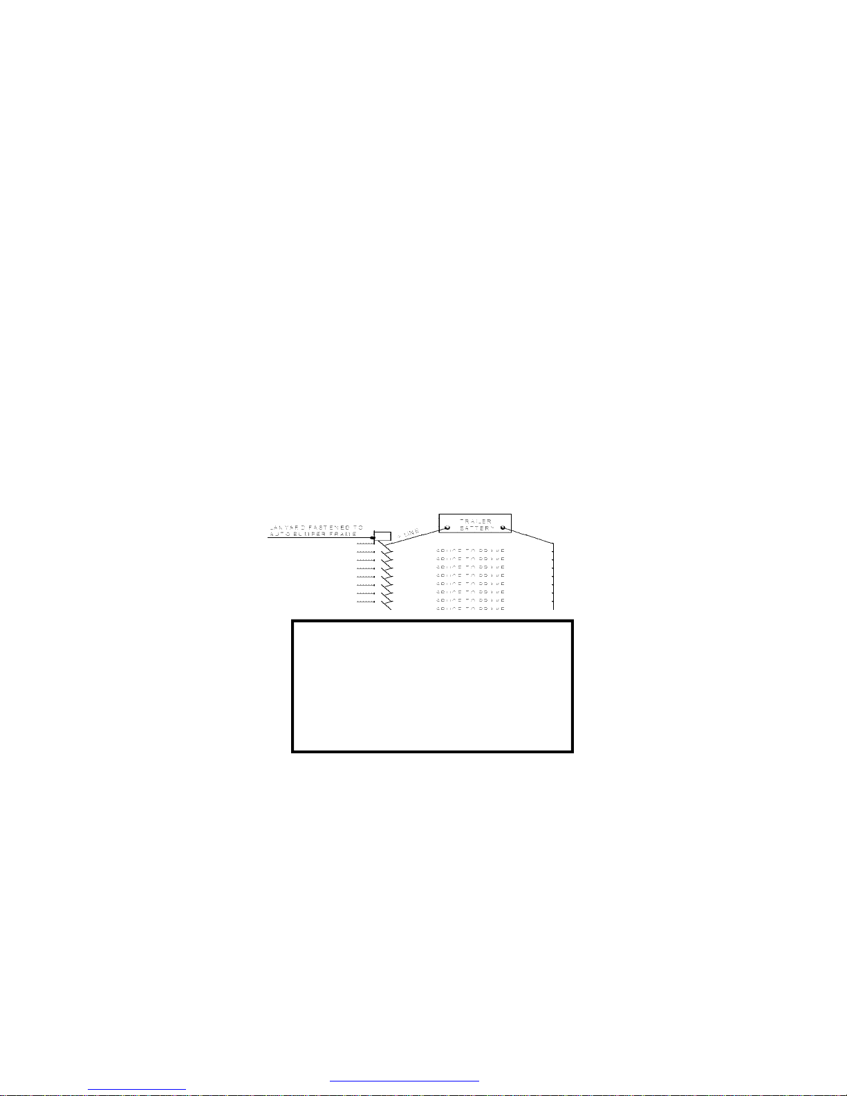
brakes. This system will apply the brakes of the trailer should it become
loose or detached from the tow vehicle. A 12-volt battery installed on the
coach is required to power the breakaway switch.
Never use this breakaway switch and trailer brake system as a
parking brake. There would be a high amp draw on battery and
converter, potentially causing damaged wiring, connectors, and
breakaway switch plus unnecessary energy draw. When plunger is pulled
with power engaged there is a constant 12 volt draw on energy source to
the brake assembly.
CAUTION; REMOVING PLUNGER WITH POWER TO BRAKES COULD
RESULT IN DAMAGE TO BRAKES.
WARNING; Removing plunger while in storage could result in
corrosion of unit points.
WARNING;A tag may be attached to lanyard cable: DO NOT use as a
parking brake.
SAFETY BREAK-AWAY SWITCH
WILL NOT OPERATE
Unless connected to a power source
equivalent to or greater than an auto
-motive type 12 volt, 12 amp hour
wet-cell battery.
SETTING UP AND USING YOUR RECREATIONAL VEHICLE
We recommend that you select a level or nearly level place for camping.
There are two reasons to be level. First, all components in your coach,
such as your water drainage system and especially your refrigerator, are
designed to operate in a level position. Second, it is more comfortable to
28
PDF created with pdfFactory trial version www.pdffactory.com
Page 36

live on the level. Should a level site not be available, use short 2 x 6 inch
blocks of wood to raise the low side wheels to a level position.
Before unhooking the trailer from the tow vehicle, be sure the jack foot is
in place on the tongue jack and block the trailer wheels to keep the trailer
from moving.
Before lowering the tongue jack, you may wish to place a wood block or
hard support under the foot of the jack, unless you are on a cement slab.
This helps to prevent the jack from sinking onto the dirt.
Travel Trailer Hook Up
1. Release the weight distributing bars (if used).
2. Release the safety latch on the coupler.
3. Raise the coupler on the A-frame by turning the tongue jack until the
ball is free.
4. Disconnect the 7-way wire connector, safety chains, and the
breakaway cable.
5. Raise front jack until Tow vehicle will clear coupler. Drive Tow vehicle
away.
6. Now raise/lower front end until coach is level.
7. Lower stabilizer jacks to desired position to stabilize coach.
8. Reverse procedure to hook up coach to tow vehicle.
The use of stabilizer jacks on a recreational vehicle is a popular and
useful option. They provide a reasonable amount of stability while using,
occupying, and moving around in your camper. It is important to
remember that stabilizer jacks are for support of the coach and are not
designed to bear the weight of a recreational vehicle.
To operate the stabilizer jack, place crank onto the jack shaft and turn
clockwise to lower until the frame begins to raise slightly. Equalize all four
jacks for best support. You may need to adjust each jack two or three
times.
To raise jack to upper travel position, insert crank and turn
counterclockwise until jack is seated in UP travel position.
Upon completing the setup of your coach, you are now ready to make
attachments to various facilities:
v Waste water hose connections.
v 110-Volt power cord electrical hookup.
29
PDF created with pdfFactory trial version www.pdffactory.com
Page 37

v Turn on propane tanks and light pilot lights, if any, on
appliances. Remember there may be air in your propane lines. Be
sure to bleed them before planned usage.
v Open any windows and roof vents as desired for ventilation.
v Fresh water connections.
You may have additional accessories and options, such as an awning on
the door side which need to be opened. Separate instructions are
provided by the manufacturer of these components.
When preparing to depart or move, don’t forget to reverse the preceding
procedure. Remember, open windows, or roof vents left in the up position
are subject to wind damage in transit.
GENERAL DETECTOR INFORMATION
As you are confined in a RV which is much smaller than a standard
house, you must realize safety detectors will be activated much sooner
than in a residential house, due to there being much less air volume.
TEST ALL SAFETY ALARM OPERATION AFTER VEHICLE HAS BEEN
IN STORAGE, BEFORE EACH TRIP, AND AT LEAST ONCE PER WEEK
DURING USE.
Each listed detectors has it’s own manual and instructions sheet,
providing more information for it’s use and maintenance.
Life time of each detector ranges from five to ten years and will need to
be replaced as per manufactures instructions.
SAFETY DETECTORS—3
Fire Extinguisher—#1
Fire extinguisher is installed in each vehicle and is located near the
entrance door in the RV. Be familiar with it’s location and operating
instructions as printed on the extinguisher. Inspect your fire extinguisher
at least twice per year or more, as instructed on the extinguisher.
CAUTION
!
30
PDF created with pdfFactory trial version www.pdffactory.com
Page 38

Propane/Carbon Monoxide Detector —#2
Any recreational vehicle which contains a propane fuel system with
propane consuming appliances requires a propane leak detection device
for safety protection. Currently this detector also serves as a carbon
monoxide protection device. A converter or auxiliary battery is required
to supply 12-volt DC energy to operate the device. There is no master
cut-off switch to disengage detector.
WHAT IS CARBON MONOXIDE?
Carbon Monoxide (CO) is a highly poisonous gas which is released
when fuels are burnt. It is invisible, has no smell and is therefore very
difficult to detect with the human senses. Under normal conditions, in a
room where fuel burning appliances are well maintained and correctly
ventilated, the amount of carbon monoxide released into the room by
appliances is not dangerous. These fuels include: wood, coal, charcoal,
oil. natural gas, gasoline, kerosene, and propane. Such gases can build
up in the blood, interfering with the body’s ability to supply oxygen to
itself.
Because CO is a colorless, odorless, tasteless, and highly poisonous
gas that prevents the blood from carrying oxygen to vital organs, CO is
200 times more likely to replace oxygen in the blood. It can endanger
lives even at low levels of concentration.
DUAL SENSOR TECHNOLOGY
The SAFE-T-ALERT 35 series combination CO/Propane Gas Alarm is an
alarm that combines into a single, compact system a powerful alarm that
detects both Carbon Monoxide (CO) and explosive gases propane.
The 35 series uses the latest microprocessor technology combined with
two electronic self-cleaning sensors that operate independently of each
other. The combined unit can detect CO and explosive gases
simultaneously.
OPERATION
When the unit is first powered up, the CO sensor requires a ten (10)
minute initial warm-up period to clean the sensor element and achieve
stabilization. The GREEN LED indicator will flash on and off during the
10 minute warm-up period. The unit cannot go into a CO alarm during
the warm-up period. To test your unit during the warm-up period, press
31
PDF created with pdfFactory trial version www.pdffactory.com
Page 39

the test button. See Test Procedure in this manual. After the warm-up
period, the GREEN power ON indicator should glow continuously. If the
ON indicator light does not light, see the section, Trouble-Shooting
Guide, in the user’s manual for further information. Do not attempt
to fix it yourself.
Gas Alarm: When you power the alarm, it has a warm-up period of
approximately 1 minute. This unit cannot go into a gas alarm during the
warm-up period. After 1 minute the alarm can detect explosive gas and
will energize the relay on models 35-742-R and 35-742-R-MS.
Simultaneous CO and Gas Alarms– Because the risk of a propane
gas explosion is generally a more serious danger, your alarm unit gives
the gas alarm a higher priority during simultaneous alarm condition.
If your unit generates alarms for both Gas and CO at the same time, the
gas LED will flash red and the beeper will sound. The CO LED will be a
solid Red until the CO is ventilated out of the RV, at which time the LED
will return to the Green operational/safe color.
Brownout Protection— The unit can tolerate short power interruptions
and brownouts where the circuit voltage drops as low as 1 VDC. If the
brownout lasts too long, the unit will reset and operate as described
above.
LOW POWER OPERATION
This alarm will operate normally down to 7 VDC. Do not operate this
alarm below 7 VDC.
VISUAL AND AUDIBLE ALARM SIGINALS
This SAFE-T-ALERT™ CO/Propane Gas Alarm is designed to be easy-to
-operate. The alarm has two indicator lights that display a specific color
for each monitored condition. There also is a matching sound pattern for
alarm conditions.
CO ALARM
The Red CO LED will flash and the alarm will sound 4 “BEEPS” then be
silent for 5 seconds. These signals indicates that the CO level is over 35
ppm. IMMEDIATE ACTION IS REQUIRED. See the Procedures To Take
During An Alarm in the user’s manual that is supplied with the
detector. This cycle will continue until the TEST/Mute button on the front
32
PDF created with pdfFactory trial version www.pdffactory.com
Page 40

of alarm is pressed. Ventilate the RV. The RED light will stay ON until the
CO has cleared, or the alarm will reactivate in approximately 6 minutes if
the CO is still present. DO NOT RE-ENTER THE RV. This alarm will
return to normal operation after the RV’s properly ventilated.
PROPANE GAS ALARM
The RED LED will flash and the alarm will sound a steady tone whenever
a dangerous level of propane or methane gas is detected. IMMEDIATE
ACTION IS REQUIRED. See Procedures To Take During A Gas
Alarm. The detector will continue to alarm until the Test/Mute switch
on the front of the alarm is pressed. Ventilate the RV. The RED Gas LED
will continue to flash until the gas has cleared, or the gas alarm will
reactivate in approximately 5 minutes if the gas is still present. DO NOT
RE-ENTER THE RV. This alarm will return to normal operation after the
RV is properly ventilated.
MALFUNCTION/SERVICE SIGNAL. If any malfunction is detected,
the Gas LED will remain off and the Operational/CO LED will alternate
Red/Green and the alarm will sound once every 15 seconds. Press the
Test/Mute button. If the Test/Mute button does not clear signals, check
the battery voltage. If the battery voltage is not low and the unit will not
return to normal operation, immediately remove the alarm and
return for service or warranty replacement.
OPERATION SIGNAL AUDIBLE SIGNAL VISUAL SIGNAL
NORMAL NONE STEADY GREEN
CO ALARM 4”BEEPS” STEADY RED
5 SECONDS OFF
PROPANE ALARM CONSTANT FLASHING RED
ALARM “BEEP” EVERY ALTERNATING
MALFUNCTION 30 SECONDS RED/GREEN
END OF LIFE BEEP EVERY RED/RED
30 SECONDS GREEN/GREEN
FLASHING
END OF LIFE SIGNAL
All 35 series models include an End of Life (EOL) Signal indicating the
sensor has the end of it’s service life and you MUST replace the alarm.
33
PDF created with pdfFactory trial version www.pdffactory.com
Page 41

The signal is the LED flashing. RED/RED GREEN/GREEN with a beep
every 25-30 seconds. The EOL signal may be reset by pushing TEST/
RETEST button on the alarm. This will reset the EOL signal for a period of
72 hours for a total of up to 30 days. After 30 days the signal cannot be
reset and the alarm MUST be replaced. DO NOT DISCONNECT THE
ALARM UNTIL YOU HAVE A REPLACEMENT ALARM AVAILABLE TO
INSTALL.
WARNING!
!
LIMITATIONS OF CO AND GAS ALARMS
THIS ALARM WILL NOT WORK WITHOUT POWER
Some reasons for no alarm power are; a blown or missing fuse in 12V fuse
panel; broken wire; a faulty wire connection or circuit breaker; a discharged
battery; cut lead wires, or improper supply (+) or ground (-) connections.
Smoke Alarm—#3
Smoke alarms are required when propane is used in coach and open
flame cooking happens. Alarm is placed on ceiling between bedroom and
kitchen.
Energy to operate is supplied by a 9 volt battery inside of alarm.
Operation: The smoke alarm is in operation once the battery is
correctly connected. The LED will flash every minute to show the battery
is supplying power to the alarm. When production of combustion are
sensed, the unit sounds a loud alarm which continues until the air is
cleared.
Each smoke alarm has its own manual and is normally found in your
supplied materials with coach.
TESTING
Test the alarm by pushing the test button on the smoke alarm cover for at
least three seconds, until the alarm sounds. The alarm sounds if all
34
PDF created with pdfFactory trial version www.pdffactory.com
Page 42

electronic circuitry, horn and battery are working. If no alarm sounds, the
unit has a defective battery or other failure and should be replaced
immediately.
• Test each smoke alarm weekly to be sure it is installed correctly and
operation properly.
• Test smoke alarms after the recreational vehicle has been in
storage, before each trip, and at least once a week during use.
• Stand at arm’s length from the smoke alarm when testing. The alarm
horn is loud to alert you to an emergency. The alarm horn may be
harmful to your hearing.
• The test button accurately tests all functions. DO NOT use an open
flame.
Smoke alarm will NOT sound in and of flames—only smoke.
-
!
Test smoke alarm operation after vehicle has been in storage, before each trip, and
at least once per week during use. Failure to comply may result in serious injury.
STEPS
(Two or Three)
Before entering your recreational vehicle place your hand in the center of
the step assembly. Pull the step outwards. The step assembly will raise
slightly and then out, away from the coach. The lower step will unfold
180° to useable position. The arm on the step will meet a positive stop.
Step care, maintenance and lubrication will be found in the maintenance
manual.
!
After lubrication, be sure no lubricant is remaining on step, causing a person to slip.
WARNING
CAUTION
35
PDF created with pdfFactory trial version www.pdffactory.com
Page 43

Windows
All windows are of slider opening design, solid picture window, or opening
vent panels. Sliders may open horizontal or vertical as called for per floor
plan. Egress windows have an unlocking handle or two small hinged
clips on each side. After unlatching, the panel will swing out on a top
hinge. On some egress windows, screens are attached to the swing out
panel of window.
Doors
Locks on entrance doors have two lock mechanisms, a deadbolt in the
frame section of lock and a standard lock in the handle. Both locks use
the same key.
Screen doors usually have a hook/lever type of latch. Pull lever
downward to release screen door.
Locks on trunk doors need a small quantity of silicone lubricant sprayed
internally two times per year to keep functioning correctly.
TV Antenna
The stationary TV Antenna has a rigid base to mount the receiver head
which cannot be rotated or raised up.
Base is attached to roof with 4 screws and the antenna is attached with
two bolts and nuts.
Inside of coach, on the wall is a power supply with a brown cover where
you hook-up to TV and Satellite. There is an on/off button on the power
supply to engage the booster, located inside of the antenna head.
This antenna also serves as a radio receiver for the sound system in the
coach.
Location of this power supply is:
1. On the wall, above the space for TV, free standing or wall
mounted.
2. Behind the TV.
3. Possibly on the ceiling close to TV location.
36
PDF created with pdfFactory trial version www.pdffactory.com
Page 44
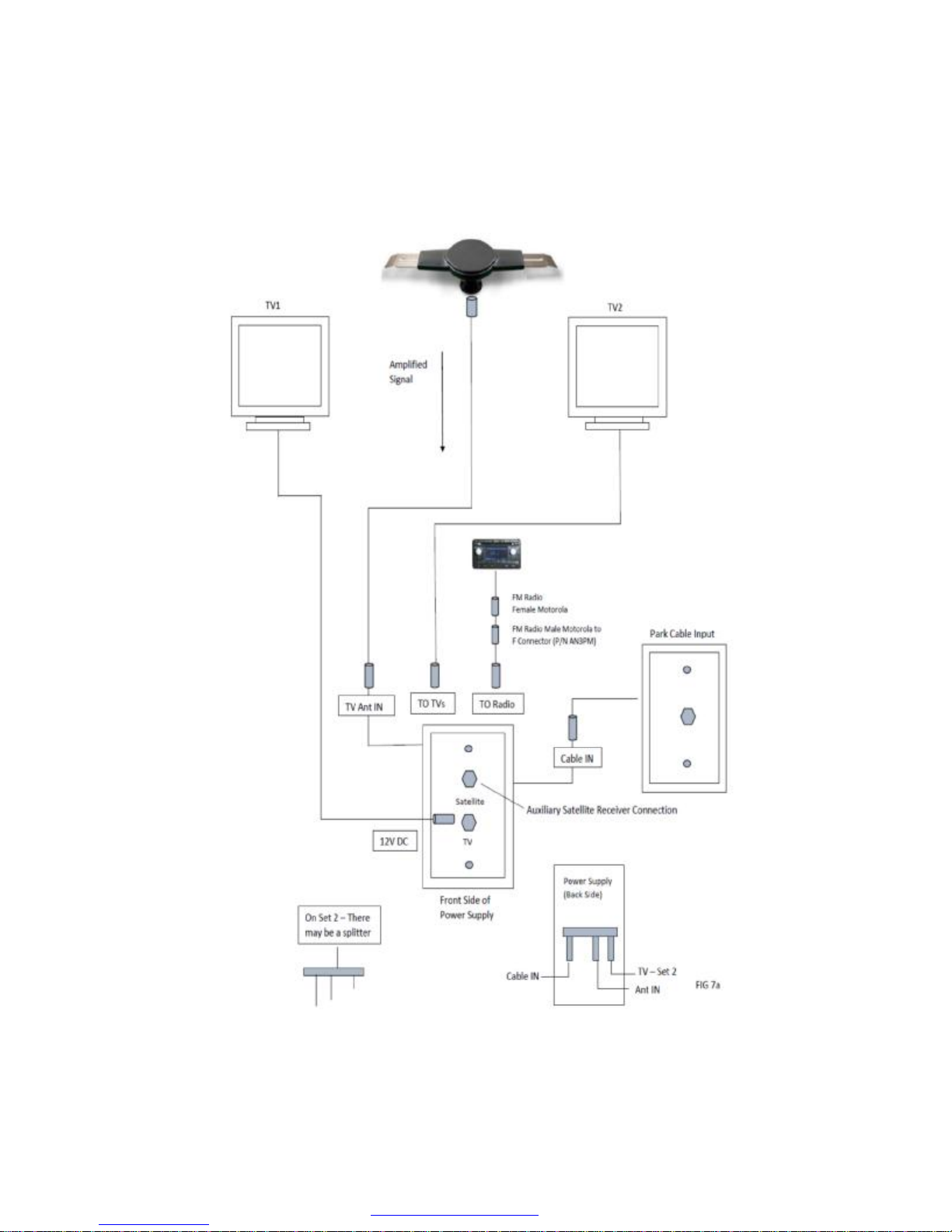
37
PDF created with pdfFactory trial version www.pdffactory.com
Page 45

NOTE: The Venture, Sonic models that have slide-outs, use one of
the following slide-outs that are listed.
SLIDE-OUTS
With different models of trailers, VENTURE RV uses numerous slide out
systems as listed below, followed by descriptions. Several different
vendors supply components, loose and/or attached to frames.
1. Below floor system - All metal components are external, located
under floor and in frame, inside of enclosed underbelly cover.
2. Above floor system - All components are inside and above floor, to
be found under dinette or sofa slide out.
Before operating the power slide-out system in your coach, read and
become familiar with these instructions, along with components and
operation methods. Most of these components are enclosed and can’t
be seen.
POWER FOR OPERATION
All power slide systems operate on 12 volt DC power provided by a fully
charged auxiliary battery, which is an aftermarket item, and a converter.
Thru a 12 volt distribution load center, breakers are provided for each
slide. For best performance, have 120 volt AC power attached to your
coach, feeding the distribution load center. Tow vehicle 12V power may
also be used as required.
A automatic reset breaker is located in the distribution box feeding the
operation switch to the motor.
Supplement your battery by either one of two choices:
1. Hook up a 120-volt AC power cord to recreational vehicle for
converter operation.
2. Use 12 - volt power through the tow vehicle to the recreational
vehicle battery or batteries.
Either of these methods will help ensure maximum electrical power for
the slide-out motor, as well as maintain your battery.
38
PDF created with pdfFactory trial version www.pdffactory.com
Page 46

TRAILER SET-UP REQUIREMENTS - GENERAL
Note:
1. Before operating the slide-out room, level the trailer front-to-rear and
side to side.
2. Extend all stabilizer jacks to make solid contact with the ground and/
or on solid blocks. Placing stabilizer jacks onto a hard surface allows
the coach to remain square and assure a good weather tight seal
between the room and trailer sidewall.
!
♦ Always make sure that the trailer is level before operating the slide-out room.
♦ Always make sure there are no obstructions blocking the path of the room when it
is moving.
♦ Always make sure that the room path is clear of people and objects before operat-
ing.
♦ Always keep away from the slide rails under the coach when the room is in mo-
tion.
FAILURE TO FOLLOW THESE INSTRUCTIONS COULD RESULT IN SERIOUS INJURY
BELOW FLOOR SLIDE SYSTEM
Under floor slide-out mechanism steel bars are welded to the frame
members. A “cog” track is welded to bottom side of cross member,
matching with a gear attached to drive shaft, “LCS (Lippert Component
System.) As motor turns, a actuator moves the gear on the track
( ram ). A cross shaft, front to rear ram connects the second ram,
moving the opposite end of slide. Mechanism operates the same, flush
or standard floor.
ABOVE FLOOR SLIDE-OUT
All components are located inside of coach, under dinette or sofa. Base
is attached to the floor and sidewall. Top portion has a “cog” track
attached to a “ram” which matches to gear on motor. As motor runs, it
moves the slide in or out, as you choose. On a large slide with 2 units, a
cross shaft will connect both units, operated by one motor. Access to
these components is inside of coach, under slide floor.
WARNING
39
PDF created with pdfFactory trial version www.pdffactory.com
Page 47
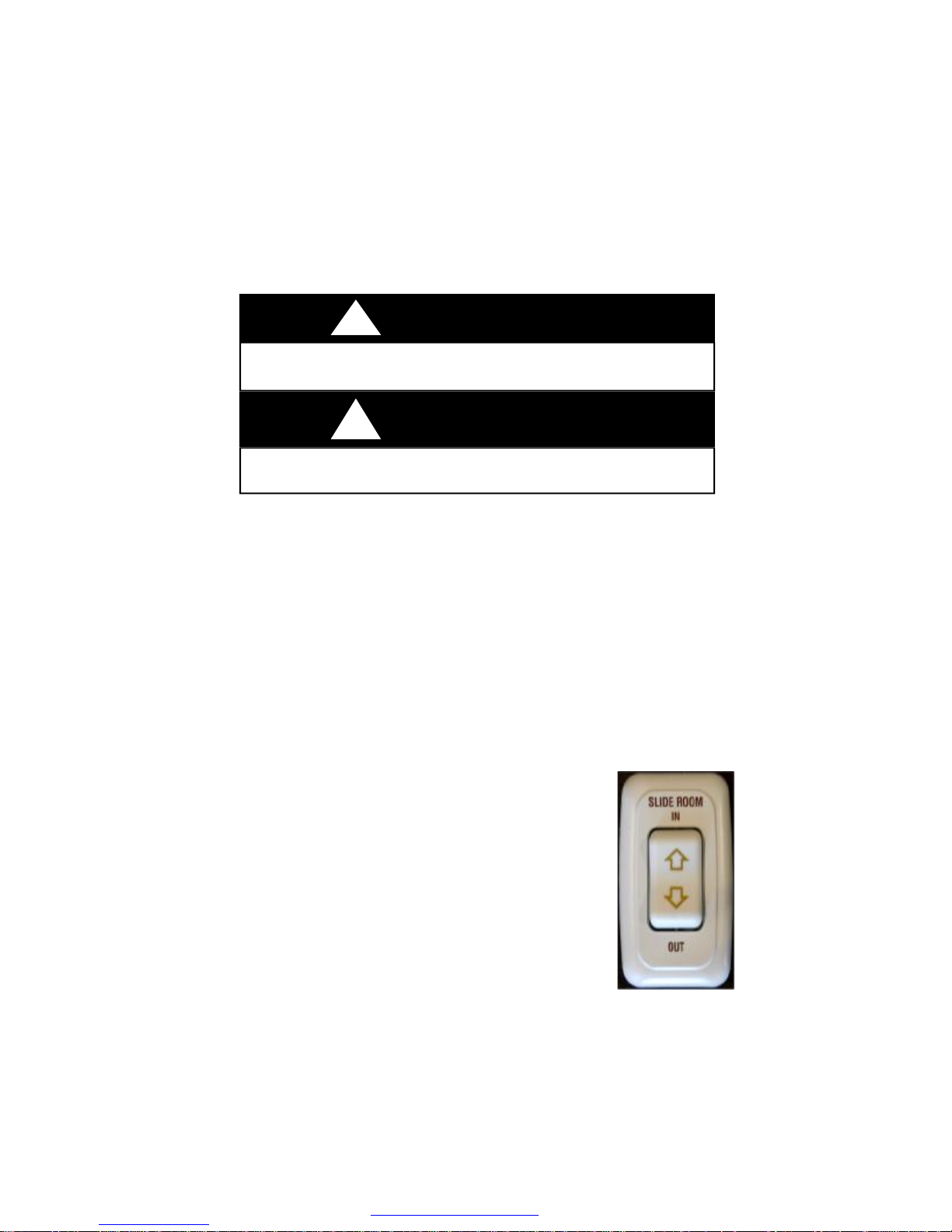
OPEN : Hold operation switch until room seals tightly on the
exterior of the unit. DO NOT distort or bend the exterior flanges or
interior fascia by holding the switch in the “ON” position.
CAUTION
!
When opening slide room, DO NOT over-extend. Fascia board can be distorted,
loosened or bent from correct position
!
Stand clear of the room’s interior path and verify that the room’s exterior path is
clear before extending or retracting the room.
CLOSE : To retract, reverse the procedure and hold button until the
room is fully inside with gaskets sealing to the outer wall. It takes about
20 seconds to move the slide in or out.
VENTURE RV does NOT require or suggest blocking, supports,
jacks, etc., to be used under slide outs during extended normal use.
Electrical Components
A 12 volt DC motor is located under the frame. It may be inside of main
rail on frame, or on some models it will be on the outer side on main rail
along with front to rear shaft. On the above floor slide, it will be under
the floor of the sofa or dinette. The in wall slide room system motors are
installed in the wall.
Operational switch: This switch, is a three position, (off
center, in or out) spring loaded switch. Select which
direction you wish to move the room. Press on desired
position and hold until room is seated, and gasket is
slightly compressed. Do not force the room to move
beyond sealing as damage could occur.
WARNING
40
PDF created with pdfFactory trial version www.pdffactory.com
Page 48

Because operating the slide-out draws up to 15 amp current from the battery, some
source of supplemental charging should be operating while extending or retracting
the slide out
MANUAL OVERRIDE:
BELOW FLOOR SLIDE OUT
Should a power failure occur (no 120 volt AC power or the battery looses
its charge), follow the directions listed.
There is a 1/2” shaft coming through the main rail of frame. On the
end of the shaft is a 3/4” nut attached. Use a 3/4” socket with extension
and ratchet to move the slide. On some units the stabilizer jack crank
handle will also work on this shaft with the attached 3/4” nut.
ABOVE FLOOR SLIDE-OUT
Manual Override (Single or Double Rams)
Should 12 volt power fail and there is no 120 volt AC power available,
follow the directions listed.
Access to the ram is under the floor of slide, sofa or dinette, and is from
the front. Lippert Component System has a smaller motor, less draw and
requires a 5/8” socket, ratchet and probably an extension shaft.
BLINDS
Any blinds with loose cords, such as mini-blinds CANNOT be installed in
bunks designed and built for young children.
Night shades installed, have cords anchored to lower part of window and
need to be secured for operation.
VENTURE RV recommends these shades be in the UP position for
travel to avoid lower metal holder being in contact with garnish on
window.
!
CAUTION
41
PDF created with pdfFactory trial version www.pdffactory.com
Page 49

WARNING
!
These individual tassel cords reduce the strangulation hazard in the pull cord by removing the loop.
Do not tie cords together. Check periodically to make sure the cords have not twisted
into a loop.
!
While traveling, all mini blinds need to be in :up “ position to avoid swinging and
scratching paneling. Even with brackets at lower part on window, pull blinds up before
traveling.
Loose furniture, such as dinette and free standing chairs, need to be
secured to prevent movement, contacting walls and causing wall and
chair damage during travel.
CAUTION
42
PDF created with pdfFactory trial version www.pdffactory.com
Page 50
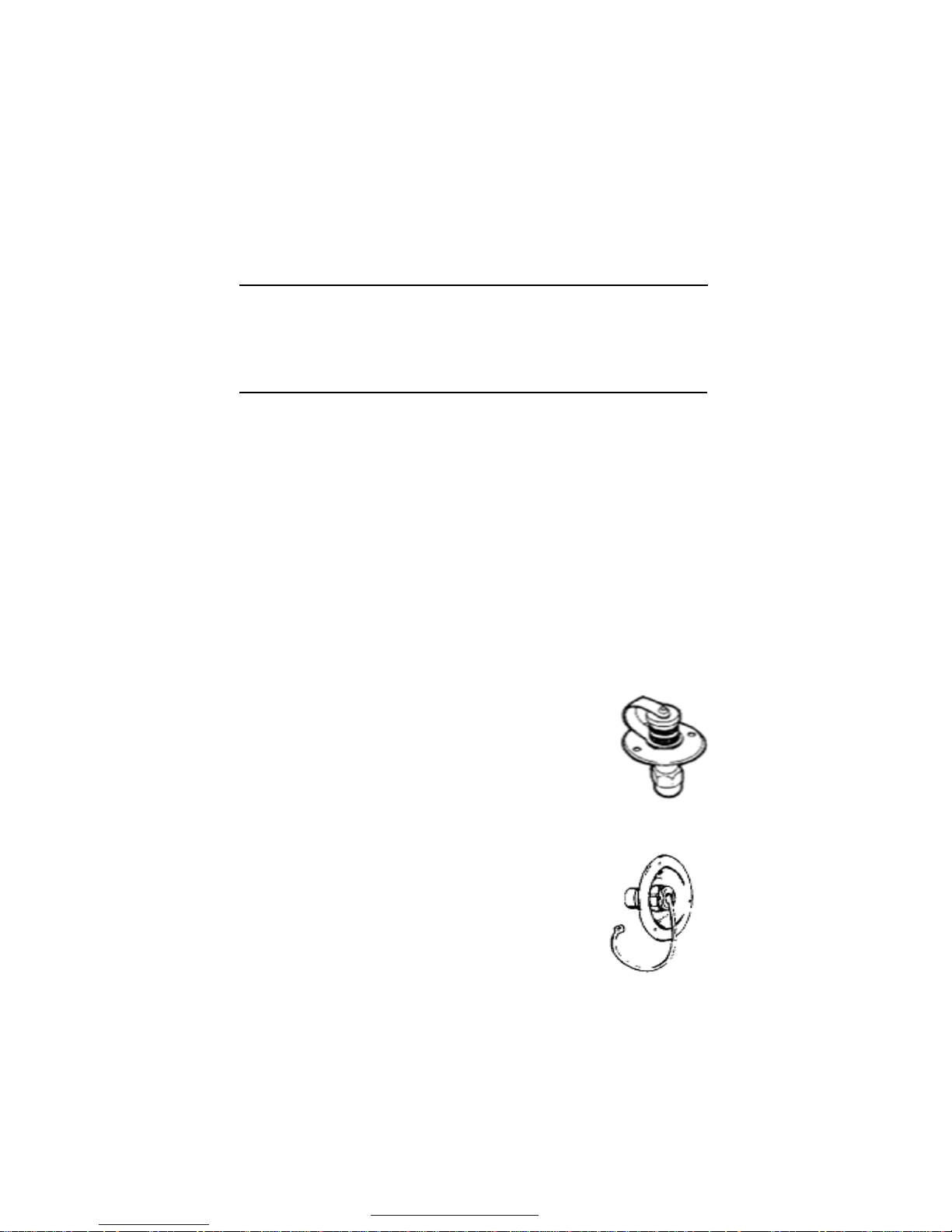
CHAPTER 4
SYSTEMS
WATER AND DRAINAGE PLUMBING_______________________
Your Venture recreational vehicle has a complete water system, to
carry fresh water, as well as holding tanks for used water. Each
group has its own explanation along with its own operation.
FRESH WATER SYSTEM_________________________________
Tanks
Fresh water tanks are located and installed under the coach
between frame members and protected with a cover, plus a steel
carrier.
All water containers have 3 exits; (1) draw water with pump
throughout the coach, (2) drain spigot for tank, (3) overflow line
attached to fill vent in gravity fill.
Filling Fresh Water System
To place water in to your coach fresh water system, use one of the
following methods.
A. City Water Fill See Figure 1
Water is received into the system through
a direct hookup, referred to as “city water
fill”. Attach a hose to the hook up and
supply line. Open the faucet from the
supply line. Enter the unit, and open any
faucet, to allow air to escape, as there
will be some air pockets.
B. Gravity Water Fill See Figure 2
To place water into the fresh water tank, remove
cap from fill. Insert water hose 4 to 6 inches into
the 1 1/4” flex tube. Open the water supply
faucet. DO NOT overfill the tank as it could burst.
It IS NOT designed to hold pressure. On the fill is
a small screen, 1/2 inch at the 10;00 o’clock position. When water
starts to come out—STOP FILLING NOW! It is the vent.
Figure 1
Figure 2
43
PDF created with pdfFactory trial version www.pdffactory.com
Page 51

CAUTION
DO NOT leave tank unattended while filling, as an over filled tank will built
pressure, causing tank to crack, rupture, and leak or even damaging sup-
!
ports holding it in place.
CAUTION
Excessive pressure from water supply systems may be encountered in
some parks, especially in mountain regions. Water pressure regulators are
available to protect your system against such high pressure. A regulator at
45 pound rating is recommended to prevent damage to the plumbing system or components.
12-Volt Demand Pump
When water is desired and you are not hooked up to city water, your
tank will be your supply. On your monitor panel is a switch to turn
on the 12-volt demand pump. Energy for the pump is supplied by
the auxiliary battery or converter. The pump will self-prime when
started, supply water, and continue to run until approximately 40
pounds of pressure is achieved. When pressure drops to 20
pounds, pump will restart. Some cycling in pump may occur. A
check valve is built within the pump to prevent water from flowing
into the supply tank.
The pump has a small filter attached on the “in port “ side to prevent
any foreign matter from entering the pump. You need to annually, or
even more often, remove the lower cup and clean it out.
When pump is not in use, turn 12-volt power off at the switch.
Occasionally your water pump may start/stop quickly ( within a
second ). This is referred to as “cycling”. The cause for this annoying
noise may be a slightly open faucet, water saver washer in the end
of the faucet spout, plus other restrictive issues. If pump cycles
every 10 to 15 minutes, there may be a slight water leak
somewhere, check valve in city water fill, plumbing fittings or
pressure valve in pump.
!
44
PDF created with pdfFactory trial version www.pdffactory.com
Page 52
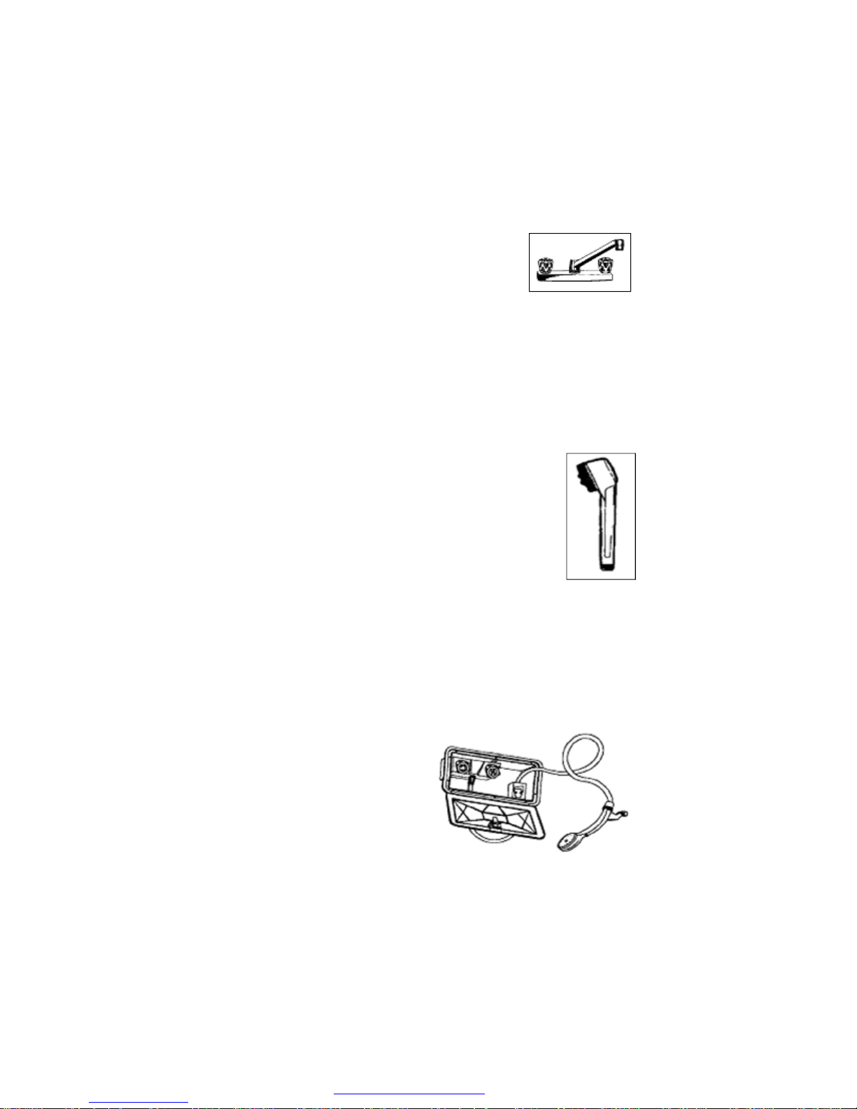
Faucets
The basic operation of a faucet is the same as in
your home. Open the knobs for water supply.
Close faucets when sufficient water volume is
achieved. It is normal to experience occasional
air pockets in the system.
Bath and Shower
Your bathtub and shower are built with Vinyl, Fiberglass, or ABS
plastic material, similar to those in your home. Shower curtains are
provided with the coach and must be used to prevent water from
spilling onto the floor, possibly causing damage.
The shower head used in the bathroom has a non-positive shutoff
valve and will drip slightly in shut-off position. A
vacuum breaker is also built into the faucet to permit
water in hose to drain out as a code requirement.
Before beginning your shower be sure the water heater
is lit. Adjust the faucet for desired temperature before
entering the tub or shower. When shower is completed,
be sure to turn water off at the faucet.
Used water will drain through the plumbing pipes into the gray water
holding tank. Remember capacities of your water heater and gray
water holding tank. Long showers in a recreational vehicle are NOT
suggested due to the amount of water that is available. To conserve
water, wet down, and turn water off while you soap up, then rinse.
Outside Shower (Optional)
A convenient faucet assembly with
hot and cold water is available for
exterior use washing or rinsing on
the outside of camper, such as
washing hands and utensils.
To operate the outside shower:
1. Open the door with key and
allow lid to hinge down.
2. Remove the shower head and open valve.
3. Open the faucet valves and adjust to the desired temperature.
45
PDF created with pdfFactory trial version www.pdffactory.com
Page 53

4. To end operation close valve (s) on the faucet and allow water to
drain from the shower head.
5. Close the valve on the shower head.
Any water remaining in the hose will drip or run out of the vacuum
breaker. This is NOT a leak but performs as intended. Water in the
ABS plastic box will drain out along outer edge.
The shower head can be removed to drain the hose faster.
Reassemble and place onto bracket. Keep the door closed when
not in use for sanitary reasons.
Fresh Water Line
Two lines, generally red for hot and blue for cold, transport water
through out the coach. Valves to direct flow are near city water fill or
pump area. Connector elbows and tees are plastic or copper, and
are held together with compression rings for no leakage.
Low-Point Drains
Low-Point drains are placed on recreational vehicles to drain water
lines, tanks, and water heater to prepare coach for winterization and
sanitizing systems.
Fresh water supply tanks will have their own separate drains under
the floor and/or frame, with a valve to be opened to drain, over flow
drain line may be close by.
Plumbing lines also have Low-Point drains located in various areas.
You may find them (2) for hot and cold water lines coming out of
storage areas, outer metal skirt, through under belly covers, control
centers, etc. Water should always drain out to the ground, not into
underbelly cover.
!
WARNING
POTABLE WATER ONLY. SANITIZE, FLUSH AND DRAIN
BEFORE USING. SEE INSTRUCTION MANUAL. FAILURE TO
COMPLY COULD RESULT IN DEATH OR SERIOUS INJURY.
46
PDF created with pdfFactory trial version www.pdffactory.com
Page 54
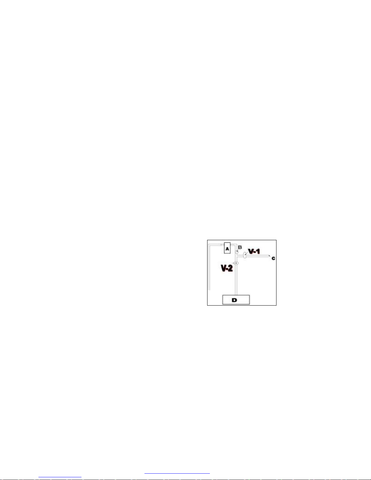
Sanitizing and Filling the Potable Water System
For your safety, you should sanitize your potable water system when
your recreational vehicle is new or when it has been sitting unused
for a period of time such as over winter, and it may have become
contaminated.
Prepare a chlorine solution using 1/4 cup of bleach (5% sodium
hypochlorite solution) to one gallon of water. Prepare one gallon of
this solution for each 15 gallon capacity of the tank. As designed
and constructed, this method will sanitize the plumbing system.
For Water Lines only
1. Close all the drains, tanks, lo-point drains, and have by-pass
closed to water heater.
2. With the coach completely drained, with V2 valve closed, open
V1 valve and insert siphon hose into container with sanitation
solution. Valves and hose are located by water pump in side
compartment or in a cabinet. Start the pump to draw liquid into
the system until liquid comes through the faucets. Close faucets
and pump will shut off. Lines are now
full.
3. Should you desire to sanitize the tank
also, pour sanitation solution into the
gravity water fill, which will drain into
the fresh water tank.
A = Pump
B = Filter
C = Siphon Hose
D = Tank
V-1 = Valve
V-2 = Valve
4. Add additional water to the tank through the gravity water fill.
Open faucets, close V-1 valve, V-2 valve needs to be open.
Start the pump to draw the liquid from the tank through the
water system. When liquid flows freely from the faucets, close
faucets. Pump will shut of
5. Allow this water solution to stand in the system for three hours.
6. Drain solution and flush with fresh water.
7. To remove any excess chlorine taste or odor, prepare a solution
of one quart vinegar to five gallons of water and allow this
solution to agitate in the tank for several days by vehicle motion.
8. Drain the tank again and flush with fresh water.
47
PDF created with pdfFactory trial version www.pdffactory.com
Page 55

9. Your demand water system is now ready for use.
10. Be sure to TURN OFF the pump when traveling or when the
recreational vehicle is not in use.
Your water system is now ready to be used. When sanitizing is
completed, remember V-1 valve needs to be closed, and V-2 valve
needs to be open for normal use.
The slide outs containing kitchens, will have flexible hoses installed
on both fresh water lines and drain lines. Make sure there are no
obstructions to allow free flow, and prevent any leakage.
Drainage (Fresh Water)
All permanent fresh water tanks can be drained. The type of drain
used is a turn valve with open/close position. This drain is located
under the floor.
To drain the supply lines and the entire system, you need to follow
the steps listed below. Locate the valve placed at the floor level or
close to the floor, found under the dinette, storage cabinet, or sofa.
These valves will be at the lowest point of the water lines.
To Drain System:
1. Open all faucets including optional exterior shower.
2. Open the fresh water tank drain.
3. Open the water heater drain.
4. Open all (two to four) low-point drains.
5. Open the toilet valve, hold or block if need be.
6. To empty the pump, start and allow to run up to 20 seconds.
Sanitation System
Toilets
The toilet used in this model, is a Thetford,
Aqua Magic Residence, with foot flush.
Prior to using your toilet, be sure to add a proper
amount of deodorant chemical into the toilet with
water. Flush contents into tank plus two or three
gallons of water.
After each flush, about two inches of water will be in bowl, which is
fine for travel.
48
PDF created with pdfFactory trial version www.pdffactory.com
Page 56
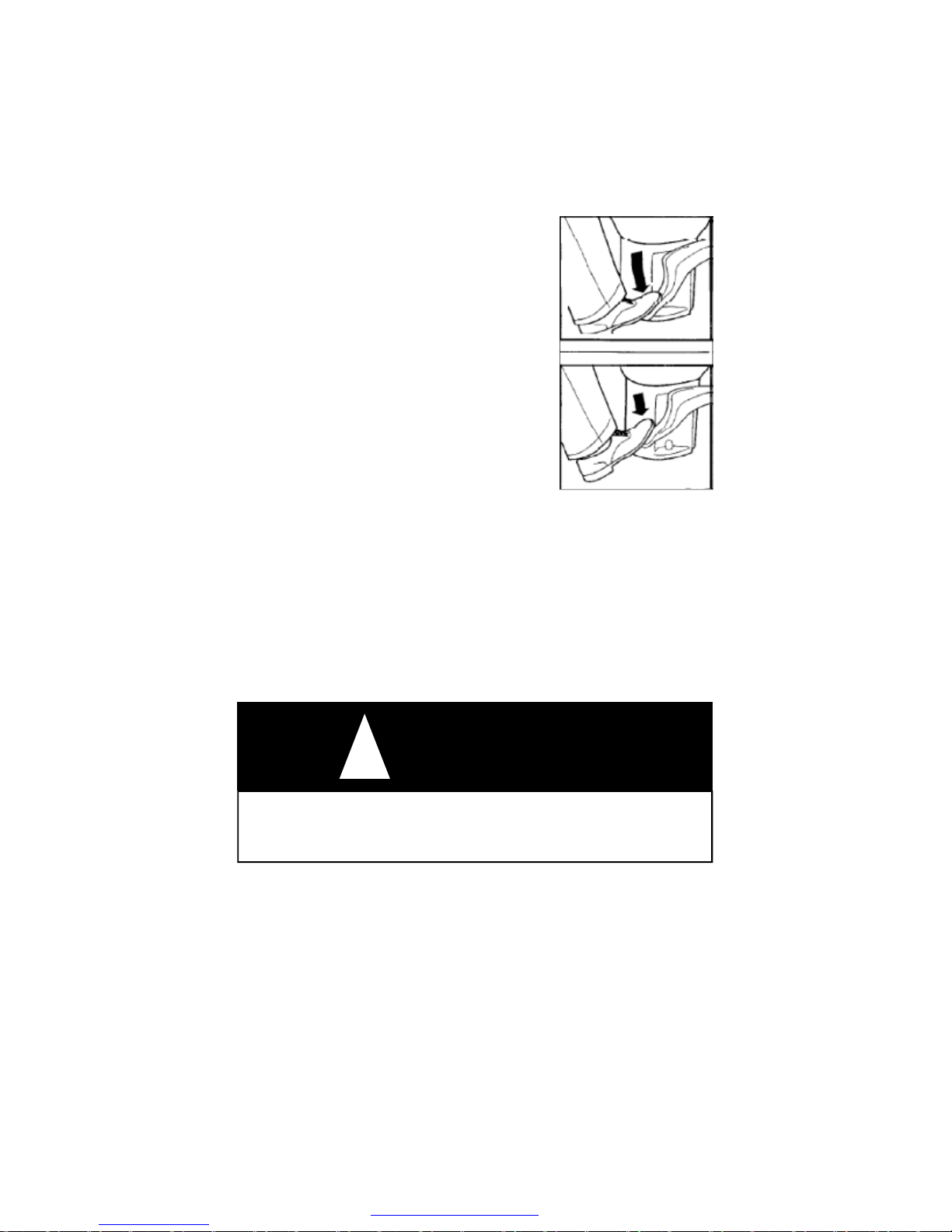
OPERATION: Note the photos showing
movement of pedal downward. To flush,
press pedal all the way down. To add water,
press pedal halfway down.
When hooked up to a sewer drain at a camp
ground, ALWAYS keep the termination valve
CLOSED until the tank is at least 3/4 full.
This will provide sufficient water to assist in
complete draining of tank.
Manufacturer of toilet, Thetford Corp., offers a
complete line deodorants, chemicals, and
other convenience products for your use.
Your dealer can assist you with these needs
and may already have them in stock.
Using Toilet and Tank System
When camping you should always have 4 to 6 inches of water in the
toilet bowl. The toilet system performs better when you run water 10
to 20 seconds after flushing to ensure wastes will proceed to the
bottom of the tank. Unlike your toilet at home which uses four to
seven gallons per flush, the average recreational vehicle system
uses two to three quarts. If there is not sufficient water used during
flushing, waste materials may not evacuate properly from drain line
to tank. Tank and pipes could eventually become clogged.
CAUTION
!
NEVER leave the gate valve of your coach’s sewage tank open when hooked
up to a park’s sewer system. Open only when you wish to drain system.
Vents
A very important part of your sanitation system is the vent system in
your coach. These vents release air from holding tanks allowing
water to enter. Vent pipes are attached to the holding tank, go
through the walls. On some models a portion of vent pipe may be
part of the drainage system referred to as a “wet vent”. As air flows
upward, water will be draining downward.
49
PDF created with pdfFactory trial version www.pdffactory.com
Page 57

CAUTION
Keep drain valve closed. Sewer gases may be present when RV is connected to campground sewage hookup. If drain valve is open, sewer gases may
be vented out the side of the RV. (See owners manual).
Holding Tanks
The final parts of your sanitation system are the holding tanks for
waste materials and water. These are located below the floor of
your coach.
Gray Tank. Waste water from the bath tub, shower and sinks will
drain into this container. No special preparation is required,
however, you may wish to add baking soda or a Thetford chemical
to reduce odors from food particles in the system.
Waste Tank. The toilet drains into the waste or “black” holding tank.
For correct preparation follow the listed steps:
1. Release two quarts of water into the toilet bowl.
2. Place the recommended quantity of chemicals for waste holding
tank as per instructions on the bottle into the toilet bowl.
3. Flush liquids into the tank and allow up to two gallons of water to
flow into the tank.
Each time you drain the tank, you should follow the instructions
listed, before using.
All drain pipes will have a “P-trap” installed into each line. Water in
these traps prevent odors from escaping into the coach. During
travel, water from the P-traps may spill and permit odors into the
coach. These odors come from fats and food particles decomposing
in the tank. By adding water and using a RV approved deodorizing
agent, contents will dissolve faster, keeping the drain lines and tanks
clean and free flowing. These chemicals are available at a RV
supply store.
Draining the Tanks
A final part of your sanitation system is the drainage of holding
tanks. Realizing dump stations will vary, place the coach as level as
possible to make drainage easier. Some tanks drain from the center
!
50
PDF created with pdfFactory trial version www.pdffactory.com
Page 58

requiring unit to be level or slightly up in front. Others will drain from
end permitting a slight tilting to the side which drains are on.
CAUTION
It is important to use adequate water to flush and have several gallons of
water with chemicals in the tank. This helps the flow of wastes and reduces
solid waste build-up.
Remove the cap and attach the adapter onto the valve housing.
Turn the adapter 10º to lock onto the pegs. Attach a flexible sewer
hose to the adapter and secure with a clamp. Place the other end
into the approved sewer system.
You may now open the 3 inch drain valve to drain the sewage tank
first. Open the valve on the gray water tank last to utilize water to
wash and rinse the hose and drain lines.
Most states and parks have strict laws and regulations to prohibit
dumping of wastes of any kind into anything other than proper
disposal facilities or sewer systems. Almost all privately owned
parks have either a central pump facility or offer a campsite hookup
for sewage. You can find lists of many dump facilities throughout
the United States in Woodall’s, Rand McNally Camp Guide, Good
Sam Camp Guide, KOA Campgrounds Camp Guide, or various
other publications. Some fuel stations also have dump stations.
BLACK TANK FLUSH SYSYTEM—OPTIONAL
The flush system is designed and built to rinse the waste holding
tank, AFTER waste tank has been drained completely of water and
solids.
1. Attach a fresh water source to the connection marked “Sewer
Tank Flusher”. Be sure termination valves are open on tanks.
2. Open valve to release water into tank for rinsing and cleaning of
your waste water holding tank.
3. Rinse for several minutes to remove any foreign matter from
tank, and probes.
Remember the moisture content may give you a false reading on
your monitor panel indicating it is full. Allow time to dry out tank or
recharge for next usage.
!
51
PDF created with pdfFactory trial version www.pdffactory.com
Page 59
CAUTION
!
Sewer Tank Flusher– Sewer valves must be OPEN when using this inlet.
Maintenance for Holding Tanks
The following maintenance is recommended by our holding tank
suppliers to keep your tanks clean and keep the probes free of
debris and build-up.
Gray (Waste-Water) Tank. Fill tank with 8-10 gallons of warm water.
Add a degreaser such as a citrus cleaner or Dawn dish soap. Leave
solution in tank while you are traveling. Rinse and drain tank.
Black (Sewer) Tank. Fill tank with 8-10 gallons of water. Add one
bottle of drain cleaner, such as Drano or Liquid Plumber. Leave the
solution in tank while traveling. Rinse and drain tank.
!
DO NOT use Ethylene Glycol (automotive antifreeze) or Methanol
(windshield washer antifreeze) in your fresh water system because they are
harmful and may be fatal if swallowed!
Winterizing Your Recreational Vehicle
Preparing your trailer for cold weather is very important for most
states and Canada. Failure to prepare your coach for cold weather
will cause the water systems to freeze resulting in breakage.
Damages related to freezing are not covered under the terms of
your limited warranty.
Two methods of winterizing your coach after draining and flushing
your drainage system are listed below.
Method 1:
1. Open all faucets, low point drains and toilet valve to drain all
water. Leave these open during this procedure.
2. Start pump and operate until all water has been removed,
takes about 10 to 15 seconds.
WARNING
52
PDF created with pdfFactory trial version www.pdffactory.com
Page 60

3. After water has been drained, use an air hose from
compressor and an adapter attached to city water fill. In about
3 to 5 minutes all water will be blown out of system.
4. Pour one (1) cup (12 oz) of non-toxic RV anti-freeze into each
P-Trap. Each sink has a P-Trap, as does the bathtub.
Method 2:
The water heater bypass kit is designed and built to avoid having
antifreeze in the water heater.
1. Be sure to turn off the pump.
2. Drain the water heater and the entire water system.
3. Close the valve on the bottom and top of the by pass kit to
prevent liquid from entering the water heater.
4. Place siphon hose into container with anti-freeze.
5. Open the valve on the siphon hose, which is valve V-1 from
diagram on page 48. Valve V-2 needs to be closed.
6. Turn on the pump to supply the fresh water system with antifreeze. It will take 2 gallons or more, depending on the size of
the coach.
7. Close faucets when lines are full. Allow 1 pint of antifreeze to
enter in each of the three traps.
8. Shut off the pump. You may wish to re-open the faucets to
remove pressure from the lines.
BY PASS KIT
Valve in horizontal position allows water to flow into and through
water heater. Valves of by-pass are choice directional flow, not a
shut off.
When both valves are in vertical position, it will prevent water from
flowing through the water heater. Now you can send anti-freeze
liquid through coach plumbing system without filling water heater.
Using the Water System During Freezing Weather. Your towable
RV was not intended to be used during freezing weather unless
special precautions are taken. Water freezes at 32° Fahrenheit in
campgrounds or at home.
There is no product that can be added to the water to ensure freeze
protection when the system is in use, other than RV anti-freeze.
DO NOT drink water which contains anti-freeze.
53
PDF created with pdfFactory trial version www.pdffactory.com
Page 61

PROPANE FUEL SYSTEM________________________________
The fuel system in your recreational vehicle has numerous
components such as, piping, copper tubing, brass connectors, hoses,
regulators and appliances. Each of these components will be
explained in its appropriate area.
Propane is the only fuel permitted to be used in a recreational vehicle
and its appliances. This product is refined from crude oil through
natural gasses. An agent has been added for detection should a leak
occur or a valve accidentally be left open. It is important for a
recreational vehicle owner to recognize and identify the smell of
propane vapor.
Other fuels are available but CANNOT be used in a RV..
1. No orifices for appliances are available for either butane or
natural gas fuels
2.. Butane also CANNOT be used below freezing temperature
because boiling point is 30 degrees F.
Propane fuel is stored in liquid form under high pressure in special
containers. Boiling point is ( minus) - 44°F, the temperature when
vapor ceases to flow. Fuel will change to vapor when released from
the container. Appliances are not designed to operate with liquid.
Liquid will damage o-rings in valves and also leave sticky, oily
residue causing poor or no operation in the regulator.
For every 10 degree increase in temperature, the pressure in
container rise’s 1.5%. Example—fill at 0 degrees in north, go South
to 80 degrees warmer, you now have container filled at 92%, a
potential problem with vapor spewing out of 10% valve.
Propane Container
The propane cylinder is a D.O.T. approved container to hold liquid
under high pressure, normally a 20 or 30 pound capacity.
The open/closing valve, referred to as an OPD cylinder valve, is to be
closed at all times unless hooked up to a propane system or when
filling the container.
Valve assembly actually has 3 valves in one body.
1. Main pass thru portion to fill container and draw propane out is
controlled by upper 3-sided knob on top.
54
PDF created with pdfFactory trial version www.pdffactory.com
Page 62
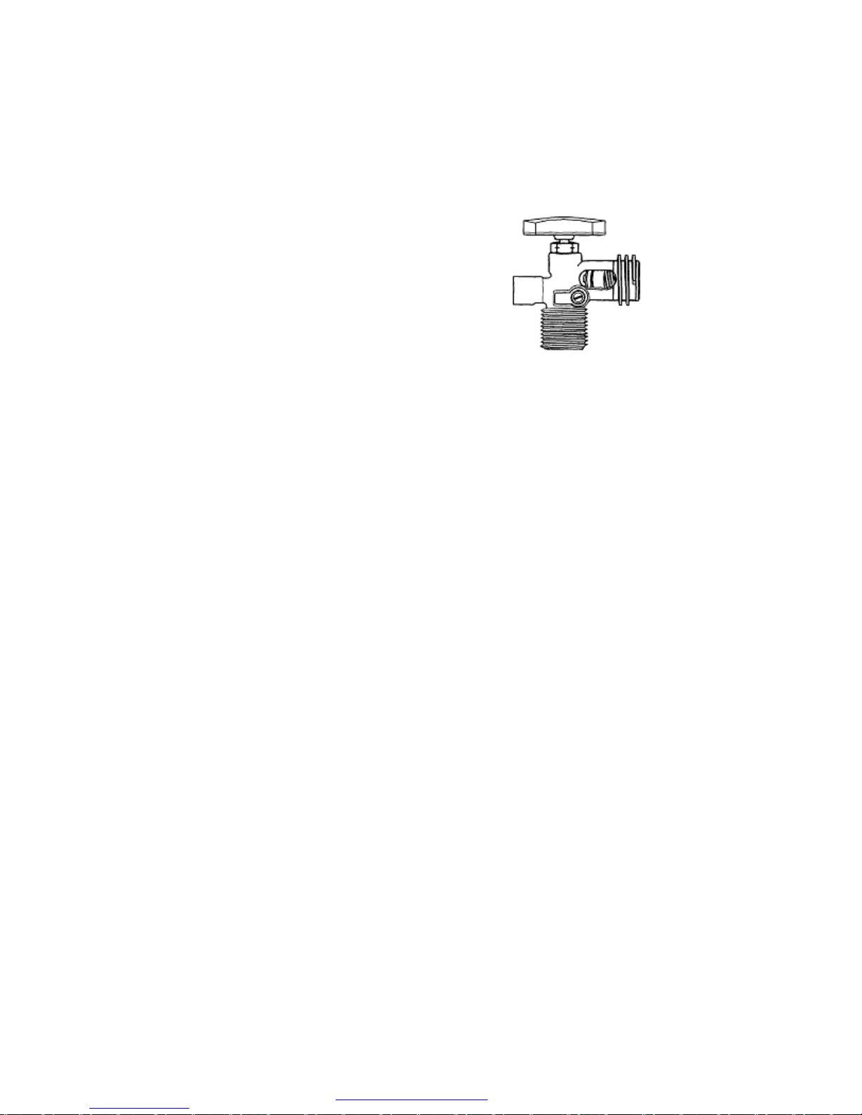
2. A small screw on the side of main body
OPD Cylinder Valve
referred to as the 10 % valve which allows
air to be released and indicates when
container is at 80 % capacity.
3. Incoming positive seal valve MUST be
pushed inward with fill nozzle to fill or by
POL fitting to draw vapor out for appliance
use.
On the bottom side is the float which closes
when 80 % of capacity has been reached.
This permits expansion space in the tank when temperature rises.
See section on main hoses.
At any point a container is disconnected, BE SURE to install the
dust cap or plug over entry (if so equipped).
Whenever the container is detached from the propane system , DO
NOT allow the cylinder to move or roll around during transportation
to and from the gas supplier.
Servicing and Filling Propane Containers
Filling a propane container must be done carefully and correctly.
Only a qualified person, properly trained on inspection, filling and
safety procedures, should fill container.
To remove the propane containers for refilling.
1. Remove the bottle covers ( if used ).
2. Close the main valve on the container.
3. Remove the two hoses from the ACME connection.
4. Install the rubber cap over the valve - ACME connection. (if so
equipped)
5. Remove/loosen the wing nut holding the clamp hook.
6. Remove the clamp hook.
7. Fill the bottle and reverse the procedure to install. Test all
connections for leakage.
A new container MUST be “purged” before placing into service and
MUST NEVER BE OVERFILLED. Purging is an operation
performed by your dealer or propane agency to remove any
atmospheric air. As an owner you need not be concerned regarding
this procedure unless you permit the valve to be in OPEN position
when empty.
Two overfill devices are built into the valve to prevent overfilling of
55
PDF created with pdfFactory trial version www.pdffactory.com
Page 63

the container. First, is the small brass “knob” or “screw” inside of the
valve. This “10% valve” must be open when filling, allowing air to
escape. When the container reaches 80% of the correct capacity,
liquid appears. Shut the supply filling valve off. Close the 10%
valve plus the top handle of the main valve.
When refilling propane containers, they are generally removed from
propane compartment or tie downs. BE SURE to reinstall correctly,
as shown in installation instructions, and test for leaks.
When propane containers are filled to 80% level there is available
space for safe expansion of the vaporized liquid. Should your
container become slightly overfilled, pressure may rise due to hot
sun.
It could cause the overflow valve to “blow-off” and emit a small
quantity of propane vapor. This can be detected by a strong odor
around tanks. Keep open flames away from this area. It is best to
remove the bottle, take it to a safe area, and “bleed-off” the excess
pressure by opening the valve slightly and closing it when discharge
has been sufficient, one to two minutes.
When disconnecting propane containers, you must turn the acme
fitting in a clockwise direction because left-hand threads are utilized.
When reconnecting, turn connections counterclockwise.
Connections must be tight, however DO NOT over-tighten.
!
Your vehicle has exterior combustion air inlets. Appliance pilot lights should be turned off
during gasoline or propane refueling. (Required by law in some states.)
Installing Propane Containers
Venture recreational vehicles are equipped with 20 or 30 pound
propane containers, depending on floor plan models.
Mounting and attaching instructions are listed below:
1. Thread the long rod into the base plate.
2. Set both bottles into place as shown.
3. Drop the double hook bracket over the rod and hook onto the
bottle.
4. Attach the wing-nut to hold the bracket and tighten to hold the
bottle to the plate.
5. Attach the regulator with the vent down to the bracket.
WARNING
56
PDF created with pdfFactory trial version www.pdffactory.com
Page 64

6. Attach the main hose from the regulator to the manifold fitting in
the frame.
7. Attach two short pigtail hoses to the regulator and bottles at the
ACME fitting.
8. Test all propane connections for leakage.
A warning label has been located near the propane container. This
label read as follows:
DANGER
!
All pilot lights, appliances and their igniters (see operating instructions) shall
be turn OFF before refueling of motor fuel tanks and/or propane containers.
FAILURE TO COMPLY COULD RESULT IN DEATH OR SERIOUS INJURY.
WARNING
!
A warning label has been located near the propane container. This label
reads as follows:
DO NOT FILL CONTAINER(S) TO MORE THAN 80 PER-
CENT OF CAPACITY.
1. Overfilling the propane container can result in uncon-
trolled gas flow, which can cause fire or explosion.
2. A properly filled container will contain approximately
80 percent of its volume as propane.
!
Never smoke during the filling of propane tanks. Keep the recreational vehicle away from immediate filling area when possible or extinguish all gas
pilots.
CAUTION
DO NOT use tools to open or close the tank valve. HAND TIGHTEN ONLY to
avoid damage to the valve or handle.
PDF created with pdfFactory trial version www.pdffactory.com
!
WARNING
57
Page 65

!
Propane cylinders shall not be placed or stored inside the vehicle. Propane
cylinders are equipped with safety devices that relieve excessive pressure
by discharging gas to the atmosphere.
FAILURE TO COMPLY COULD RESULT IN DEATH OR SERIOUS INJURY.
WARNING
CAUTION
THIS GAS PIPING SYSTEM IS DESIGNED FOR USE WITH PROPANE ONLY.
DO NOT CONNECT NATURAL GAS TO THIS SYSTEM.
Securely cap inlet when not connected for use. After turning on gas, except
after normal cylinder replacement, test gas piping and connections to appliances for leakage with soapy water or bubble solution. Do not use products
that contain ammonia or chlorine.
Regulator
Regulators that are not in compartments have been equipped with
a protective cover. Make sure that the regulator vent faces
downward and that the cover is kept in place to minimize vent
blockage that could result in regulator failure to operate
The regulator has the only moving components in the propane
system. It’s sole function is to reduce the high and varied pressure
from the propane containers to safe and consistent low operating
pressure. The small inlet is the first stage, which reduces the
container pressure to 10-13 pounds.
The second stage then reduces the 10-13 pound pressure to an
operating pressure of 11 inches w.c. (water column) or 6.35 ounces
of outlet pressure to your appliances. The second stage is
adjustable and may need to be adjusted for precise operation. We
suggest this to be normal maintenance and performed once per
year. Do not make this adjustment without a manometer. This
instrument is required to read actual pressure.
If pressure is too high, it affects performance and safety. Should
pressure be too low, appliances will not operate correctly. An
!
58
PDF created with pdfFactory trial version www.pdffactory.com
Page 66
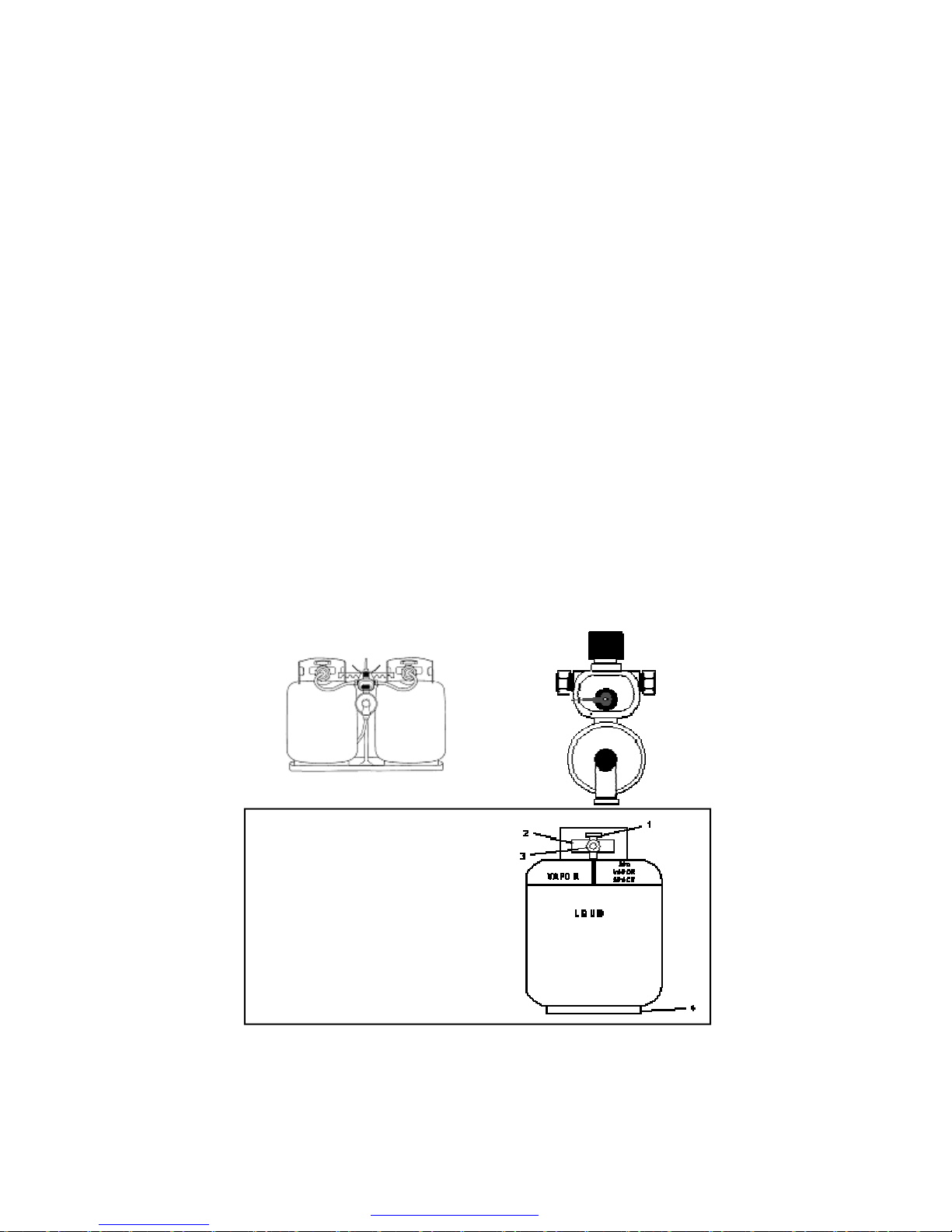
authorized technician with proper equipment should perform such
tests and adjustments, as may be required.
The propane regulator used on the Venture units, is the automatic
two stage regulator. With both cylinders full of propane, turn the
lever on the regulator towards the cylinder you wish to use first.
This will now be the “supply” cylinder and the other “reserve”.
Slowly open both cylinder valves.
The “ Supply” side of the regulator will continue to supply propane
as long as sufficient propane remains in the “Supply” cylinder. When
pressure in the cylinder drops to about 10 psig, the “reserve” side of
the regulator will open and continue to regulate at 11” WC. At the
time the “supply” cylinder becomes exhausted, a red warning flag
appears in the indicator window. This red or orange flag indicates
that a cylinder exchange can be made.
Before removing the empty cylinder, close the valve to prevent air
from entering to cylinder.
After filling the cylinder, connect the pigtail hose and slowly open the
bottle valve. Do not forget to check for leakage each time you refill
cylinder or disconnect any part on the
propane system.
1. Knob to open and close main valve.
2. Complete valve assembly.
3. “10% valve“, (small brass knob or
slot screw).
4. Container mounting stand.
59
PDF created with pdfFactory trial version www.pdffactory.com
Page 67
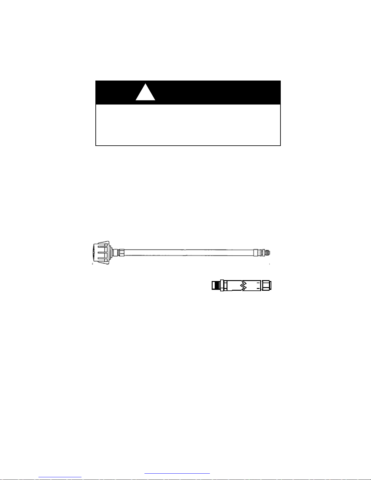
CAUTION
!
If you have double bottles and a standard regulator on your RV, use only
one bottle at a time. Otherwise the gas supply will be drawn equally from
both bottles until supply has been totally exhausted. Using one bottle until
it is empty, then using the second bottle will allow you to fill the empty
bottle at your convenience without being totally out of propane.
High Pressure Hoses with Acme Connectors
Propane leaves the container through a hose with an ACME
connector attached to the bottle, also having a “flow-limiting device”
designed to sense excessive flow. Two functions of this device: 1.
should the container valve be opened too quickly this device may
close, stopping the flow of propane. 2. Should there be a rupture in
propane line, it will reduce the flow to a maximum of 10 (SCFH)
Standard Cubic feet per Hour.
This device will equalize normal flow in about 5 seconds, generally
not noticeable.
Main Supply Hose – Low Pressure
The main supply hose will be attached
from the regulator to the brass manifold
fitting in the frame of the coach. The
swivel brass nut on the main hose will be your final attachment.
There are several things to remember each time the container is
removed:
1. Be sure ALL fittings are tight. Always use two OPEN END
wrenches for brass connections.
2. Be sure ALL connections are tested for leakage.
3. Open the main valve slowly to avoid a fast rush of propane to
flow-limiting device causing propane “freeze”.
4. Listen carefully – a “hissing” sound longer than one second may
indicate a propane leak. Close valve and search for leak.
60
3/8” MPT x 1/2” Female
Flare Swivel
PDF created with pdfFactory trial version www.pdffactory.com
Page 68

Should you experience a propane “freeze-up”, close the main valve
and wait 15 minutes before trying again. Keep the container valve(s)
closed when traveling. Some states prohibit traveling with the
propane container valves open, especially in underground tunnels on
expressways.
Operation
After the camper is completely set up and you are prepared for
camping enjoyment, follow these steps for propane operation.
1. Be sure ALL burner valves, controls, and pilot light valves are
closed.
2. Open main valve on propane container slowly to avoid a fast rush
through excess flow valve causing “propane freeze”.
3. Listen carefully as propane begins to flow. If a “hissing” sound is
heard for more than one or two seconds, close valve and search
for a potential leak.
4. Light appliances as needed and directed in Chapter Five Appliances.
Checking for Leaks
The entire propane distribution system and appliances have gone
through complete factory and dealer tests for any leakage. When
traveling with your RV, normal vibrations and road movement may
cause connections to loosen and develop leaks.
For normal maintenance we advise all owners to test for leakage at
least once per year or more often. You may request your dealer to
perform a maintenance check each spring.
Should you encounter an odor, possibly propane, turn off any and all
open flames and begin a systematic search for leaks on the complete
propane system. NEVER USE A MATCH. Use a soapy water
solution which contains NO AMMONIA, or CHLORINE content to
check for leaks. If a leak is identified, bubbles will appear. ALWAYS
use two wrenches when tightening brass connections to prevent
twisting of copper.
For your own protection, the following warning label has been placed
near the cooking area to remind you of the need of oxygen for
combustion and breathing. Due to smaller area in your recreational
vehicle, there is less oxygen than in your home. Proper ventilation is
required when cooking.
61
PDF created with pdfFactory trial version www.pdffactory.com
Page 69

DANGER
!
IT IS NOT SAFE TO USE COOKING APPLIANCES FOR COMFORT HEATING. Cooking appliances need fresh air for safe operation.
Before operation:
1. Open overhead vent or turn on exhaust fan.
2. Open window (s).
FAILURE TO COMPLY COULD RESULT IN DEATH OR SERIOUS INJURY.
Unlike homes, the amount of oxygen supply is limited due to the size of the
recreational vehicle, and proper ventilation when using the cooking appliances avoids danger of asphyxiation. It is especially important that cook-
ing appliances not be used for comfort heating, as the danger of asphyxia-
tion is greater when the appliance is used for long periods of time.
It is especially important that cooking appliances not be used for
comfort heating, as the danger of asphyxiation and unsafe
levels of carbon monoxide are greater when the appliance is used
for long periods of time.
Propane Consumption
All your propane appliances are operated intermittently. Your
furnace is naturally the appliance using the most fuel, especially if
freezing conditions are present outside. On a very cold and windy
day it is conceivable that your coach could consume most of a 30
pound propane bottle.
Propane consumption depends mostly upon individual use of
appliances and the length of time operated. Each gallon of propane
produces about 91,500 BTUs of heat energy. Following is a list of
typical appliance consumption when turned on fully for one hour of
operation:
62
PDF created with pdfFactory trial version www.pdffactory.com
Page 70
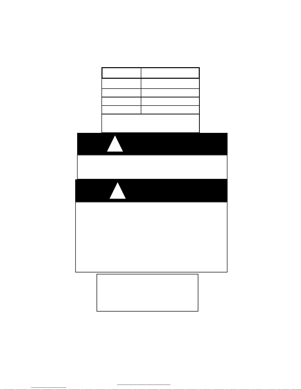
APPLIANCE LP GAS CONSUMPTION
Water Heater 12,000 BTU
Furnace 20,000- BTU
Stove/Oven 6,500-9,100 BTU
Refer 1,200-2,200 BTU
Note: The above chart represents many
different models.
!
Portable fuel-burning equipment, including wood and charcoal grills and
stoves, shall not be used inside the recreational vehicle. The use of this
equipment inside the recreational vehicle may cause fire or asphyxiation.
DANGER
1. Extinguish any open flames, pilot lights, and all smoking materials.
2. Do not touch electrical switches.
3. Shut off the propane supply at the tank valve(s) or propane supply connection.
4. Open doors and other ventilating openings.
5. Leave area until the odor clears.
6. Have the propane system checked and leakage source corrected
before using again.
FAILURE TO COMPLY COULD RESULT IN EXPLOSION RE-
SULTING IN DEATH OR SERIOUS INJURY.
ALL GAS LINES HAVE BEEN CHECKED
WITH AIR PRESSURE. DEALERS ARE
REQUIRED TO RECHECK BEFORE DE-
!
If You Smell Propane:
LIVERY TO RETAIL CUSTOMERS.
WARNING
63
PDF created with pdfFactory trial version www.pdffactory.com
Page 71
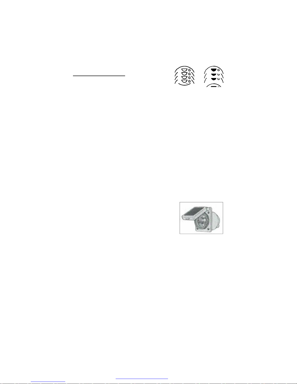
ELECTRICAL SYSTEM
General Information
30-A, 125-V, 2-pole, 3-wire,
grounding type
The electrical system in your recreational vehicle is designed for using
both 120 volt AC (alternating current) and 12 volt DC (direct current)
capabilities. All installations and designs are built to comply with
safety requirements of ANSI standard 1192, National Electric Code
and Canadian Standards Association.
This model manufactured by VENTURE RV has 30 amp system.
Highly recommend that your RV electrical connection, is not
plugged into a household outlet.
Changes and Modifications
Any changes, alternations, additions, and/or modifications need to be
performed by qualified electrical technicians, using only approved
components which meet safety and code requirements. This includes
owners, dealers, etc. who desire to make changes. The manufacturer
is not responsible for any changes, or alterations, made to the 120
AC system of the coach.
120-Volt A/C System
Power Cord 30 AMP
The 30 amp rated power cord is not pre-wired into the breaker box.
Open the hatch door as shown, on the exterior of the coach. Pull cord
out from interior storage and attach it to incoming 120-volt power
source and your RV.
This cord places 120 AC volt power into your breaker distribution
center, as built into your coach, also rated at 30 amps.
Energy will enter through the main breaker and is distributed through
circuit breakers to the wall receptacles and appliances. This power
cord will be approximately 26 to 28 feet in length. Each cord has the
correct gauge of wire to carry the correct voltage to the coach.
64
PDF created with pdfFactory trial version www.pdffactory.com
Page 72
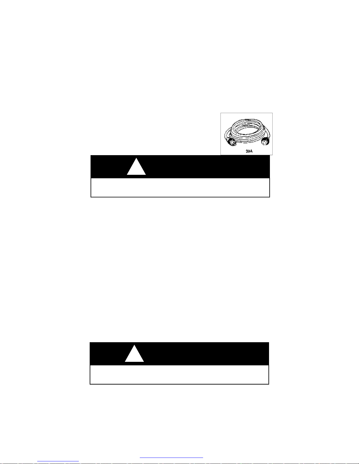
In some hook-ups the power cord may not be long enough and
extension cords are required. Always use a cord with the gauge of
wire equal to or greater then the power cord. Should you use a cord
with a smaller wire gauge, overheating, loss of amperage, and
possible melting could occur.
DO NOT leave any unused portion of an
extension cord in a “coil” as it may overheat,
short-circuit wires and potentially destroy your
extension cord.
WARNING
!
Never use a “cheater” plug or extension cord which breaks the continuity of
the ground circuit to the grounding pin.
Circuit Breakers and Box—120 VAC
On a 30 amp system, a maximum of six distribution circuits are
permitted. All breakers are sized according to power needs on each
line.
The following generic drawing shows the circuit breaker alignment
with number one being the main breaker on all floor plans.
Depending on the size, floor plan and options of your coach, circuit
three through six will vary and possibly not all circuits will be used.
Number two is generally the 20 amp air conditioner circuit.
An owner must realize and understand that a coach has a total of 30
amp service available to be used. Conserving and choosing which
appliance has priority in consumption needs to be part of the
planning.
Don’t forget loose items such as toasters, electric skillets, and coffee
pots also consume power. Include these also in your planning.
WARNING
!
Do not replace breakers or fuses with any that are rated at a higher
amperage. Over fusing may cause a fire by overheating the wire.
65
PDF created with pdfFactory trial version www.pdffactory.com
Page 73
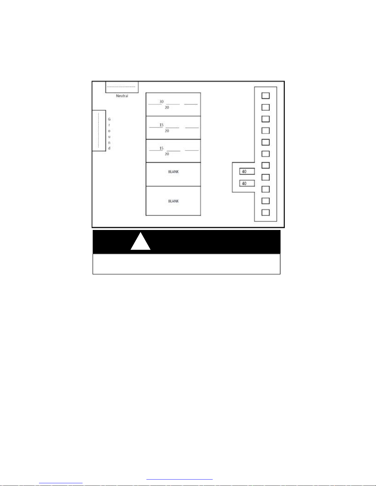
WARNING
!
NEVER, under any circumstances, remove a grounding pin in any cord or
plug. It may mean the difference between LIFE OR DEATH.
GFCI Protection
Each coach has a GFCI, Ground Fault Circuit Interrupter, protection
receptacle installed into the circuitry. This GFCI device is designed to
protect people from hazards of line to ground electric shock. The
purpose is to reduce possible injury caused by electrical shock,
resulting from faulty insulation and/or installation, improper polarity
and related to moisture and/or earth ground.
The third “round” pin on the receptacle is very important for this safety
device to function correctly. NEVER cut off this pin. When using an
appliance in the receptacle without this provision, use an adapter with
a pigtail adapter to be attached to the receptacle box to complete the
circuit.
66
PDF created with pdfFactory trial version www.pdffactory.com
Page 74

This GFCI receptacle will not protect against short-circuits or
overloads. The circuit breaker or fuse in the electrical panel which
supplies power to the circuit provides this protection.
Polarity is extremely important. You should be certain that the
polarity of the external power is not reversed, in order to avoid harm
to appliances and personal electrical shock. Polarity testers may be
purchased in most electrical and hardware stores with the GFCI
tester built in.
During use of the recreational vehicle it is suggested to test this
receptacle once per month. To test, press the “TEST” button in.
The “RESET” button should pop out. Power should now be turned
off at this receptacle and any receptacles down line. To restore
power push, then release the “RESET” button.
12-Volt DC System
Most interior lights and appliances receive 12-volt DC power through
converter output and/or the auxiliary battery. Exterior lights and
brakes also use 12-volt DC power from the tow vehicle battery and/
or auxiliary battery through the seven way connecter and wire
attached to the tow vehicle. Following are explanations of various
items.
Converter
The heart of your 12 volt DC system is enclosed inside of the load
center, including 12V fuse panel, 120VAC breaker panel, and
converter.
.
Fuse panel may have numerous fuse positions, depending on output
size of your converter.
All converters have solid state electronic components internally to
produce “clean” 12V DC power.
This load center will have a brown plastic front with a small door to
access fuses and breakers.
The function of a converter takes 120-volt AC power and transforms
this energy into 12-volt DC power as used in your coach. 12-volt DC
supplies power for some appliances and most interior lights. The
floor plan and size of coach indicate the output size.
67
PDF created with pdfFactory trial version www.pdffactory.com
Page 75

When the converter receives 120 AC power, it transfers power into
12-volt DC without any manual switches. The converter also
charges the auxiliary battery (s) when installed on the coach and is
attached to 120-volt AC power. The third function of a converter is
to send 12-volt power to the fuse panel and throughout the coach.
Each converter has a “built-in” fan which operates through a load
sensor control or temperature sensor. As more current is drawn, fan
will speed up, run faster, or slow down, based on amp draw and/or
temperature. Should the fan not run at all, the converter may
overheat and will cut-out and/or stop.
Auxiliary Battery —NOT OEM available
All travel trailers and fifth wheels are pre-built to accept a battery.
Batteries are not standard equipment on units.
Recommended batteries are of deep-cycle type as you need longer,
slow consuming power rather than cold-cranking power. A battery is
always required for a break-away switch to function.
A battery requires routine maintenance for long life. First, terminals
need to be kept clean to avoid corrosion. Second, a battery used
daily will consume water as long as the converter is in operation. Be
sure to check the battery no less than every 30 days and keep the
battery filled with distilled (rain) water. Most good deep cycle
batteries are NOT maintenance free.
A converter will not overcharge a battery unless a battery has a
dead cell, or the converter has a malfunction. Some type of
converters have full battery charge shut-off. Other types reduce the
rate of charge as battery conditions reach 12.7 volts DC or 1.265
specific gravity at 80°F. By electronic standards, a battery is
discharged at 10.5 volts. Dropping voltage lower than 10.5 volts will
begin damaging plates in the battery.
The interior lights will operate from the converter and/or auxiliary
battery. Some lights will have wall switches and other lights have
switches in the lights themselves.
Circuit Breakers and Fuses—12 Volt DC
These two items have been installed in your coach to protect
circuitry and components:
68
PDF created with pdfFactory trial version www.pdffactory.com
Page 76
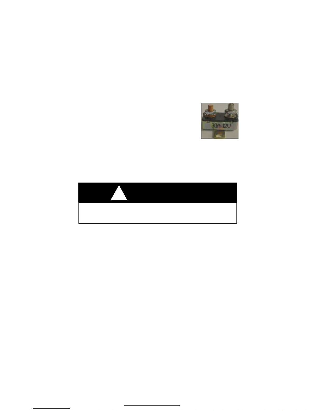
Fuses are placed into the fuse panel with the converter or into a
separate panel near the converter with access inside of coach.
Fuses are placed in your electrical system to protect wiring and
components when overloads appear or short circuits occur. Radios,
stereos and possibly other components may have “in-line” fuses
attached to their own wire harness.
Circuit breakers are placed at several locations. An
automatic reset breaker is placed within 18 inches
of the auxiliary battery. Breaker will automatically
reset upon “cool down”, normally 60 seconds.
Two 40 amp or four 20 amp fuses are placed in the converter to
protect circuitry should you hook-up a battery backwards. Fuse will
blow instead of converter.
A 30 amp automatic reset breaker is installed in the load center to
operate your slide-out( s).
WARNING
!
DO NOT replace circuit breakers or fuses with a higher current rating than those
supplied with your coach. Over-fusing can cause a fire hazard by overheating the
electrical wiring.
All wiring used in your coach meets correct amp rating correlated
with fuses and breakers in respective panels as required by code.
The RV battery is placed in parallel circuitry with the battery on your
tow vehicle. Care needs to be exercised not to drain both batteries
together. There are two methods of avoiding this condition:
First, disconnect the tow vehicle when parked and/or using your
coach.
Second, a battery isolator may be installed in your tow vehicle to
prevent power drain from batteries in both vehicles. This device
“isolator” has two useful purposes. First, it sends current from the
alternator to both batteries simultaneously. Secondly, the isolator
prevents draw from the recreational vehicle through the battery of
the tow vehicle, preserving power to start the engine.
69
PDF created with pdfFactory trial version www.pdffactory.com
Page 77
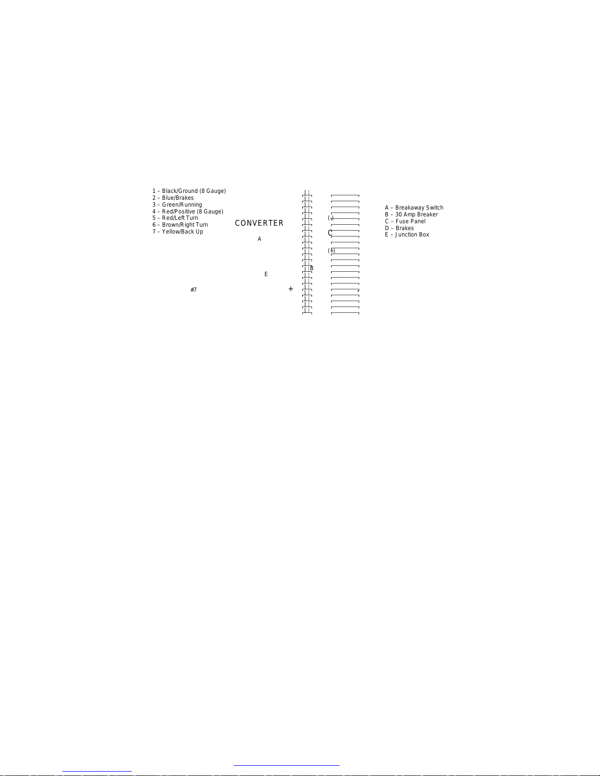
Contact your dealer should you desire an isolator for your protection.
Two types are available, mechanical type, or solid state which is the
best and most expensive.
#1 – Black/Ground (8 Gauge)
#2 – Blue/Brakes
#3 – Green/Running
#4 – Red/Positive (8 Gauge)
#5 – Red/Left Turn
#6 – Brown/Right Turn
#7 – Yellow/Back Up
D
#2
#6
#4
#7
#5
#3
CONVERTER
#1
(-)
A
E
+
C
(+)
B
AUXILIARY
BATTERY
-
A – Breakaway Switch
B – 30 Amp Breaker
C – Fuse Panel
D – Brakes
E – Junction Box
Exterior Lights and Connector, 12 Volt
Power for exterior lights, such as tail lights, turn, clearance and
brake lights, is supplied by the tow vehicle.
Note the diagram (above) showing the color code and numbers from
the seven way connector and how power is fed to the exterior lights.
The positive red wire is attached to the battery to transfer power to
the coach.
The connector between the recreational vehicle and the tow vehicle
may build up corrosion due to moisture. You may need to clean
these terminals occasionally to insure good electrical contact.
Porch Lights
Porch lights are placed on sidewalls, left and right side. Switches for
these lights, depending on models, will be in the interior, right ( door
side ) side wall. Occasionally, the switch will be on the light itself.
Brake Wiring
The 10 inch electric brakes operate on 12-volt power supplied from
the tow vehicle, transferred through the blue-positive and whitenegative in the seven way harness. There are no fuses or breakers
installed in this brake wiring. More information on the brake system
is found in Chapter Three - Using Your RV.
70
PDF created with pdfFactory trial version www.pdffactory.com
Page 78
If experiencing any electrical problems, check the following items,
fuses, breakers, and connections. If none of these items resolve the
problem, contact your dealer for trouble shooting, and needed
repairs.
FURRION is a solar panel connection, for portable panel,
placed in sun light, on the ground or a table. Only the hook-up
connection has been installed in this RV.
Charging your auxiliary battery is it’s main function.
The actual solar panel is an after market item and not available from
or thru manufacture of this RV.
You would use this system only when 120 VAC is not available.
CAUTION
!
Any electrical installation that does not meet the criteria of the
manufacturer’s specification will VOID THE WARRANTY on the electrical
system.
71
PDF created with pdfFactory trial version www.pdffactory.com
Page 79
CHAPTER 5
APPLIANCES
VENTURE RV places brand name, quality-built equipment, as
guided by current codes and standards, in all recreational vehicles.
Some appliances are built and equipped to operate on propane gas
ONLY. DO NOT attempt to operate on natural, butane or methane
gas.
Each appliance has its own specific manual, written and published
by its manufacturer. These manuals supply additional information
about the appliances in your recreational vehicle.
SAFETY——READ BEFORE OPERATING
The first four appliances in this chapter, all use propane for their
MAIN source of fuel, plus some use 12 volt DC and 120 volt AC
energy also . Chapter 4 has more information on propane .
IT IS VERY IMPORTANT THAT YOU AS AN OWNER AND
OPERATOR ARE FULLY AWARE WHAT PROPANE ODOR IS OR
SMELLS LIKE, FOR YOUR PROTECTION.
DANGER
!
What to do if you smell Propane.
This section involves all appliances which use and consume propane, may or may not have a pilot light.
1. Extinguish any open flame.
2. Evacuate all persons from vehicle.
3. Shut off the propane supply at container.
4. DO NOT start any engine or generator.
5. DO NOT touch any switch, phone, or radio in vehicle.
6. Contact the nearest propane supplier, service technician, or fire
department personnel.
7. DO NOT turn propane supply on until problem or leak has
been solved.
FAILURE TO COMPLY COULD RESULT IN
SERIOUS INJURY, EXPLOSION, OR DEATH.
72
PDF created with pdfFactory trial version www.pdffactory.com
Page 80
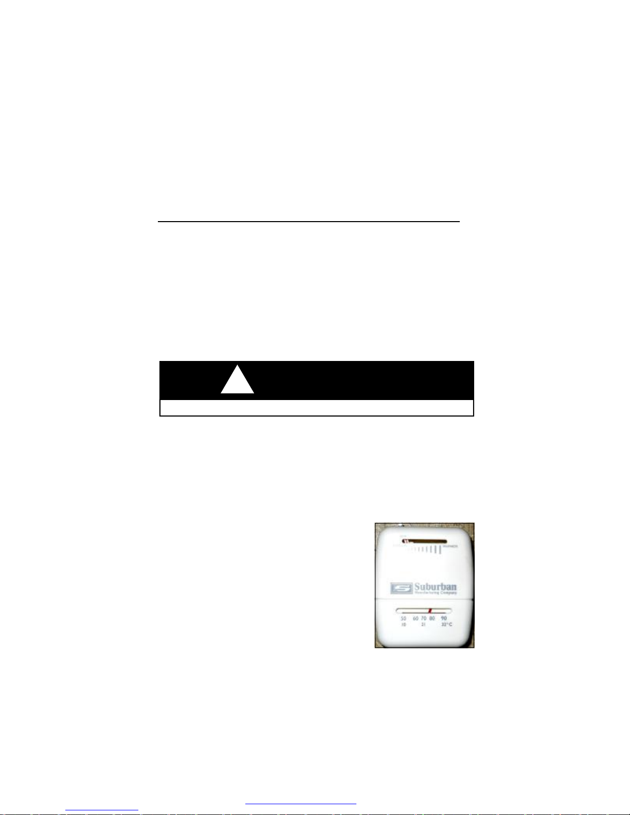
BEFORE OPERATING, take note of any unusual odor in coach,
near floor or elsewhere similar to propane.
Each appliance has it’s own manual, be sure to read and obey all
instructions as written by manufacture.
FURNACE____________________________________________
The furnace in your recreational vehicle requires 12-volt DC
electrical current and propane gas energy for correct operation. The
furnace receives 12-volt DC power from a fully charged battery and/
or the converter in the coach. This power must be present before
propane gas can enter through the control to the burner tube.
The combustion chamber is completely sealed to prevent any
carbon monoxide from entering into the coach. Oxygen is drawn into
the chamber through the upper vent and exhaust fumes expelled
through the lower vent.
!
DO NOT operate furnace while vehicle is in motion or being towed.
The basic operation of furnace is performed by thermostat mounted
on interior wall of your coach.
THERMOSTAT
Has an on/off switch and temperature setting on top.
From the time you turn the thermostat on,
there is a delay built into the furnace to form a
purge cycle, preventing any possible propane
vapor buildup in the chamber of the furnace.
NOTE; Different model furnaces are used
for different unit floor plans. Each model
furnace has it’s own Users Manual. The
following instructions may vary slightly from
the instructions in your unit. Therefore, refer
to the users manual provided in your unit
WARNING
73
PDF created with pdfFactory trial version www.pdffactory.com
Page 81

Operating Instructions
1. Before using your furnace, it is suggested to open entrance door
and windows to ventilate camper for any unusual odors such as
propane or other.
2. Be sure propane container has fuel and valve is turned open.
3. Release thermostat from OFF position .
4. Set thermostat to 5 to 8 degrees above room temperature.
5. Blower will start in 0 to 15 seconds, run for 30 seconds during
heat chamber PURGE cycle, to remove any propane vapor from
chamber.
6. Second cycle, blower continues to run, module board will; (a)
send spark to the burner tube; (b) open valve to release propane to
the burner tube.
7. Ignition attempt will be for 7 seconds.
8. Failing to ignite, board will make 2 more attempts to light the
burner and then go to lock-out.
9. If after (3) attempts with no ignition, drop thermostat to lowest
setting, wait 1 minute and repeat the same steps, 3 to 9.
10. After burner lights, set thermostat at desired at desired setting.
11. To shut burner down, move thermostat to lowest setting or OFF.
12. Blower will continue to run for about 2 minutes until heat is
removed from chamber.
This furnace is equipped with a 12 volt shut-off switch. With switch
turned “OFF”, furnace will NOT operate, propane will not flow to
burner nor will furnace operate. To locate this switch, a cabinet
panel may need to be removed.
NOTE; During initial firing of this furnace, a burn-off of excess paint
and oils remaining from manufacturing process may cause
“smoking” for five to ten minutes. Your dealer may have already
performed a “burn-off”.
WARNING
!
If you do not follow these instructions exactly, a fire or explosion may result
causing property damage, personal injury or loss of life.
A. Use only your hand to turn the handle on the manual shut off
valve. Never use tools. If the handle will not turn by hand,
don’t try to repair it, call a qualified service technician. Force
or attempted repair may result in a fire or explosion.
74
PDF created with pdfFactory trial version www.pdffactory.com
Page 82

B. Do not use this appliance if any part has been under water.
Immediately call a qualified service technician to inspect the
appliance and to replace any part of the control system and
any gas control which has been under water.
WARNING
!
Do not install screens over the vents for any reason. Screens will become
restricted and cause unsafe furnace operation. Accessories are being marketed for RV products which Venture RV does not recommend. For your
safety, only factory authorized parts are to be used on your furnace.
External Vents. Always be sure these vents are clear of any
objects like screens, duct tape, etc.
Ducting. This furnace is called a “BLOW THRU “ system and
no duct work is used. Any restrictions in front of grill, will prevent the
furnace from correct operation. Never block grill off completely,
possibly causing furnace to limit out and shut down.
Propane pressure, as defined in Chapter Four - Systems, is
extremely important. A dial gauge or U-tube manometer is required
to perform tests and adjustments. Pressure must be set at 11
inches w c. (water column) plus or minus 1/2 inch. Incorrect gas
pressure can cause any appliance to operate inconsistently and
cause poor combustion. Only qualified technicians with proper
equipment should make any mechanical adjustments.
Voltage must be between 10.5 volts to 13.5 volts at the furnace
during operation. Below 10.5 volts the furnace will shut down. Both
high and low voltage places excessive wear on the motor and
brushes.
Any mechanical adjustments, such as electrode adjustments,
should be performed by a qualified service technician
75
PDF created with pdfFactory trial version www.pdffactory.com
Page 83

DROP-IN COOK TOP
The cooking appliance used in the Venture RV, Sonic models, is a 2
Burner Drop-In Cook top. These appliances operate with propane
gas only, never natural gas or methane. This model of stove DOES
NOT have a free standing pilot light.
OPERATING INSTRUCTIONS
1. Know which knob controls which burner. Always be sure the
correct burner is turned on.
2. Depress knob and turn fully counter-clockwise to “Lite” position.
a. Verify sufficient propane supply before attempting to light
burner. Air in the gas line will significantly delay burner
ignition. The burner may light unexpectedly as the air in
the lines clears and is replaced by propane. This
unexpected ignition could burn you. Air in the gas lines
may occur after the vehicle gas bottle and/or tank is
refilled, during and after servicing other appliances on
same propane line, etc.
b. Do not attempt to light more then one burner at a time.
c. Immediately light burner by holding a long match near the
burner ports.
3. If any burner should extinguish after initial lighting or due to
accidental blow-out, turn propane off by turning control knob
clockwise to “OFF”, wait five (5) minutes before attempting to
relight the burner. Failure to follow these instructions could result
in a fire or explosion.
If the burner should go out while cooking, or if there is an odor of
propane, turn control knob (s) clockwise to ’OFF’. Wait five (5)
minutes for propane odor to disappear. If propane odor is still
present—Do not relight burners, See “What To Do If You Smell
propane ” on the front cover of the Cook Top manual.
4. To turn burner( s) “OFF”, turn the appropriate control knob
clockwise to ”OFF”.
DANGER
If the information in this manual is not followed exactly, a fire or explosion
may result causing property damage, personal injury or death.
PDF created with pdfFactory trial version www.pdffactory.com
!
76
Page 84

CAUTION
Hand held igniters may be used but be sure they are the type designed for
lighting open flame burners.
!
!
Be sure all control knobs are turned “OFF” when you are not cooking.
Someone could be burned or a fire could start if a burner is accidentally
left on or unattended even if only momentarily.
!
If the user of this appliance fails to maintain it in the condition in which it
was shipped from the factory or if the appliance is not used solely for its
intended purpose or if appliance is not maintained in accordance with the
instructions in this manual, then the risk of a fire and/or the production of
carbon monoxide exists which can cause personal injury, property damage
or loss of life.
DANGER
ALL PILOT LIGHTS, APPLIANCES AND THEIR IGNITORS (SEE OPERATING IN-
STRUCTIONS) SHALL BE TURNED OFF BEFORE REFUELING OF MOTOR FUEL
TANKS AND/OR POPANE CONTAINERS. FAILURE TO COMPLY COULD RESULT
!
IN DEATH OR SERIOUS INJURY.
WARNING
WARNING
!
DO NOT OPERATE THIS APPLIANCE UNLESS THE PRIVACY CURTAIN IS SE-
CURED. FAILURE TO COMPLY COULD RESULT IN FIRE OR SERIOUS INJURY.
PDF created with pdfFactory trial version www.pdffactory.com
WARNING
77
Page 85

WATER HEATER________________________________________
SAFETY INFORMATION
FOR YOUR SAFETY READ SAFETY INSTRUCTIONS ON
PAGE 73.
OPERATING INSTRUCTIONS—GAS
A. This appliance does not have a pilot light. It is equipped with an
ignition device which automatically lights the burner. Do not try
to light the burner by hand.
B. This is an automatic propane valve, no adjustments are
necessary. Do not attempt to repair the propane valve. This
may result in a fire or explosion.
C. Do not use this appliance if any part has been under water.
Immediately call a qualified service technician to inspect the
appliance and to replace any part of the control system and any
gas control which has been under water.
D Before operating water heater, check the location of the vent to
make sure it will not be blocked by the opening of any door on
the trailer. If it can be blocked, do not operate the water heater
with the door open.
OPERATING INSTRUCTIONS FOR UNITS WITH DIRECT SPARK
IGNITION GAS VALVE.
1. STOP! Read the safety information provided.
2. Turn off all electric power to the appliance.
3. Turn “OFF” propane supply.
4. Wait five minutes for propane to clear the area. If you smell
propane, then STOP! Follow instructions in item B of the safety
information. If you do not smell propane, go to the next step.
5. Turn “ON” the propane supply.
6. Turn on water heater appliance at monitor panel for propane
operation.
7. Turn switch marked “GAS”, which is located on the bottom of the
monitor panel, to “ON’ position. If the burner does not light, the
system will automatically attempt two more tries for ignition
before lock out. NOTE: Each ignition cycle will have a fifteen
second purge before spark cycle if the system is a three try
system.
78
PDF created with pdfFactory trial version www.pdffactory.com
Page 86
8. If lock-out occurs before main burner lights, turn switch to “OFF”,
wait five seconds and turn switch to “ON” position. This will
restart the ignition cycle. The first start-up of the heater may
require several ignition cycles before all air is purged from the
propane lines.
If the burner will not come on, the following items should be checked
before calling a service person:
1. Switch turned off.
2. Propane supply to heater is empty or turned off.
3. Reset button on ECO is tripped.
4. If burner fails to light, call a Suburban Service Center or a local
RV service agency.
OPERATING INSTRUCTIONS—ELECTRIC ELEMENTS
Electric water heaters are designed to operate with a minimum
amount of service problems, however, proper operation and care is
essential.
By far the most common trouble with electric water heaters results
from energizing the water heater before it is filled with water. Even
brief operation of the electric element without water in the tank will
burn out the electric heating element as soon as 30 seconds.
Before the electric element will operate, the switch located behind
the water heater door in the lower left corner of the control housing
must be in the “ON” position.
To energize the electric element, locate the switch, which is on the
bottom of the monitor panel, inside the RV and turn the switch
marked “ELECTRIC” to the “ON” position. The water heater
temperature will be regulated by the thermostat.
WARNING
It is imperative that the water heater tank be filled with water before oper-
ating the water heater. Operation of the water heater without water in the
tank will result in damage to the tank, heat element, and/or controls. This
type of damage IS NOT COVERED under warranty.
PDF created with pdfFactory trial version www.pdffactory.com
!
79
Page 87

CAUTION
!
The thermostat on your water heater is not adjustable. It is a temperature sens-
ing limit designed to maintain a water temperature of 130 degree F (54 degree
C ). Water temperatures over 130 degree F (54 degree C ) can cause severe
burns instantly or death from scalds; therefore, be careful when using hot water. Children, disabled and elderly are at highest risk of being scalded. Always
feel water before bathing or showering.
!
If you do not follow these instructions exactly, a fire or explosion may result
causing property damage, personal injury or loss of life.
CAUTION
!
When the recreational vehicle is not in use or while traveling, it is recommend-
ed that the propane supply also be turned off at the bottle.
WARNING
!
If the user of this appliance fails to maintain it in the condition in which it was
shipped from the factory or if the appliance is not used solely for its intended
purpose or if the appliance is not maintained in accordance with the instructions in this manual then the risk of a fire and/or the production of carbon
monoxide exists which can cause personal injury, property damage or loss of
life.
WARNING
80
PDF created with pdfFactory trial version www.pdffactory.com
Page 88
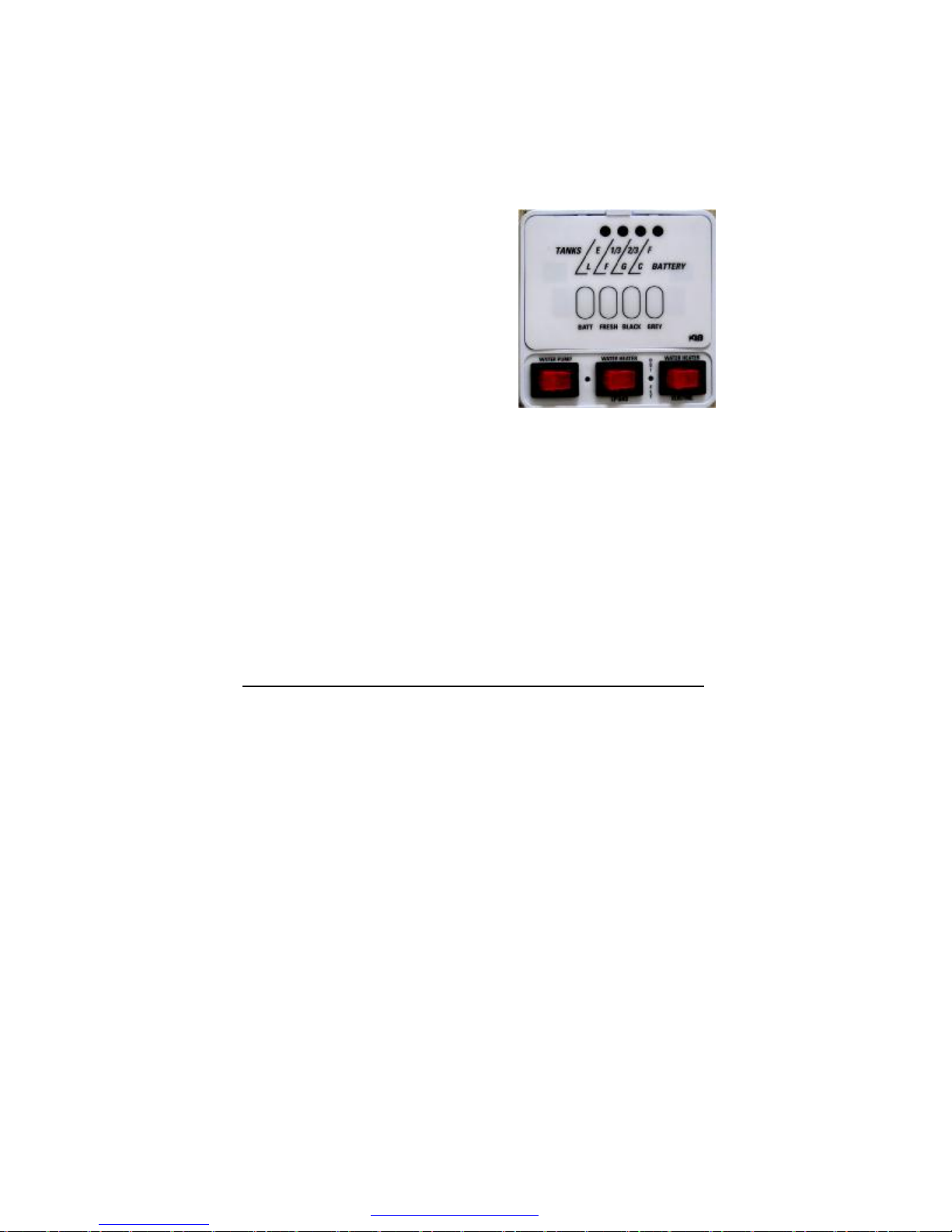
TO TURN OFF WATER HEATER:
1. Turn switch to “OFF” position.
2. Turn off the electric power to the
appliance.
3. Turn off propane supply.
4. If the vehicle is to be stored or the
water heater is going to be turned
off while subject to freezing
temperature, drain the water
heater.
Winterizing Your Water Heater
If your water heater plumbing system is equipped with a bypass kit,
use it to close off the water heater. Drain the water heater
completely and leave the water heater closed off (out of the system)
in the bypass position particularly if you are introducing antifreeze
into the plumbing system.
Antifreeze can be very corrosive to the anode rod creating
premature failure and leave sediment in the tank. If the plumbing
system is not equipped with a bypass kit, and you intend to
winterize by adding antifreeze to the system, remove the anode rod
(storing it for the winter) and replace it with a 3/4 inch drain plug.
REFRIGERATOR_______________________________________
Performance of refrigerators depends on various factors, such as,
energy, venting, leveling, humidity and atmospheric heat
temperatures, but not limited to these. All refrigerators are designed
with absorption type of cooling units requiring careful leveling and
venting conditions.
Leveling: The refrigerator is made to operate within 3 degrees
off level side-to-side and 6 degrees off level front-to-back ( as
looking at the front of the refrigerator ). Operating it at more then
these limits can cause damage to the cooling system and create a
risk of personal injury or property damage. Make sure the vehicle is
level before you operate the refrigerator.
Even being off only 1 degree will be uncomfortable living as 1
degree equals 5 inches higher from one end to the other in a 30
foot travel trailer.
81
PDF created with pdfFactory trial version www.pdffactory.com
Page 89
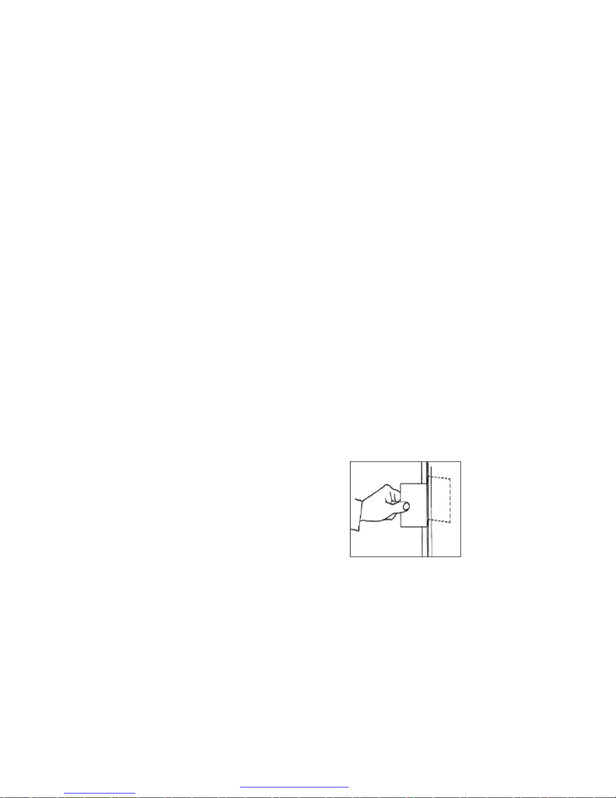
Operation During Travel
While the refrigerator should be level when the vehicle is stopped,
performance during travel is not usually effected.
Venting
For an absorption unit to operate fully it must have two vents. The
lower vent serves as access to service components and allows air to
enter. As the refrigerator heats up, warm air leaves through the
upper vent in the roof or the upper side vent. The roof vent gives
the best “chimney” results. However with correct baffles, side vent
is good. All vents must prevent birds and rodents from entering.
Moisture Reduction Heater
The refrigerator has a heater that prevents moisture from forming on
the center divider between the doors of the freezer and the fresh
food compartment. The heater operates only when the refrigerator is
ON.
Door Sealing
Check the seal of the doors.
If either door does not seal correctly, excess frost will collect inside
the refrigerator. Make sure the doors seal correctly.
* Close each door on a piece of
paper that is about the size and
thickness of a dollar bill.
* Gently pull the paper.
* You should feel a slight drag
between the gasket and the
cabinet.
* Do this on all four sides.
* If you do not feel a slight drag on the
paper, the door does not seal correctly.
* Have your dealer or an authorized Norcold Service
Center correct the seal of the door.
82
PDF created with pdfFactory trial version www.pdffactory.com
Page 90

Door Handles
During travel, the door latch prevents the door from opening. When
closing each door, push the door toward the refrigerator until you
hear a “ clicking sound”.
To open each door, pull the handle away from the refrigerator.
CAUTION
!
Do not use undue force or jerking action when opening the refrigerator door. Air temperature differences can cause a partial vacuum
within the cabinet requiring a firm but steady force to open the
door. A sudden jerk could cause door damage or personal injury.
Refrigerator Storage
Before the refrigerator is stored for an extended (seasonal) period of
time:
- Defrost and clean the interior of the refrigerator.
If the refrigerator is stored for an extended period of time, before
start up:
Make sure there are no obstructions in the vents, the
ventilation air pathway, the burner, the orifice, or the flue area.
For Defrosting and Cleaning the Refrigerator Interior, and other
additional information and operating procedures, see the
manual being supplied by the manufacture.
For full operation details of all of the buttons and it’s function on the
control panel, refer to the Norcold refrigerator owners manual.
OPERATING THE REFRIDGERATOR CONTROLS
Two models are being used during this current year. One model is
fully automatic. You push on/off switch and nothing else. Should you
wish to change temperature, you must move the thermister and wire
inside of the box as per instructions supplied by manufacture.
Second model you choose the energy source and can adjust the
temperature in box by a slide switch on a scale of 1 to 5.
83
PDF created with pdfFactory trial version www.pdffactory.com
Page 91
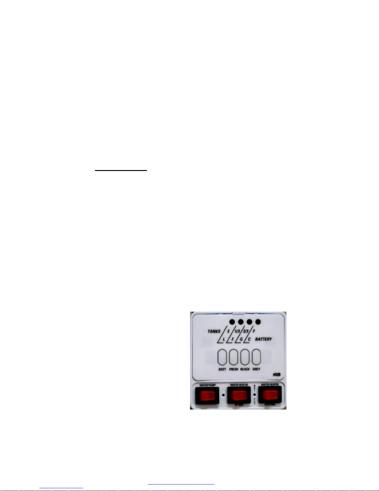
AIR CONDITIONER—ROOF or SIDE
Normal air conditioner is placed on top of roof and all controls are
inside on air box. See instructions supplied by the manufacturer of
product.
A possible future air conditioner may be placed in the sidewall, near
roof line and will installed only by factory personnel.
Both air conditioners operate on 120 VAC power only.
MONITOR PANEL
Your panel through modern technology will supply the charge
condition of your battery, and water level information from your
water tanks.
Operation requires 12-volt DC power, supplied by the battery or
converter. Sensors, one negative and three positive, attached to a
resistor, feed information to the display panel. To operate, place
finger on button and push. A light will illuminate indicating the water
level of tanks or charge condition of battery. “Gallery” will light only
when floor plan includes the second gray water holding tank.
The switch on the lower left corner is for water pump operation.
When in the “ON” position, pump will run until 40 to 45 PSI is
achieved. The pump will shut off and restart at 20 pounds of
pressure. Turn pump switch “OFF” when pump is not in use.
The red switch in the middle at the bottom of monitor panel is for the
Water Heater LP gas. Red switch, lower right hand corner is for
Water Heater electric.
When pushing the battery button,
the highest light coming on
indicates the battery condition: C
-charge at 12.7 volts; G-good at
11.9 volts; F-Fair at 11.2 volts; Llow at 6.0 volts. Press only one
button at a time as one set of
lights serves all functions.
84
PDF created with pdfFactory trial version www.pdffactory.com
Page 92

If problems occur with any appliance while traveling, contact
the appliance manufacture direct. These phone numbers are
listed in the appliance manuals. Manuals should stay in unit at
all times.
Important Phone Numbers
—————————————————————
—————————————————————
—————————————————————
—————————————————————
—————————————————————
—————————————————————
—————————————————————
—————————————————————
—————————————————————
—————————————————————
—————————————————————
—————————————————————
—————————————————————
—————————————————————
—————————————————————
—————————————————————
—————————————————————
—————————————————————
—————————————————————
—————————————————————
————————————————————
85
PDF created with pdfFactory trial version www.pdffactory.com
 Loading...