

Page 1
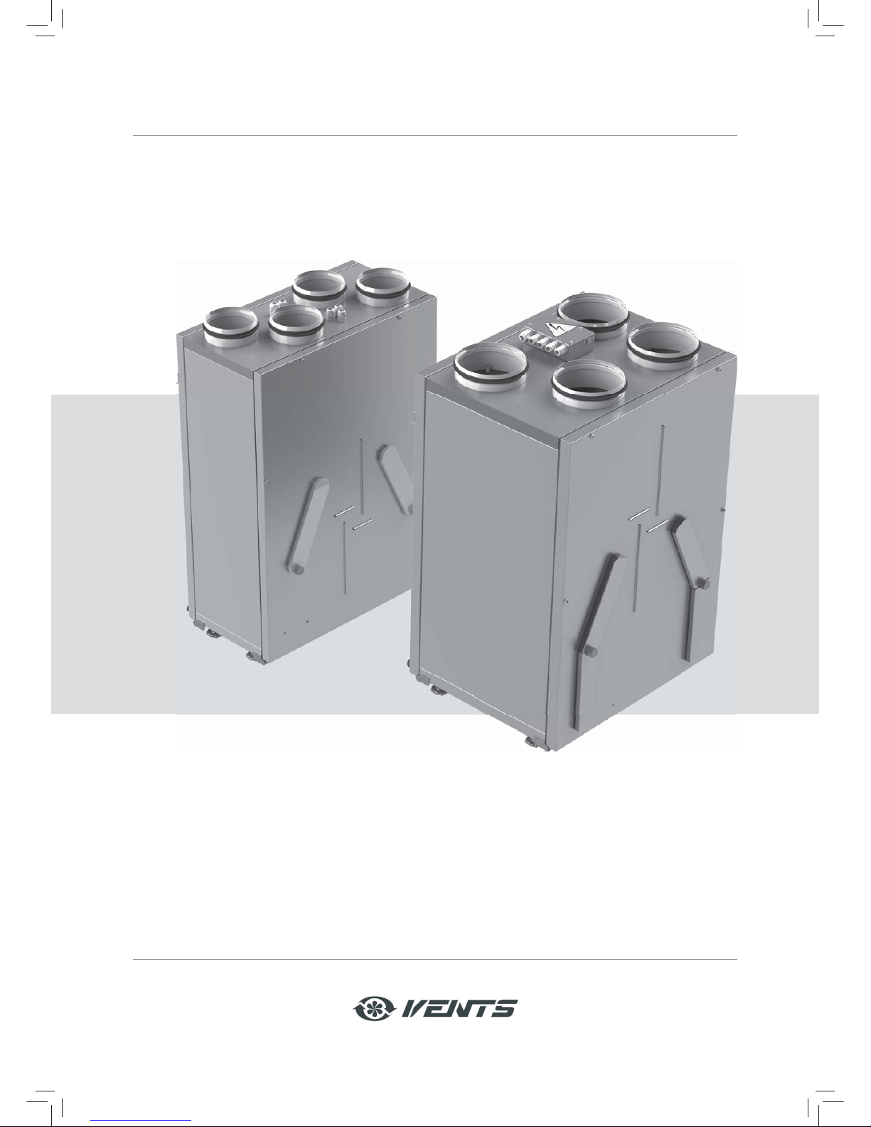
USER'S MANUAL
РУКОВОДСТВО ПОЛЬЗОВАТЕЛЯ
HEAT/HEAT AND ENERGY RECOVERY
VENTILATION UNIT
VUT/VUE 200 V(B) EC
VUT/VUE 250 V(B) EC
Page 2
www.ventilation-system.com2
CONTENTS
Safety requirements . . . . . . . . . . . . . . . . . . . . . . . . . . . . . . . . . . . . . . . . . . . . . . . 2
Purpose . . . . . . . . . . . . . . . . . . . . . . . . . . . . . . . . . . . . . . . . . . . . . . . . . . . . . . . . . . 4
Delivery set . . . . . . . . . . . . . . . . . . . . . . . . . . . . . . . . . . . . . . . . . . . . . . . . . . . . . . . 4
Designation key . . . . . . . . . . . . . . . . . . . . . . . . . . . . . . . . . . . . . . . . . . . . . . . . . . . 4
Technical data . . . . . . . . . . . . . . . . . . . . . . . . . . . . . . . . . . . . . . . . . . . . . . . . . . . . . 5
Unit design and functioning . . . . . . . . . . . . . . . . . . . . . . . . . . . . . . . . . . . . . . . . . 6
Mounting and set-up . . . . . . . . . . . . . . . . . . . . . . . . . . . . . . . . . . . . . . . . . . . . . . . 8
Condensate drain . . . . . . . . . . . . . . . . . . . . . . . . . . . . . . . . . . . . . . . . . . . . . . . . . 11
Connection to power mains . . . . . . . . . . . . . . . . . . . . . . . . . . . . . . . . . . . . . . . . . 12
Unit control . . . . . . . . . . . . . . . . . . . . . . . . . . . . . . . . . . . . . . . . . . . . . . . . . . . . . . . 15
Technical maintenance . . . . . . . . . . . . . . . . . . . . . . . . . . . . . . . . . . . . . . . . . . . . . 16
Troubleshooting . . . . . . . . . . . . . . . . . . . . . . . . . . . . . . . . . . . . . . . . . . . . . . . . . . . 17
Storage and transportation regulations . . . . . . . . . . . . . . . . . . . . . . . . . . . . . . . 18
Manufacturer's warranty . . . . . . . . . . . . . . . . . . . . . . . . . . . . . . . . . . . . . . . . . . . 18
Acceptance certificate . . . . . . . . . . . . . . . . . . . . . . . . . . . . . . . . . . . . . . . . . . . . . . 19
Seller information . . . . . . . . . . . . . . . . . . . . . . . . . . . . . . . . . . . . . . . . . . . . . . . . . 19
Connection certificate . . . . . . . . . . . . . . . . . . . . . . . . . . . . . . . . . . . . . . . . . . . . . . 19
Warranty card . . . . . . . . . . . . . . . . . . . . . . . . . . . . . . . . . . . . . . . . . . . . . . . . . . . . . 19
This user's manual consisting of the technical details, operating instructions and technical specification covers the installation
and mounting of the heat or heat and humidity recovery ventilation unit VUT/VUE 200 V(B) EC (hereinafter "the unit" as mentioned
in the "Safety Requirements" and "Manufacturer's Warranty" sections as well as in warnings and information blocks).
SAFETY REQUIREMENTS
Read the user's manual carefully prior to installing and operating the unit.
Fulfil the user's manual requirements as well as the provisions of all the applicable local and national construction, electrical
and technical norms and standards.
The warnings contained in the user's manual must be considered most seriously since they contain vital personal safety
information.
Failure to follow the rules and safety precautions noted in this user's manual may result in an injury or unit damage.
After a careful reading of the manual, keep it for the entire service life of the unit.
While transferring the unit control the user's manual must be turned over to the receiving operator.
Symbol legend:
WARNING!
DO NOT!
Page 3
www.ventilation-system.com 3
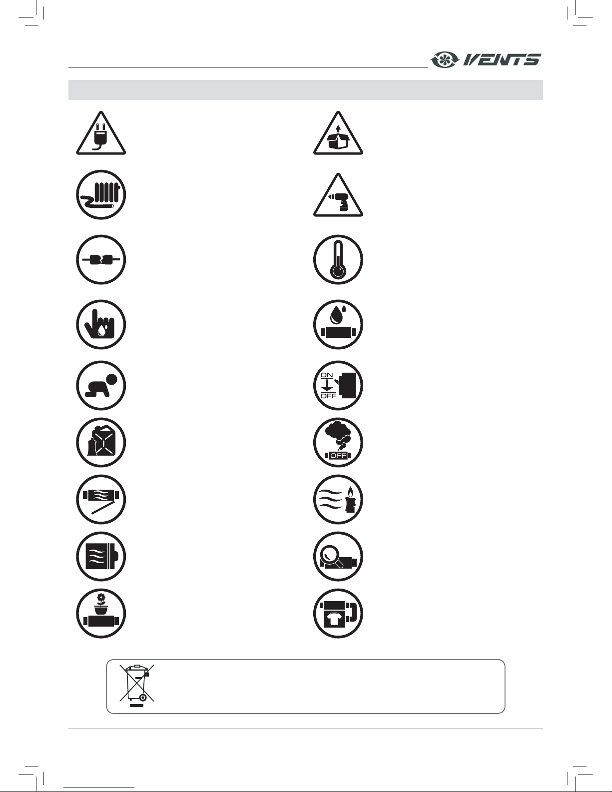
UNIT MOUNTING AND OPERATION SAFETY PRECAUTIONS
• Disconnect the unit from power mains
prior to any installation operations.
• Unpack the unit with care.
• Do not lay the power cable of the unit in
close proximity to heating equipment.
• While installing the unit follow the safety
regulations specific to the use of electric
tools.
• Do not use damaged equipment or cables
when connecting the unit to power mains.
• Do not operate the unit outside the
temperature range stated in the user's
manual.
• Do not operate the unit in aggressive or
explosive environments.
• Do not touch the unit controls with wet
hands.
• Do not carry out the installation and
maintenance operations with wet hands.
• Do not wash the unit with water.
• Protect the electric parts of the unit
against ingress of water.
• Do not allow children to operate the unit.
• Disconnect the unit from power mains prior
to any technical maintenance.
• Do not store any explosive or highly
flammable substances in close proximity to
the unit.
• When the unit generates unusual sounds,
odour or emits smoke disconnect it from
power supply and contact the Seller.
• Do not open the unit during operation.
• Do not direct the air flow produced by the
unit towards open flame or ignition sources.
• Do not block the air duct when the unit is
switched on.
• In case of continuous operation of the unit
periodically check the security of mounting.
• Do not sit on the unit and avoid placing
foreign objects on it.
• Use the unit only for its intended purpose.
THE PRODUCT MUST BE COLLECTED SEPARATELY AT THE END OF SERVICE LIFE.
DO NOT DISPOSE OF AS UNSORTED MUNICIPAL WASTE.
Page 4
www.ventilation-system.com4
PURPOSE
Due to the ability to save heating energy by means of energ y recover y the unit is an impor tant element of energy-eff icient
premises. Being a component unit it may not be commissioned for stand-alone operation.
The unit is designed to ensure continuous mechanical air exchange in houses, offices, hotels, cafes, conference halls and other
utilit y and public spaces as well as to recover the heat energy contained in the air extracted from the premises to warm up the
filtered stream of supply air.
THE UNIT MAY NOT BE OPERATED BY CHILDREN OR PERSONS WITH REDUCED
PHYSICAL, MENTAL OR SENSORY CAPACITIES, OR LACKING THE APPROPRIATE TRAINING.
THE UNIT MUST BE INSTALLED AND CONNECTED ONLY BY PROPERLY QUALIFIED
PERSONNEL AFTER THE APPROPRIATE BRIEFING.
THE CHOICE OF UNIT INSTALLATION LOCATION MUST PREVENT UNAUTHORIZED
ACCESS BY UNATTENDED CHILDREN.
Transported air must not contain any flammable or explosive mixtures, evaporation of chemicals, sticky substances, fibrous
materials, coarse dust, soot and oil particles or environments favourable for the formation of hazardous substances (toxic
substances, dust, pathogenic germs).
DELIVERY SET
Name Quantity
Ventilation unit 1 item
User's manual 1 item
User's manual for control panel 1 item
Control panel 1 item
Drain pipe 1 item
Mounting bracket 1 item
Packing box 1 item
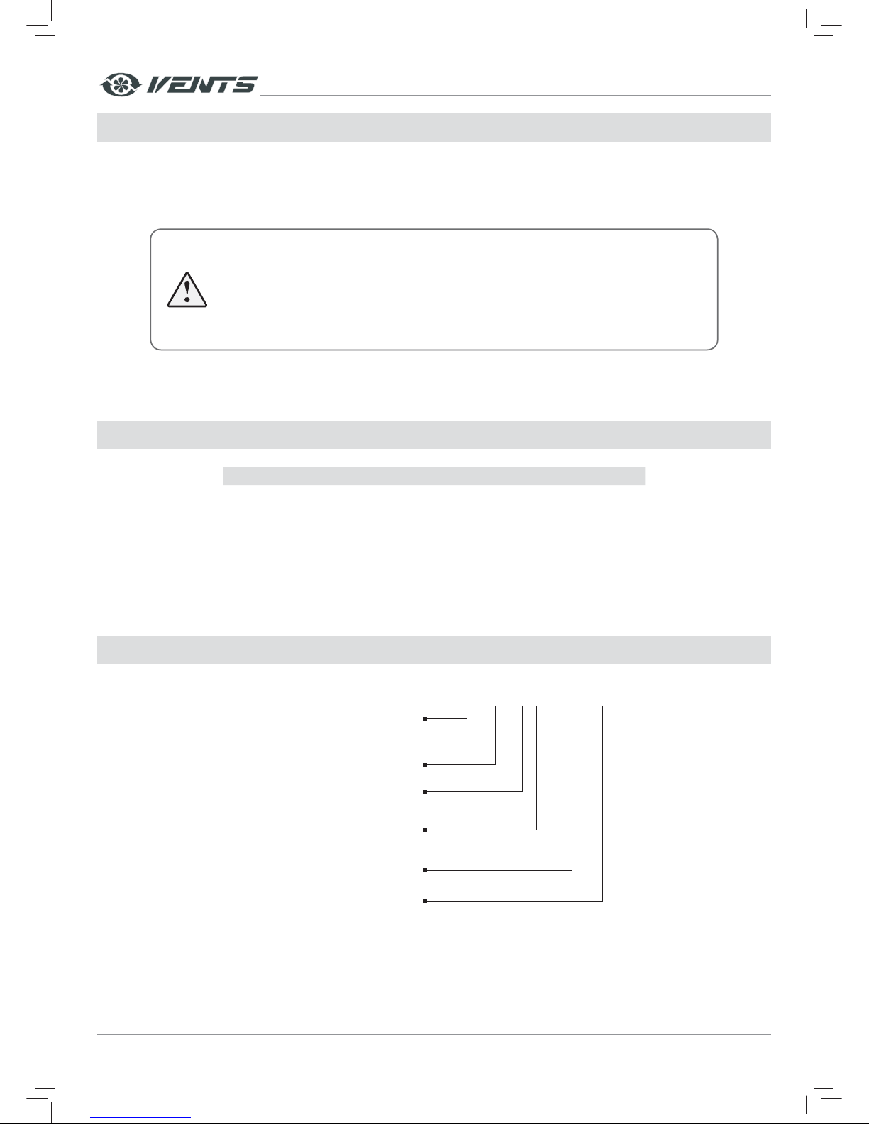
DESIGNATION KEY
X X VX EC X
Motor type
electronically commutated
Control panel
A11
A14
A19
Rated air capacity [m
3
/h]
Ventilation unit type
VUT: ventilation unit with heat recovery
VUE: ventilation unit with heat and energy recovery
Spigot orientation
V: vertical spigot orientation
Extra components
_: no extra components
B: bypass
Page 5
www.ventilation-system.com 5
TECHNICAL DATA
The unit is designed for indoor application at ambient temperature from +1° C up to +40°C and relative humidity up to 80 %.
Hazardous parts access and water ingress protection rating: IP 4 4 for the unit motors and IP 22 for the assembled unit connected
to the air ducts.
The unit design is constantly being improved, so some models may be slightly different from those ones described in this manual.
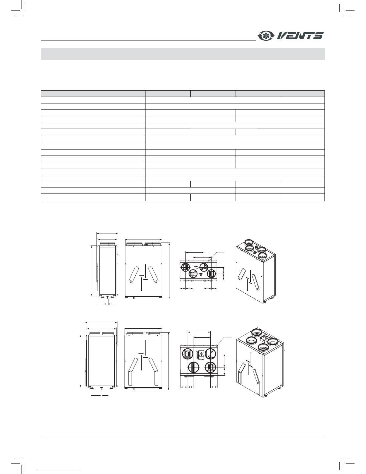
Parameter VUT/VUE 200 V EC VUT/VUE 200 VB EC VUT/VUE 250 V EC VUT/VUE 250 VB EC
Supply Voltage, 50 (60) Hz [V ] 1~ 230
Current consumption [A] 0,81
Max. power consumption [W ] 130 101
Air capacity [m
3
/h] 260 290
RPM [min
-1
] 2050
Noise level, 3 m [dB(A)] 24 25
Transported air temperature [°C]
from -25 up to +60
Casing material
painted steel
Insulation 25 mm, mineral wool 30 mm, mineral wool
Extract filter G3 G4
Supply f ilter G3 (optional F8) G4, F7
Heat exchanger type counter-flow
Heat exchanger material polystyrene/enthalpy membrane
Connected air duct diameter [mm] Ø 125 Ø 125 Ø 160 Ø 160
Heat recovery efficiency [%] 83-98/74-94 85-94/77-90
Weight [kg ]
45 45 51 51
Overall and connection dimensions [mm]
VUT/VUE 200 V(B) EC
Ø 18
564
290
326
771
858
9797
8511585 115
279
279
Ø 124
4 holes
VUT/VUE 250 V(B) EC
Ø 18
567
450
489
788
881
204123
110
110 90
254
344
Ø 160
4 holes
ATT ENTION! Technical data and dimensions of the supplied control panel are indicated in the user's manual for the respective
control panel manual.
Page 6
www.ventilation-system.com6
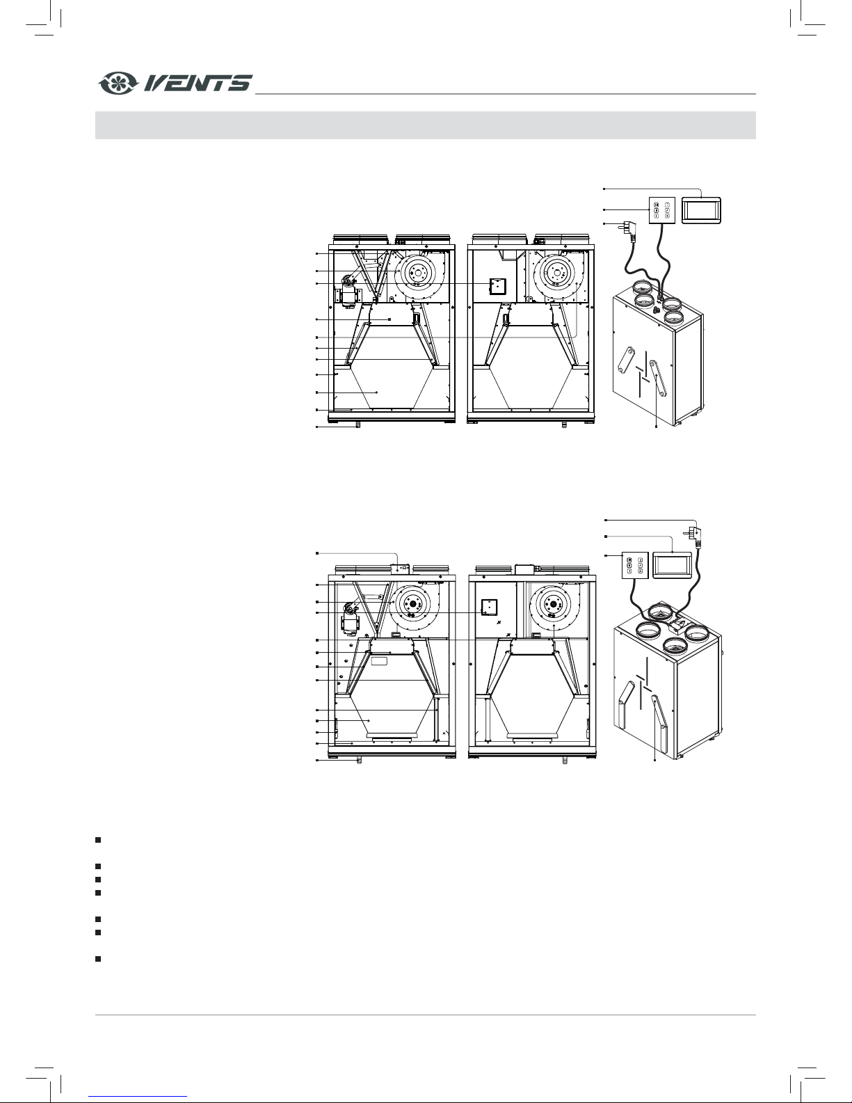
UNIT DESIGN AND FUNCTIONING
VUT/VUE 200 V(B) EC
A14 control panel
Supply fan
HV1 or HV2 humidity sensor
(to be installed upon customer request).
The HV1 humidity sensor is applicable for the control unit A11 or A19.
The HV2 humidity sensor is applicable for the control unit A14).
Bypass damper
(VUT/VUE VB EC)
Supply air lter
Control unit
Counter-ow heat exchanger
Drain pan
Drain pipe
Extract air lter
Freeze protection temperature sensor
Power cable with plug
Removable plates for
lter maintenance
A11 or A19 control panel
Extract fan
VUT/VUE 250 V(B) EC
Supply fan
HV1 or HV2 humidity sensor
(to be installed upon customer request).
The HV1 humidity sensor is applicable for the control unit A11 or A19.
The HV2 humidity sensor is applicable for the control unit A14).
Extract fan
Bypass damper
(VUT/VUE VB EC)
Supply air lter
Internal control unit
Terminal box
Freeze protection temperature sensor
Drain pan
Drain pipe
Extract air lter
Supply air lter
Counter-ow heat exchanger
Removable plates for
lter maintenance
A14 control panel
Power cable with plug
A11 or A19 control panel
The unit casing is made of rigidly fixed panels. The panels are made of painted steel sheet and galvanized steel sheet, filled with heat-
and sound-insulating layer of mineral wool between.
The front panel of the unit has removable plates to enable f ilter replacement.
Location of the service side may be changed.
The temperature difference between the supply and extract air flow temperature leads to condensate generation inside of the unit.
Condensate is collected in the drain pan and is removed outside through the drain pipe.
The energy recover y modification of the unit requires no condensate drain.
Connec tion of the unit to power supply and connection of any control devices to the unit is performed in the control unit and/or in
the terminal box, depending on the specific unit model.
The unit is operated via the control panel and the software. The operation settings are editable through the sof tware. The socket
connector USB on the unit casing enables connection of the unit to a PC or notebook. The sof tware is available for download at our
website: http://vents.ua/images/cat/812_2902_cat_file.rar.
Page 7
www.ventilation-system.com 7
HUMIDITY-CONTROLLED OPERATION OF THE UNIT
If the humidity sensor detects the indoor humidity above the set point, the unit automatically switches to the extract mode.
The humidity sensor for the ventilation unit with the control panel A11 and A19 is integrated in the control panel. Optionally
the humidity sensor may be integrated into the extract air duct. The duct humidity sensor is not included in the delivery set and
is available as a specially ordered accessory. It must be installed independently.
To select the main humidity sensor for the ventilation unit with A11 or A19 control panels, please refer to the user's
m an u al f or t he r es p ec t i ve c on t ro l pa n el , o pe n "E n gi n ee r in g me n u" , se l ec t " Ex t r a o p ti o n s" a nd go t o " H UM I DI T Y S EN SO R SE L EC T I O N" .
Select 1 for the room humidity sensor integrated in the control panel.
Select 2 for the humidity sensor in the air duct.
Activate AUTO mode to enable automatic operation of the unit on feedback from the set humidity sensor. In AUTO mode the
unit switches to the higher speed if the extract air humidity reaches the set humidity point.The unit switches to lower speed after
indoor humidity drops down below the set point. The maximum speed is 100% and the minimum speed is 25% in the AUTO mode.
The ventilation unit with A14 control panel switches to the higher speed up to 100 % if the extract air humidity reaches the
set humidity point. The unit switches to lower speed after indoor humidit y drops down below the set point.
UNIT OPERATION MODES
Some modifications of the unit are equipped with a bypass duct and bypass air damper. The electrically actuated bypass air
damper opens or closes the bypass duct, depending on operation modes. The air flowing through the bypass damper does not
come in contact with the heat exchanger. When the bypass damper is closed, the intake air flows through the heat exchanger.
Heat recovery mode
Warm extract air from the room flows into the unit and is cleaned in the extract filter. Then the air is moved through the heat
exchanger and is exhausted outside with the extract fan.
Cold fresh air from outside flows into the unit, where it is cleaned in the supply filter. Then the air f lows through the heat
exchanger and is moved to the room with the supply fan.
Supply air is heated in the heat exchanger by transferring the heat energy of warm and humid extract air to the cold fresh air.
The air flows are fully separated while flowing through the heat exchanger. Heat recovery minimizes heat losses, which reduces
the cost of space heating in the cold season.
Freeze protection mode
Defrosting mode is actuated on feedback from the freeze protection temperature sensor to enable the heat exchanger freeze
protection in the cold season. The freeze protection temperature sensor is located in the exhaust air duct. The freeze protection
operation mode is activated when the exhaust air temperature falls down to +3 °C. The unit rever ts to the previous operation
mode after the temperature increase.
To activate the freeze protection mode for the ventilation unit with A11 or A19 control panel, please refer to the user's
manual for the respective control panel, open "Engineering menu", select "Extra options". To activate the freeze protection mode
select the required option, suitable for the ventilation unit model and edit its current status:
• For the ventilation units with a bypass damper select "BYPASS OPERATION MODES" and select "ON".
• For the ventilation units without a heater select "SUPPLY FAN OFF" and select "ON".
• For the ventilation units with integrated heater(s) select "HE ATING CONTROL" and selec t "ON".
For the ventilation units with A14 control panel the freeze protection mode is activated automatically by turning off the
supply fan, hence no activation is required.
Summer cooling mode
The extract air flows through the bypass duct and does not come in contact with the heat exchanger. The bypass duct is
opened with a bypass damper. The temperature of the air is not changed after passing through the heat exchanger.
Page 8
www.ventilation-system.com8
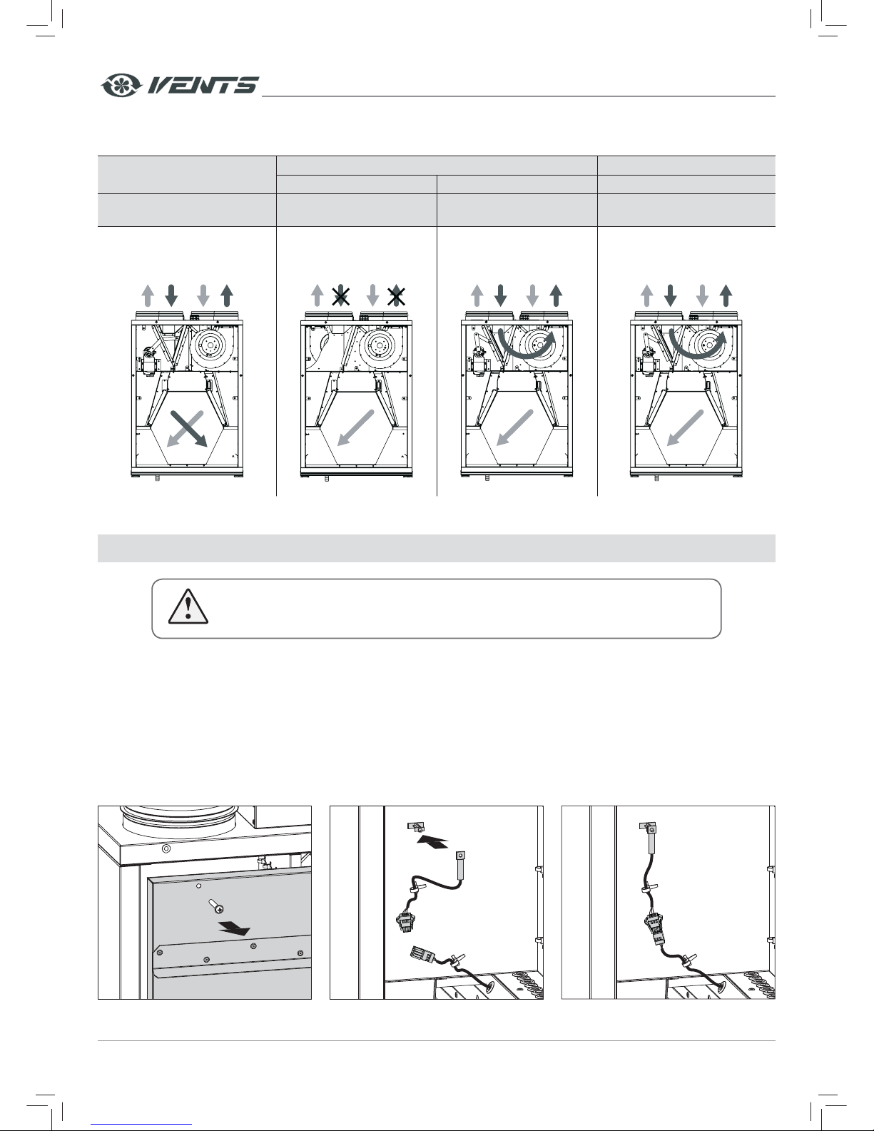
AIR FLOW DIRECTION
The air flow direction for various operation modes of the VUT/VUE 200 V(B) EC unit is shown below
Heat recovery mode
Freeze protection mode Summer cooling mode
Supply fan is off Bypass duct is closed Bypass duct is closed
VUT/VUE 200 V(B) EC
VUT/VUE 250 V(B) EC
VUT/VUE 200 V EC
VUT/VUE 250 V EC
VUT/VUE 200 V(B) EC
VUT/VUE 250 V(B) EC
VUT/VUE 200 V(B) EC
VUT/VUE 250 V(B) EC
INTAKE AIR
SUPPLY AIR
EXTRACT AIR
EXHAUST AIR
INTAKE AIR
SUPPLY AIR
EXTRACT AIR
EXHAUST AIR
INTAKE AIR
SUPPLY AIR
EXTRACT AIR
EXHAUST AIR
INTAKE AIR
SUPPLY AIR
EXTRACT AIR
EXHAUST AIR
MOUNTING AND SET-UP
THE UNIT MUST BE MOUNTED BY A QUALIFIED EXPERT ONLY, PROPERLY TRAINED AND
HAVING THE REQUIRED TOOLS AND MATERIALS.
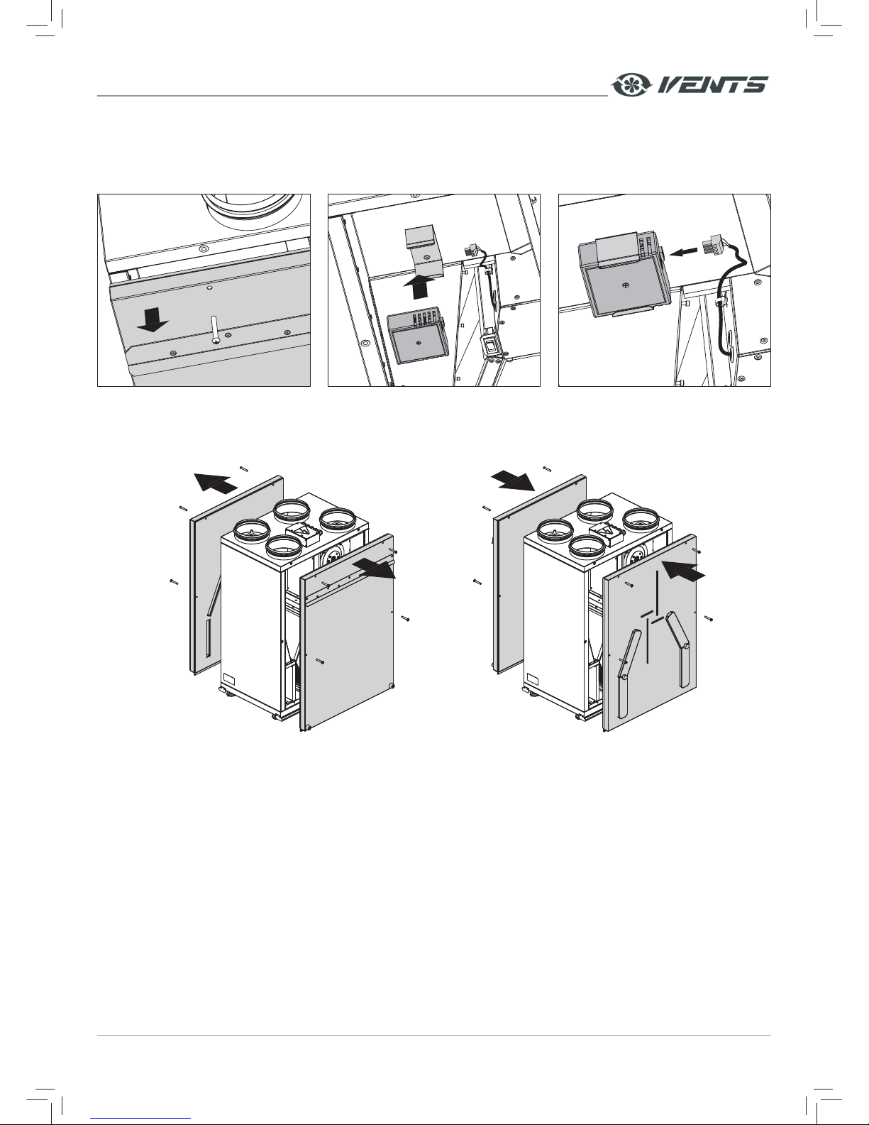
HUMIDITY SENSOR MOUNTING IN THE EXTRACT AIR DUCT
ATTENTION!
The humidity sensor must be installed prior to unit mounting.
Mounting steps for the HV1 humidity sensor (for the ventilation units with A11 or A19 control panel):
• Remove the screws that retain the panel on side of the extract spigot and remove it.
• Insert the humidity sensor on the mount.
• Connect the humidity sensor contact socket to the contact socket with a cable from the control unit. The contact socket is pre-
wired.
Page 9
www.ventilation-system.com 9
Mounting steps for the HV2 humidity sensor (for the ventilation units with A14 control panel):
• Remove the screws that retain the panel on side of the extract spigot and remove it.
• Insert the humidity sensor on the mount.
• Connect the humidity sensor contact socket to the contact socket with a cable from the control unit. The contact socket is pre-
wired.
Вытяжной
патрубок
SERVICE SIDE CHANGE
• Unscrew the front panel on the service side and the back panel.
• Remove the panels and change their positions. Fix the panels with screws.
Note: the service panel change is shown for VUT/VUE 250 V(B) EC.
Page 10
www.ventilation-system.com10
UNIT MOUNTING
To attain the best performance of the unit and to minimise turbulence-induced air pressure losses while mounting connect a straight
air duct section on both sides of the unit.
Minimum straight air duct length:
• equal to 1 air duct diameter on intake side.
• equal to 3 air duct diameters on outlet side.
If the air ducts are not connected or the connected air ducts are too short, protect the unit parts from ingress of foreign objects by
covering the spigots with a protecting grille or other protecting device with mesh width not more than 12.5 mm to prevent uncontrollable
access to the fans.
While installing the unit ensure convenient access for subsequent maintenance and repair. The unit must be mounted on an even
wall. Mounting the unit to an uneven surface can lead to the unit casing distortion and operation disturbance.
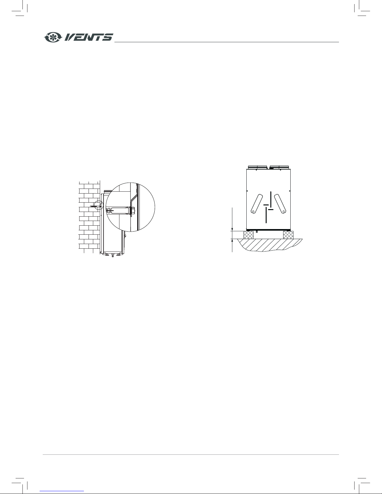
Unit wall mounting
Fasteners for wall-mounting are not included into delivery set
and need to be ordered separately. While selecting appropriate
fasteners consider the material of the mounting surface as well
as the weigh of the unit, refer technical data. For selection of the
fasteners for unit mounting please refer to service technicians.
Fix the wall mounting bracket at a required height and fix the unit
on the hook.
Unit floor mounting
Install the unit on the pre-set floor supports, minimum 150 mm
height, to ensure sufficient access for the drain pipe connection
to the U-trap and for condensate drain system mounting.
min 150 mm
Note: the mounting is shown for VUT/VUE 250 V(B) EC.
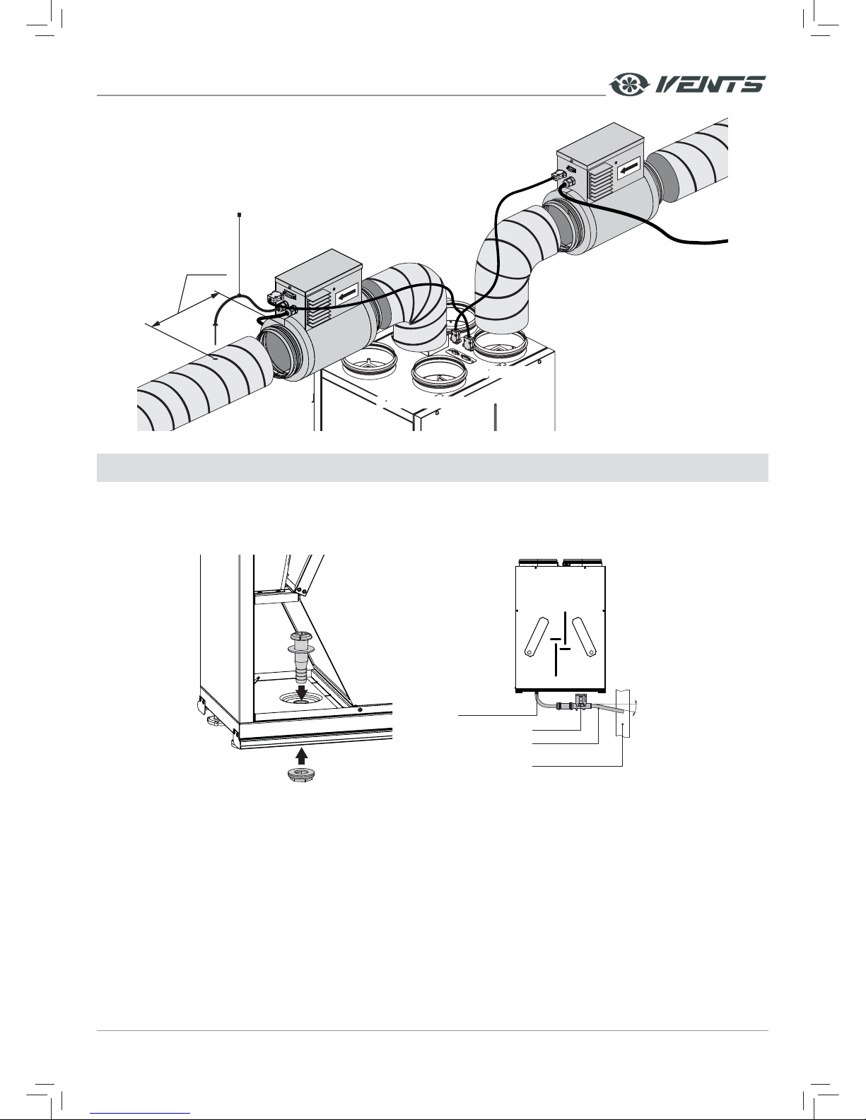
MOUNTING AND WIRING OF THE HEATERS TO THE UNIT WITH A19 CONTROL PANEL
NKP and NKD electric heaters are not included in the deliver y set of the air handling unit and are available as specially ordered
accessory.
The heaters are rated for connection to 230V / 50 (60) Hz power supply.
NKP and NKD heaters may be connected to the unit both as a single unit each or jointly.
Prior to connecting the heater to the air handling unit remove the pre-installed plugs from the internal socket connectors.
WARNING!
• Do not remove the plugs before the heaters are connected to the air handling unit.
• Make sure to cover the socket connec tor with the plugs after dismantling of the connecting cable.
• If only one heater is connected, do not remove the plugs from the other socket connector that is not in use.
• If the socket connectors are not covered with plugs for any reasons, the ventilation unit does not start during connection to
power supply and the control panel displays DI1 and DI3 errors for NKP and DI1, DI3 and TE5 errors for NKD. Turn the unit
off and cover the socket connectors with the plugs to troubleshoot the errors.
Attach the NKP heater to the air duct connected to the intake air spigot.
The electric heater is connec ted to the unit via a connecting cable with DB-9F socket connectors connected to the external socket
connectors DB-9F on the unit and the heater.
Attach the NKD heater to the air duct connected to the supply air spigot. Install the air temperature sensor TE5 in the supply air
duct. Keep the minimum distance between the heater and the sensor 1 m.
Connect the electric heater to the unit via a connecting cable with DB-15M socket connectors inserted to the DB-15F external
socket connectors on the unit and the heater.
Page 11
www.ventilation-system.com 11
NKD
NKP
С УЛИЦЫINTAKE AIR
В ПОМЕЩЕНИЕ
SUPPLY AIR
Temperature sensor
ТЕ5
min 1 m
CONDENSATE DRAINAGE
The VUT V(B)EC unit requires condensate drainage.
The hole for the drain pipe is located at the bottom of the unit. Remove the plug from the hole, open the service panel and install the
drain pipe from the delivery set into the hole, then connect the drain pipe to the sewage system using the SG-32 U-trap kit (available
upon separate order). While laying the hoses provide the slope downwards min 3˚.
min 3°
DRAIN
HOSE
U-TRAP
SEWAGE
SYSTEM
DRAIN
PIPE
Note: installation of the drain pipe is shown for VUT 200 V(B) EC.
Page 12
www.ventilation-system.com12
POWER MAINS CONNECTION
DISCONNECT THE UNIT FROM POWER SUPPLY PRIOR TO ANY ELECTRIC INSTALLATION
OPERATIONS. INSTALLATION SHALL ONLY BE PERFORMED BY A PROFESSIONAL ELECTRICIAN.
THE RATED ELECTRICAL PARAMETERS ARE STATED ON THE RATING PLATE.
ANY TAMPERING WITH THE INTERNAL CONNECTIONS IS PROHIBITED AND WILL VOID THE
WARRANTY.
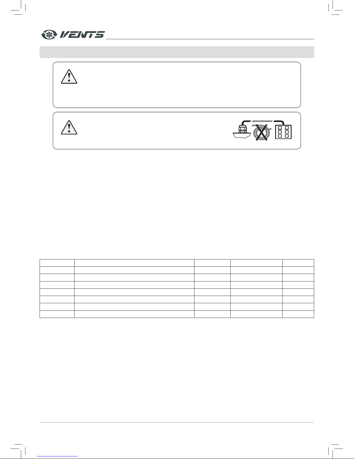
DO NOT LAY THE CABLE IN CLOSE PROXIMITY TO THE CONTROL
PANEL CABLE! DO NOT COIL THE CABLE FROM THE CONTROL
PANEL IN LOOPS WHILE LAYING IT.
• The unit is rated for connection to single-phase ac 230 V/ 50(60) Hz power mains.
• The house cabling must have an integrated automatic circuit breaker (not included in the delivery set). The external circuit
breaker position must ensure unhampered access for emergency shutdown of the unit. The recommended trip current of the
circuit breaker is 2 A.
• Connect the unit to power mains using the pre-wired power cable with a Euro Plug.
ATT ENTION!
Connect the heater(s) to power supply prior to connecting the unit to power supply.
Connection of the heater(s) to power supply (for the units with A19 control panel only)
The control unit A19 enables connection of the heater(s). If the unit is connected to power supply before connection of the
heater(s) the control panel displays the following errors: DI1 and DI3 for NKP and DI1, DI3 and TE5 for NKD. To troubleshoot the errors
turn the unit off and restart it with the activated heater(s).
Connection of extra external devices
The unit has an option of additional external controls connection. Additional connected devices are not included in the delivery
set and are available as specially ordered accessories. Extra connections to the unit are shown in dotted lines in the External wiring
diagram. For connection of external controls use insulated durable heat-resistant cables and wires. The required cable parameters
are indicated in the table.
Designations Description Cable type Maximum cable length Note
CCU* Freon cooler 2x0.75 m
2
20 m no
SM1* Supply air damper actuator 2x0,75 m
2
20 m LF 230
SM2* Extract air damper actuator 2x0,75 m
2
20 m LF 230
PK* Contact for fire alarm panel 2x0,75 m
2
20 m no
KH* Contact for kitchen hood 2x0,5 m
2
20 m no
P1 Control panel 4x0,25 m
2
10 m
TE1 External temperature sensor (inside the unit)
* Not included in th e delivery set
Page 13
www.ventilation-system.com 13
• Connection of the automatic fire extinguishing system contact PK (nc, c)
While connecting the contact of the fire extinguishing system for the unit with A14 control panel remove the
jumper between the RK terminals. The connection relies on a normally closed dr y contact. In case of a signal from a the
central fire-fighting board the contact opens the control circuit and cuts off power supply to the unit.
The connection (no, c) of the unit with A11 and A19 control panel relies on a normally open dry contact. In case of
a signal from a the central fire-fighting board the contact closes the control circuit and cuts off power supply to the unit.
• Connection of the external control device such as CO2 sensor (no, c).
Connect the CO2 sensor to the terminals NO and C. The connection relies on a normally open dry contact. As the contact is
closed, the unit turns to the maximum speed.
• Connection of the humidity sensor HV1 or HV2 (+U, 0-10V, Gnd).
Connect the socket of the humidity sensor and the socket of the cable (pre-wired) from the control unit. The sensor is not
included in the deliver y set and is available as a specially ordered accessory.
• Connection of the external supply air damper SM1 (L, N) and exhaust air damper SM2 (L, N).
The air dampers and the electric actuator are not included in the delivery set and are available as specially ordered
accessories. For connection of the air dampers use an electric ac tuator of LF 230 BELIMO type rated for 230 V power voltage
and on/off control logic.
• Connection of the kitchen hood KH (no, c)
The unit with A19 control panel enables connection of the kitchen hood. As the kitchen hood is activated, the dry contact
is closed and the unit turns to the maximum speed.
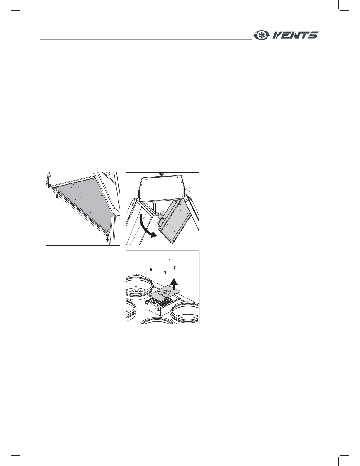
Access to the control unit
• Unscrew the front panel on the service side
and remove it.
• Remove the hear exchanger.
• Remove the screws that retain the electric
connection plate and push it downwards.
For VUT/VUE 200 V(B) EC models both terminal
block s X1 and S2 are located on the ele ctric connec tion
plate of the internal control unit.
For VUT/VUE 250 V(B) EC models the terminal block
X1 is located on the electric connection plate. .
Access to the terminal box
(only for VUT/VUE 250 V(B) EC)
• The terminal block X2 is located in the external
terminal box on the unit casing.
• To access the terminal block X2 remove the
screws on the terminal box and remove the lid.
Page 14
www.ventilation-system.com14
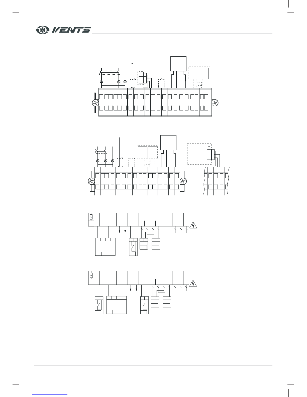
EXTERNAL WIRING DIAGRAM
VUT/VUE 200 V(B) EC A14
234 1098765432111
L
1
External device
NO
contact
(CO
2
sensor)
PK
re alarm panel
(remove the jumper while connecting the contact)
230 V/ 50-60 Hz
Control
panel
P1
-
Tx Rx +
Gnd Tx Rx +U
3
21Gnd
+U
0-10V
Gnd+U 0-10V noNPEncc c
X1 X2
12
SM-L13SM-N
Humidity
sensor HV2
White
Brown
Green
Yellow
XP
QF
Electric actuators of
the external air dampers
SM1
приток
L1 N
SM2
вытяжка
L1 N
VUT/VUE 250 V(B) EC A14
Control
panel
P1
-
Tx Rx +
White
Brown
Green
Yellow
Electric actuators of
the external air dampers
SM1
L1 N
SM2
L1 N
1
L
3PE4nc5c6no7
c
10
Gnd11Tx12Rx13+U
2
N
8
SM-L9SM-N
X1
PK
re alarm panel
(remove the jumper while connecting the contact)
External device
NO
contact
(CO
2
sensor)
230 V/ 50-60 Hz
XP
QF
3
21GND
+U
0-10V
Humidity
sensor
HV2
5+U6
0-10V7GND
X2
VUT/VUE 200 V(B) EC A11
14
A
13
B
12
Gnd
11
+12V
10no9
c8no
76 5
c
3PE2N1
L
SM1
LN
SM2
L
21 21
N
CCU
(no-contact)
BA
+12V
Gnd
P1
no c
PK
Power input
230 VAC
Х1
LLNN4LL
— ELECTRIC SHOCK HAZARD
VUT/VUE 250 V(B) EC A19
131415
Acno
12
B
11
Gnd
10
+12V
9no8
c7no
65 4
c
3PE2N1
L
SM1
LN
SM2
L
21 21
N
CCU
(no-contact)
BA
+12V
Gnd
P1
no c
PK
Power input
230 VAC
Х1
LLNN
— ELECTRIC SHOCK HAZARD
no c
KH
Page 15
www.ventilation-system.com 15
UNIT CONTROL
The unit is operated via the control panel A11, A14 or A19 depending on the unit model. For details, please refer to the user's manual
for the respective control panel.
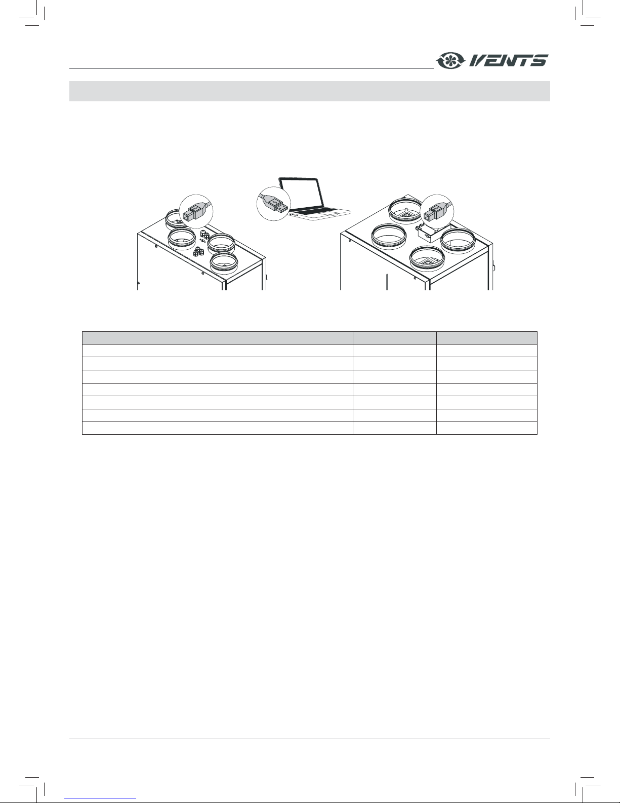
UNIT CONTROL WITH SOFTWARE
To enable operation of the unit using the pre-installed software connection the unit to a laptop or PC via a USB cable with a Type A
and Type B connectors. The USB cable is not included in the scope of delivery.
USB Type B
USB Type A
USB Type B
VUT/VUE 200 V(B) A14 VUT/VUE 250 V(B) A14
The software enables editing the unit parameters:
Parameter Factory setting Control range
Zero speed (off) [%] 0 0 - 100
Low speed [%] 40 0 - 100
Medium speed [%] 70 0 - 100
High speed [%] 100 0 - 100
Unit speed with the closed dry contact of the external control unit [%] 100 0 - 100
Filter cleaning (replacement) interval 2160 (3 months) 0 - 10000
Humidity level [%] 60 30 - 80
The list of the adjustable parameters can be expanded in new versions of the software.
Setting, troubleshooting and upgrading of the software version is made by the service technician.
The software is available for downloading on our website: http://vents.ua/images/cat/812_2902_cat_file.rar.
Page 16
www.ventilation-system.com16
TECHNICAL MAINTENANCE
DISCONNECT THE UNIT FROM POWER MAINS PRIOR TO ANY MAINTENANCE
OPERATIONS.
The unit must undergo technical maintenance 3 to 4 times a year. Maintenance includes general cleaning of the unit and the
following operations:
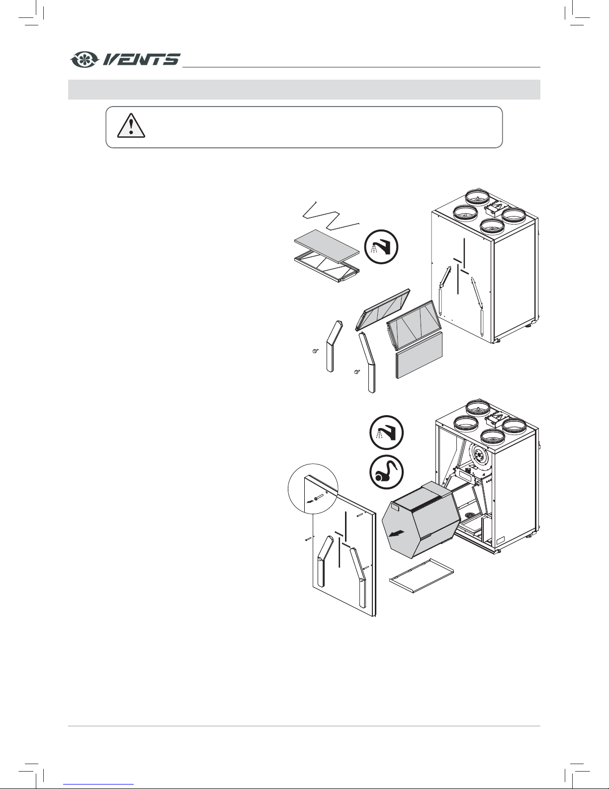
1. Filter maintenance (3-4 times per year).
Clogged filters increase air resistance in the system and
reduce supply air volume. The filters require cleaning not
less than 3-4 times per year.
Cleaning of F7 and F8 filters
Remove the clogged f ilters from the unit. Clean the
filters with a vacuum cleaner and install these. After
two cleanings filters must be replaced. For new f ilters
contact the Seller.
Cleaning of G4 filters
Remove the clogged f ilters from the unit. Then
remove the retaining clamps to pull the filters from the
frames. Rinse the filters with water and let these dry out.
After that reassemble the filters in the reverse orders
and install to the unit. Note: access to the filters is shown
for VUT/VUE 250 V(B) EC.
2. Heat exchanger maintenance (once per year).
Some dust may accumulate on the heat exchanger
block even in case of regular maintenance of the filters. To
maintain the high heat exchange efficiency, regular cleaning
is required.
Wet cleaning of the heat exchanger
Remove the contaminated heat exchanger from the
unit. Rinse it with warm mild detergent solution. Let the
heat exchanger dry out and install it to the unit.
Dry cleaning of the heat exchanger
Remove the contaminated heat exchanger from the
unit. Clean with a vacuum cleaner using a narrow nozzle.
Install the heat exchanger to the unit. Note: access to the
heat exchanger is shown for VUT/VUE 250 V(B) EC.
G4
F8
Page 17
www.ventilation-system.com 17
3. Fan maintenance (once per year).
Even in case of regular maintenance of the filters, some dust may accumulate inside the fans and reduce the unit performance and
decrease supply air flow.
Clean the fans with a soft brush or cloth. No water and abrasive detergent, sharp objects or solvents are allowed for cleaning to prevent
the impeller damage.
4. Condensate drainage maintenance (once per year).
The drain pipes may get clogged with the extracted particles.
Pour some water inside the drain pan to check the pipe for clogging. Clean the U-trap and the drain pipe if required.
5. Ductwork system maintenance (once in 5 years).
Regular maintenance operations listed above may not completely prevent dust accumulation in the unit, which results in reducing
performance of the unit. Duct maintenance means regular cleaning or replacement.
6. Control unit maintenance (if necessary).
The control unit maintenance must be performed by an expert qualified for unassisted operations with electrical installations with the
voltage up to 1000 V after careful reading of the user's manual.
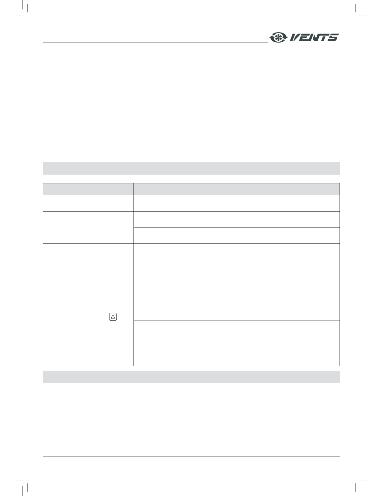
TROUBLESHOOTING
Trouble Possible reasons Troubleshooting
The fan does not get started. No connection to power supply.
Make sure the power supply line is connected
correctly, otherwise troubleshoot a connection error.
Low air flow.
Filters, fans or the heat exchanger
are soiled.
Clean or replace the filters. Clean the fan(s) and
the heat exchanger.
The ventilation system is
contaminated or damaged.
Clean the ventilation system components. Replace
the damaged components.
Noise, vibration.
The impeller is soiled. Clean the impellers.
The screw connection of the fan or
the casing is loose.
Tighten the mounting screws of the fans or
the casing against stop.
Water leakage.
The drainage system is clogged
or damaged. Wrong installation of
the drain system.
Clean the drainage system. Check the drain line
slope angle. Make sure that the U-trap is filled with
water and the drain pipes are frost protected.
Displayed alarm indicator
on
the control panel.
Communication loss (cable or wire
breakdown) between the control
panel and the ventilation unit.
Check the power and connection cables and wires
between the control panel and the air handling
unit for integrity using a multimeter. If unassisted
troubleshooting fails, please contact the product Seller.
Wrong cable installation.
Make sure the cable installation is completed
according to the requirements. Otherwise install
the cable as required.
Displayed DI1 and DI3 errors on
the control panel. The error coding is
the same for both heaters.
Activated heating mode in
the control panel whereas
the heater is missing.
For error troubleshooting deactivate the heating
mode. If the errors are displayed after that please
contact the product Seller.
STORAGE AND TRANSPORTATION REGULATIONS
Store the unit in the manufacturer's original packing box in a dry ventilated premise at ambient temperatures from +5 °C up to + 40 °C.
Storage environment must not contain aggressive vapours and chemical mixtures provoking corrosion, insulation and sealing
deformation.
Use suitable hoist machinery for handling and storage operations to prevent possible damage to the unit. Follow the handling
requirements applicable for the particular type of cargo.
The unit can be carried in the original packing by any mode of transport provided proper protection against precipitation and
mechanical damage.
Avoid sharp blows, scratches or rough handling during loading and unloading.
Do not expose the unit to sudden changes in temperature. Such changes can lead to condensation of moisture inside the unit and
performance disturbance during the unit activation.
Prior to the initial power-up after transportation at sub-zero temperatures allow the unit to warm up at room temperature for at
least 2 hours.
Page 18
www.ventilation-system.com18
MANUFACTURER’S WARRANTY
The manufacturer hereby warrants normal operation of the unit for 24 months after the retail sale date provided the user's
observance of the transportation, storage, mounting and operation regulations.
Should any malfunctions occur in the course of the unit operation through the Manufacturer's fault during the guaranteed period
of operation the user is entitled to elimination of faults by the manufacturer by means of warranty repair at the factory free of charge.
The warranty repair shall include work specific to elimination of faults in the unit operation to ensure its intended use by the user
within the guaranteed period of operation. The faults are eliminated by means of replacement or repair of the unit components or a
specific part of such unit component.
The warranty repair does not include:
• Routine technical maintenance;
• Unit installation / dismantling;
• Unit setup.
To benefit from warranty repair the user must provide the unit, the user's manual with the purchase date stamp and the payment
document certifying the purchase.
The unit model must comply with the one stated in the user's manual.
Contact the Seller for warranty service.
The manufacturer's warranty does not apply to the following cases:
• User's failure to submit the unit with the entire delivery package as stated in the user's manual including submission with missing
component parts previously dismounted by the user.
• Mismatch of the unit model and the brand name with the information stated on the unit packing and in the user's manual.
• User's failure to ensure timely technical maintenance of the unit.
• External damage to the unit casing (excluding external modifications as required for installation) and internal components caused
by the user.
• Redesign or engineering changes to the unit.
• Replacement and use of any assemblies, parts and components not approved by the manufacturer.
• Unit misuse.
• User's violation of the unit installation regulations.
• User's violation of the unit control regulations.
• Unit connection to the power mains with a voltage different from the one stated in the user's manual.
• Unit breakdown due to voltage surges in the power mains.
• Discretionary repair of the unit by the user.
• Unit repair by any persons without the manufacturer's authorization.
• Expiration of the unit warranty period.
• User's violation of the unit transportation regulations.
• User's violation of the unit storage regulations.
• Wrongful actions against the unit committed by third parties.
• Unit breakdown due to circumstances of insuperable force (fire, flood, earthquake, war, hostilities of any kind, blockades).
• Missing seals if provided by the user's manual.
• Failure to submit the user's manual with the unit purchase date stamp.
• Missing payment document certifying the unit purchase.
FOLLOWING THE REGULATIONS STIPULATED HEREIN WILL ENSURE A LONG AND
TROUBLE-FREE OPERATION OF THE UNIT.
USERS' WARRANTY CLAIMS SHALL BE SUBJECT TO REVIEW ONLY UPON PRESENTATION
OF THE UNIT, THE PAYMENT DOCUMENT AND THE USER'S MANUAL WITH THE PURCHASE
DATE STAMP.
Page 19
www.ventilation-system.com 19
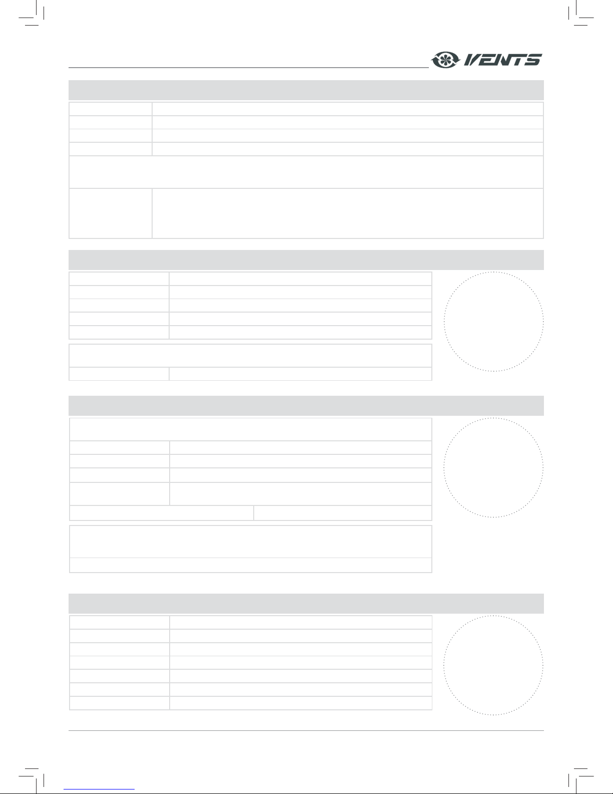
ACCEPTANCE CERTIFICATE
Unit Type Is compliant with the technical specifications and is recognized as serviceable.
Model VUT / VUE ______ V __ EC ____
Serial Number
Manufacture Date
The produc t is in compliance with EU norms and standards on low voltage guidelines and electromagnetic compatibility.
We hereby declare that the product complies with the provisions of Electromagnetic Council Direc tive 2014/30/EU,
Low Voltage Directive 2014/35/EU and CE-marking Directive 93/68/EEC.
Quality
Inspector's Stamp
SELLER INFORMATION
Seller
Address
Phone Number
E-mail
Purchase Date
This is to certify acceptance of the complete unit delivery with the user's manual. The warranty
terms are acknowledged and accepted.
Customer's Signature
Seller's Stamp
INSTALLATION CERTIFICATE
Installation Company Stamp
The unit has been connec ted to power mains pursuant to the requirements stated in the present
user's manual.
Company Name
Address
Phone Number
Installation
Technician's Full Name
Installation Date: Signature:
The unit has been installed in accordance with the provisions of all the applicable local and national
construction, electrical and technical codes and standards. The unit operates normally as intended
by the manufacturer.
Signature:
WARRANTY CARD
Seller's Stamp
Unit Type HEAT/HEAT AND ENERGY RECOVERY VENTILATION UNIT
Model VUT / VUE ______ V __ EC ____
Serial Number
Manufacture Date
Purchase Date
Warranty Period
Seller
Page 20

V106-5EN-01
 Loading...