

Page 1
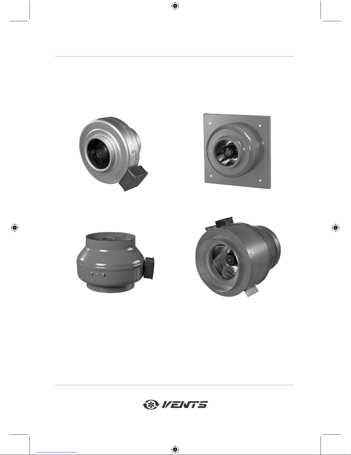
USER'S MANUAL
VKM/VKMz/VC
Centrifugal inline fans
V05EN-07.indd 1 28.04.2016 16:22:21
Page 2
www.ventilation-system.com
2
CONTENTS
Safety requirements .................................................................................................................... 2
Purpose ............................................................................................................................................ 4
Delivery set ..................................................................................................................................... 4
Designation key ............................................................................................................................ 5
Technical data ............................................................................................................................... 6
Unit design and operating principle ...................................................................................... 11
Mounting ........................................................................................................................................ 13
Connection to power mains ...................................................................................................... 14
Control ............................................................................................................................................. 15
Technical maintenance .............................................................................................................. 16
Storage and transportation regulations ............................................................................. 16
Manufacturer's warranty ........................................................................................................... 17
Acceptance certificate ............................................................................................................... 18
Seller information ........................................................................................................................ 18
Installation certificate ................................................................................................................ 19
Warranty card ............................................................................................................................... 19
This user's manual consisting of the technical details, operating instructions and technical specication
covers the installation and mounting of the VKM/VKMz/VC centrifugal fan (hereinafter referred to as "the fan"
or "the unit" as mentioned in the "Safety requirements" and "Manufacturer's warranty" sections as well as in
warnings and information blocks).
SAFETY REQUIREMENTS
Read the user's manual carefully prior to installing and operating the unit.
Full the user's manual requirements as well as the provisions of all the applicable local and national
construction, electrical and technical norms and standards.
The warnings contained in the user's manual must be considered most seriously since they contain vital
personal safety information.
Failure to follow the rules and safety precautions noted in this user's manual may result in an injury or unit
damage.
After a careful reading of the manual, keep it for the entire service life of the unit.
While transferring the unit control the user's manual must be turned over to the receiving operator.
Symbol legend:
WARNING!
DO NOT!
V05EN-07.indd 2 28.04.2016 16:22:22
Page 3
3
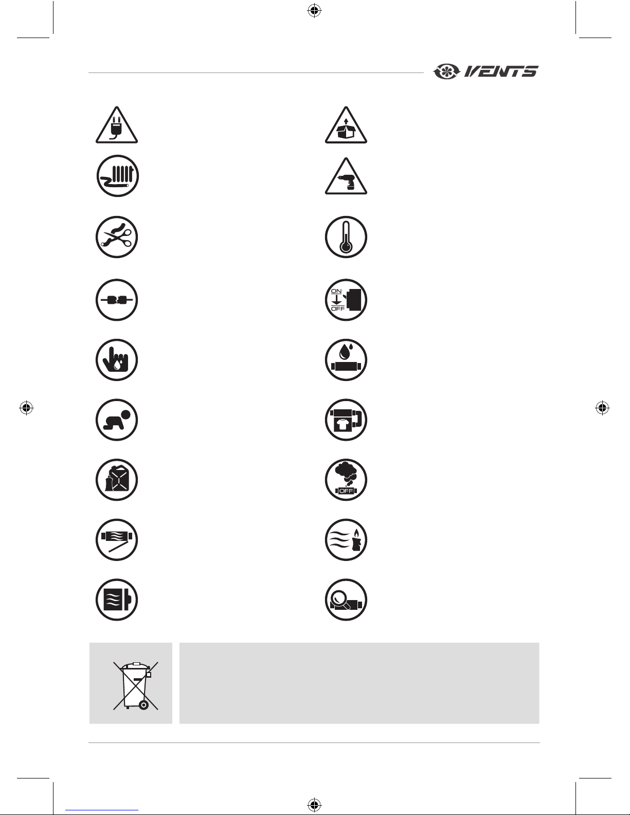
UNIT MOUNTING AND OPERATION SAFETY PRECAUTIONS
• Disconnect the unit from power mains prior
to any installation operations.
• Unpack the unit with care.
• Do not lay the power cable of the unit in
close proximity to heating equipment.
• While installing the unit follow the safety
regulations specic to the use of electric
tools.
• Do not change the power cable length at
your own discretion.
Do not bend the power cable.
Avoid damaging the power cable.
Do not put any foreign objects on the power
cable.
• Do not operate the unit outside the
temperature range stated in the user's
manual.
Do not operate the unit in aggressive or
explosive environments.
• Do not use damaged equipment or cables
when connecting the unit to power mains.
• Disconnect the unit from power mains
prior to any technical maintenance.
• Do not touch the unit controls with wet
hands.
Do not carry out the installation and
maintenance operations with wet hands.
• Do not wash the unit with water.
Protect the electric parts of the unit
against ingress of water.
• Do not allow children to operate the unit. • Use the unit only for its intended purpose.
• Do not store any explosive or highly
ammable substances in close proximity to
the unit.
• When the unit generates unusual sounds,
odour or emits smoke disconnect it from
power supply and contact the Seller.
• Do not open the unit during operation.
• Do not direct the air ow produced by
the unit towards open ame or ignition
sources.
• Do not block the air duct when the unit is
switched on.
• In case of continuous operation of the
unit periodically check the security of
mounting.
DO NOT DISPOSE IN DOMESTIC WASTE.
DO NOT DISPOSE OF AS UNSORTED MUNICIPAL WASTE.
V05EN-07.indd 3 28.04.2016 16:22:22
Page 4
www.ventilation-system.com
4
PURPOSE
The VENTS VKM/VKMz/VC centrifugal fans in a metal casing are designed for ventilation of domestic, public
and manufacturing premises heated during winter.
The transported air temperature must be within the limits stated in the "Technical data" section.
The fan is designed for horizontal or vertical mounting in an air duct and is used both for supply and
exhaust ventilation.
The unit is rated for continuous operation.
THE UNIT MAY NOT BE OPERATED BY CHILDREN OR PERSONS WITH
REDUCED PHYSICAL, MENTAL OR SENSORY CAPACITIES, OR LACKING THE
APPROPRIATE TRAINING.
THE UNIT MUST BE INSTALLED AND CONNECTED ONLY BY PROPERLY
QUALIFIED PERSONNEL AFTER THE APPROPRIATE BRIEFING.
THE CHOICE OF UNIT INSTALLATION LOCATION MUST PREVENT
UNAUTHORIZED ACCESS BY UNATTENDED CHILDREN.
Transported air must not contain any ammable or explosive mixtures, evaporation of chemicals, sticky
substances, brous materials, coarse dust, soot and oil particles or environments favourable for the formation
of hazardous substances (toxic substances, dust, pathogenic germs).
DELIVERY SET
Fan 1 item
Outer mounting bracket for VKM, VKMC, VKM Q, VKMz fans 2 items
Outer mounting bracket for VKM E fans 1 item
User's manual 1 item
Packing box 1 item
V05EN-07.indd 4 28.04.2016 16:22:22
Page 5
5
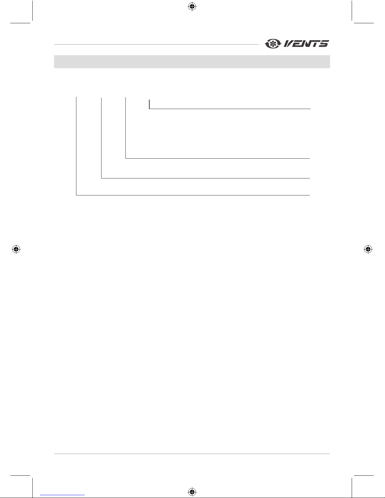
DESIGNATION KEY
Exhaust spigot diamEtEr
100; 125; 150; 200; 250; 315; 355; 400; 450 mm
Options:
Q - equipped with a low-watt motor
E - equipped with an energy-saving motor
Un - speed controller and temperature controller
P - speed controller
R - 0.4 m power cord with the C14 connector
S - increased capacity
Fan name:
VKM - inline centrifugal fan in a metal casing
VKMz - inline centrifugal fan in a galvanized steel casing
VC-VK - inline centrifugal extract fan for outside mounting
VC-PK - inline centrifugal supply fan for mounting into air duct
VC-PN - inline centrifugal supply fan for outside mounting
VC-VN - inline centrifugal extract fan for outside mounting
VCz-VN - inline centrifugal extract fan for outside mounting in a galvanized steel casing
X X X X
DESIGNATION KEY
VKM 150 - inline centrifugal fan in a metal casing for mounting into Ø150 mm air duct.
VKMS 315 - inline centrifugal fan in a metal casing with increased capacity for mounting into Ø315 mm air
duct.
VKM 250 Un - inline centrifugal fan in a metal casing for mounting into Ø250 mm air duct with control logic
based on temperature sensor readings, equipped with an external temperature sensor.
VKMz 200 - inline centrifugal fan in a galvanized steel casing for mounting into Ø200 mm air duct.
VKMz 160P - inline centrifugal fan in a galvanized steel casing for mounting into Ø160 mm air duct with
smooth speed control function.
VC-VK 250 - inline centrifugal extract fan for mounting into Ø250 mm air duct.
VC-PK 125 - inline centrifugal supply fan for mounting into Ø125 mm air duct.
VC-PN 100 - inline centrifugal supply fan for outdoor mounting into Ø100 mm air duct.
VC-VN 315 - inline centrifugal extract fan for outside mounting into Ø315 mm air duct.
VCz-VN 150 - inline centrifugal extract fan in a galvanized steel casing for outside mounting into Ø150 mm
air duct.
V05EN-07.indd 5 28.04.2016 16:22:22
Page 6
www.ventilation-system.com
6
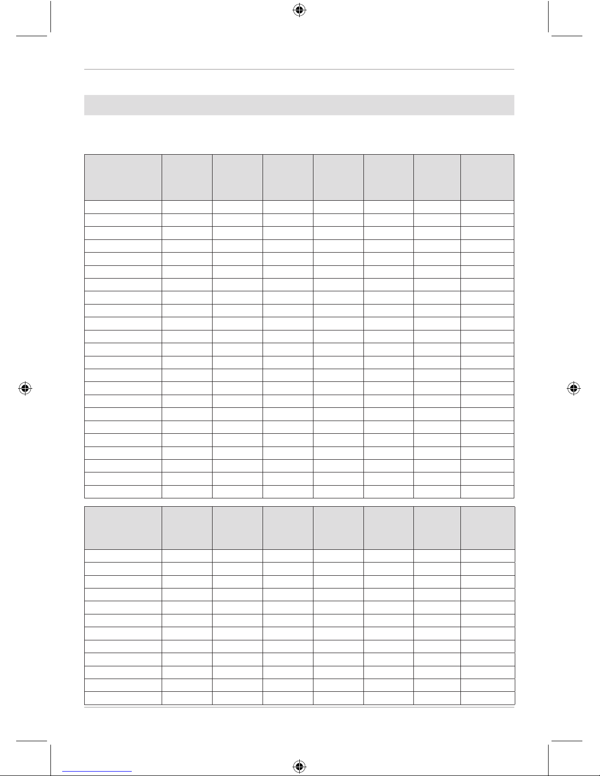
TECHNICAL DATA
Permitted deviation of mains voltage: ±10 % of the rated voltage.
The fan must be grounded.
Ingress Protection Rating IPX4.
Fan model
Voltage,
50 Hz [V]
Power [W] Current [A]
Air capacity
[m3/h], max
RPM
Noise level
at 3 m
[dB(A)]
Trans por ted
air
temperature
[°C]
VKM 100 E 1~230 27 0.13 180 2745 32 -25 +55
VKM 100 Q 1~230 60 0.37 210 2620 36 -25 +55
VKM 100 1~230 73 0.32 270 2830 47 -25 +55
VKM 125 E 1~230 27 0.13 240 2780 32 -25 +55
VKM 125 Q 1~230 60 0.37 255 2535 36 -25 +55
VKM 125 1~230 75 0.33 355 2800 47 -25 +55
VKM 150 Q 1~230 75 0.33 470 2515 46 -25 +55
VKM 150 1~230 98 0.43 55 2705 47 -25 +45
VKMS 150 1~23 0 116 0.52 645 2625 50 -25 +55
VKM 160 Q 1~230 73 0.33 470 2500 46 -25 +55
VKM 160 1~230 98 0.43 555 2660 47 -25 +55
VKMS 160 1~23 0 115 052 645 2650 50 -25 +55
VKM 200 1~230 154 0.67 950 2375 48 -25 +50
VKMS 200 1~23 0 193 0.84 1100 2780 51 -25 +45
VKM 200 E 1~230 95 0.47 780 1950 39 -25 +55
VKM 250 Q 1~230 158 0.69 1190 2315 52 -25 +50
VKM 250 1~230 194 0.85 1310 2790 52 -25 +50
VKM 250 E 1~230 95 0.47 900 2050 44 -25 +55
VKM 315 1~230 171 0.77 1400 2600 52 -25 +50
VKMS 315 1~23 0 296 1.34 1880 2720 54 -25 +45
VKM 355 Q 1~230 233 1.06 2210 1375 58 -25 +45
VKM 400 1~230 460 2.23 3050 1370 61 -25 +80
VKM 450 1~230 665 2.89 5260 1265 65 -25 +70
Fan model
Voltage,
50 Hz [V]
Power [W] Current [A]
Air capacity
[m3/h]
RPM
Noise level
at 3 m
[dB(A)]
Trans por ted
air
temperature
[°C]
VKMz 100 Q
1~230 60 0.37 195 2670 35 -25 +55
VKMz 100
1~230 72 0.32 250 2820 46 -25 +55
VKMz 125 Q
1~230 60 0.37 230 2605 35 -25 +55
VKMz 125
1~230 78 0.34 330 2820 46 -25 +55
VKMz 150
1~230 75 0.33 455 2770 46 -25 +55
VKMz 160
1~230 78 0.34 455 2760 46 -25 +55
VKMz 200 Q
1~230 139 0.61 840 2790 48 -25 +55
VKMz 200
1~230 157 0.69 1000 2740 50 -25 +55
VKMz 250 Q
1~230 134 0.59 980 2785 51 -25 +55
VKMz 250
1~230 152 0.66 1070 2785 52 -25 +55
VKMz 315 Q
1~230 1513 0.66 1330 2680 52 -25 +55
VKMz 315
1~230 185 0.81 1540 2730 53 -25 +55
V05EN-07.indd 6 28.04.2016 16:22:22
Page 7
7
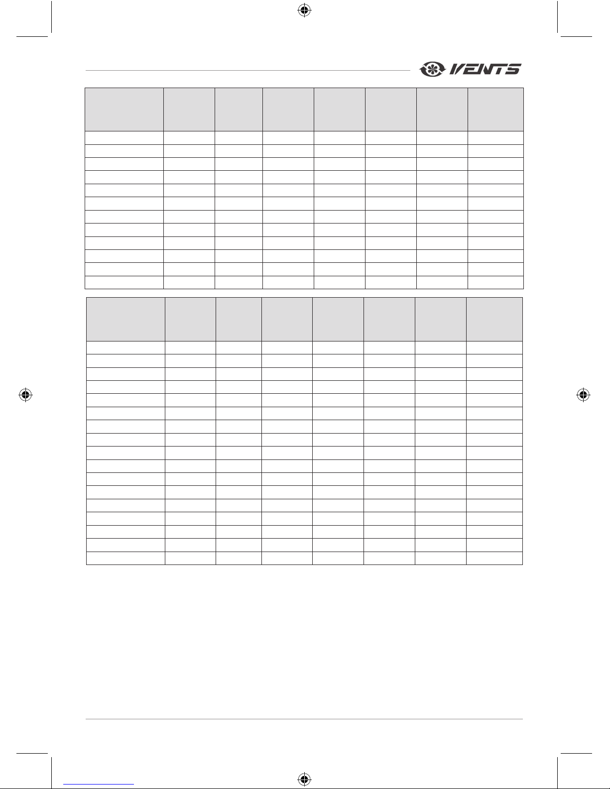
Fan model
Voltage,
50 Hz [V]
Power [W] Current [A]
Air capacity
[m3/h], max
RPM
Noise level
at 3 m
[dB(A)]
Trans por ted
air
temperature
[°C]
VC 100 Q 1~230 60 0.37 210 2620 36 -25 +55
VC 10 0 1~230 73 0. 32 270 2830 47 -25 +55
VC 125 Q 1~230 60 0.37 255 2535 36 -25 +55
VC 125 1~2 30 75 0.33 355 2800 47 -25 +55
VC 150 1~230 98 0.43 555 2705 47 -25 +55
VC 16 0 1~230 98 0.43 555 2660 47 -25 +55
VC 200 1~230 154 0.67 950 2375 48 -25 +50
VCS 200 1~230 193 0.84 110 0 2780 51 -25 +45
VC 250 Q 1~230 15 8 0.69 1190 2315 52 -25 +50
VC 250 1~230 194 0.85 1310 2790 52 -25 +50
VC 315 1~230 171 0.77 14 00 2600 52 -25 +50
VCS 315 1~230 296 1.34 1880 2720 54 -25 +45
Fan model
Voltage,
50 Hz [V]
Power [W] Current [A]
Air capacity
[m3/h], max
RPM
Noise level
at 3 m
[dB(A)]
Trans por ted
air
temperature
[°C]
VCz 100Q -VN 1~230 60 0.37 195 2670 35 -25 +55
VCz 100-VN 1~2 30 72 0.32 250 2820 46 -25 +55
VC z 125Q -VN 1~230 60 0.37 230 2605 35 -25 +55
VC z 125 -VN 1~2 30 78 0.34 330 2820 46 -25 +55
VC z 150 -VN 1~23 0 75 0.33 455 2770 46 -25 +55
VCSz 150-V N 1~2 30 97 0.43 720 2760 46 -25 +55
VCz 160-VN 1~23 0 78 0.34 455 2760 46 -25 +55
VCSz 160-VN 1~23 0 97 0.43 720 2765 46 -25 +55
VCz 200Q-VN 1~230 139 0.61 840 2790 48 -25 +50
VCz 200 -VN 1~230 157 0.69 1000 2740 50 -25 +50
VCSz 200 -VN 1~2 30 193 0.84 1150 2780 51 -25 +50
VCz 250Q-VN 1~230 13 4 0.59 980 2785 51 -25 +50
VCz 250-VN 1~230 152 0.66 1070 2765 52 -25 +50
VCSz 250-VN 1~2 30 175 0.77 118 5 2745 52 -25 +50
VC z 315Q -VN 1~230 151 0.66 133 0 2680 53 -25 +50
VC z 315-V N 1~230 185 0.81 154 0 2730 53 -25 +50
VCSz 315 -VN 1~230 270 1.18 1755 2730 53 -25 +50
The unit design is constantly being improved, so some models can slightly dier from those ones
described in this manual.
V05EN-07.indd 7 28.04.2016 16:22:22
Page 8
www.ventilation-system.com
8
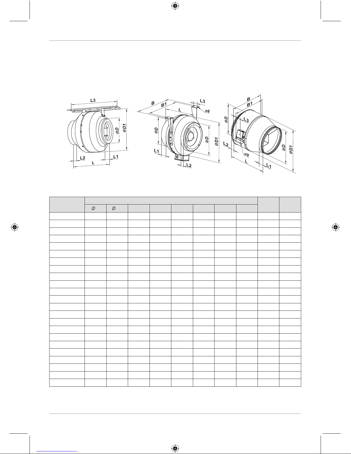
OVERALL AND CONNECTING DIMENSIONS
VKM 100 - 125 E VKM 100 - 315 VKM 355 - 450
Fig. 1 Fig. 2 Fig. 3
Model
Dimensions [mm]
Weight
[kg]
Fig. no.
D D1
B B1 L L1 L2 L3
VKM 100 E 100 204 - - 195 20 20 258 2.1 1
VKM 100 Q 98 254 298 258 205 20 25 30 3.45 2
VKM 100 98 254 298 258 205 20 25 30 3.45 2
VKM 125 E 125 204 - - 195 20 20 258 2.1 1
VKM 125 Q 123 254 298 258 205 20 25 30 3.58 2
VKM 125 123 254 298 258 205 20 25 30 3.58 2
VKM 150 Q 149 304 349 309 200 20 25 30 3.65 2
VKM 150 149 304 349 309 220 25 25 30 3.65 2
VKMS 150 149 340 386 346 226 20 20 40 4.7 2
VKM 160 Q 159 304 349 309 200 20 25 30 3.65 2
VKM 160 159 304 357 317 220 25 25 30 3.65 2
VKMS 160 159 340 386 346 226 20 20 40 4.7 2
VKM 200 198 344 390 350 240 25 29 40 5.7 2
VKMS 200 198 344 390 350 250 25 29 40 5.85 2
VKM 200 E 198 344 390 350 250 25 29 40 6.1 2
VKM 250 Q 248 344 390 350 249 25 31 40 5.1 2
VKM 250 248 344 390 350 249 25 31 40 5.1 2
VKM 250 E 248 344 390 350 249 25 31 40 6.1 2
VKM 315 314 404 454 414 260 25 40 40 7.3 2
VKMS 315 314 404 454 414 288 25 40 40 7.83 2
VKM 355 Q 353 460 522 522 506 60 60 70 18.8 3
VKM 400 398 570 663 634 570 60 60 70 25.1 3
VKM 450 448 608 700 670 644 60 60 80 27.26 3
V05EN-07.indd 8 28.04.2016 16:22:23
Page 9

9
VKMz 100 - 315
Model
Dimensions [mm]
Weight
[kg]
D D1
B B1 L L1 L2 L3
VKMz 100 Q 98 237 253 293 202 23 22 30 3.16
VKMz 100 98 237 253 293 202 23 22 30 3.16
VKMz 125 Q 123 237 253 293 202 23 22 30 3.16
VKMz 125 123 237 253 293 202 23 22 30 3.16
VKMz 150 148 278 294 334 200 25 23 30 3.42
VKMz 160 158 278 294 334 200 25 23 30 3.44
VKMz 200 Q 198 332 340 380 245 25 29 40 5.43
VKMz 200 198 332 340 380 245 25 29 40 5.43
VKMz 250 Q 249 332 340 380 213 25 29 40 5.25
VKMz 250 249 332 340 380 213 25 29 40 5.25
VKMz 315 Q 313 402 410 450 308 33 55 40 6.57
VKMz 315 313 402 410 450 308 33 55 40 6.57
V05EN-07.indd 9 28.04.2016 16:22:23
Page 10
www.ventilation-system.com
10
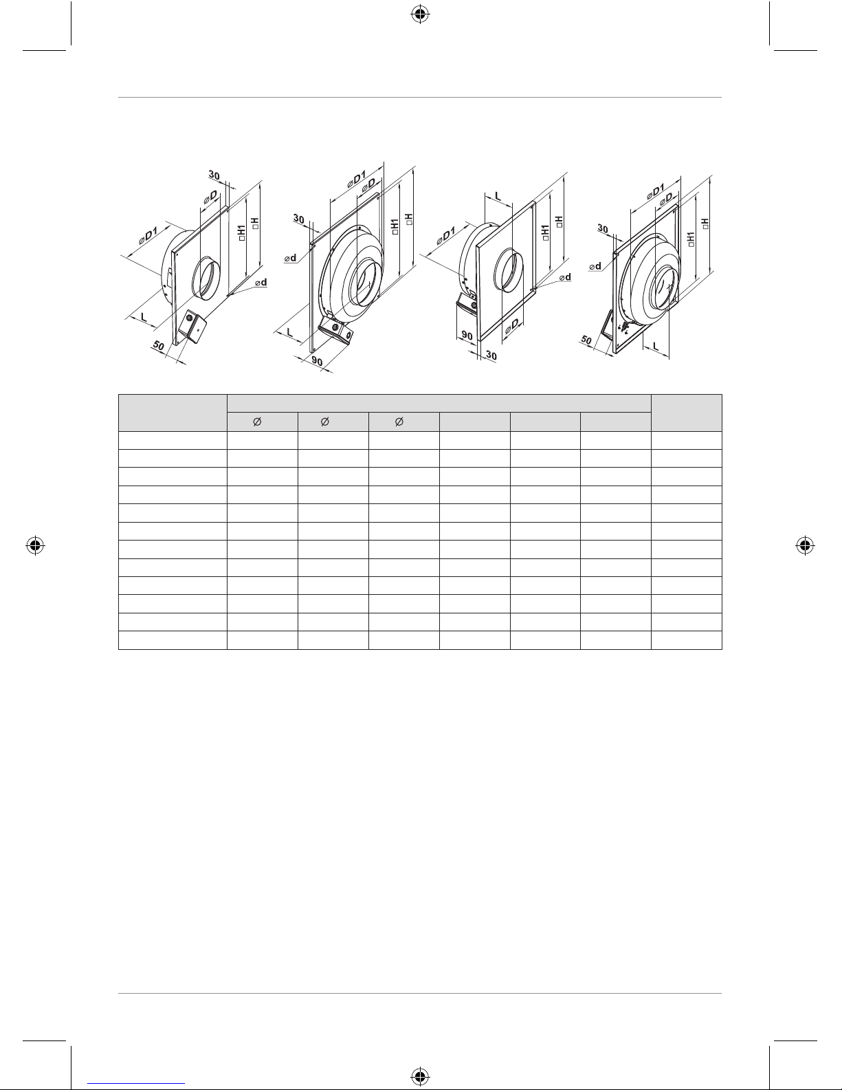
VC-VK VC-VN / VCz-VN VC-PN VC-PK
Model
Dimensions [mm]
Weight [kg]
D D1 d
H H1 L
VC 100 Q 98 249 6,1 310 295 115 3.1
VC 100 98 249 6,1 310 295 115 3.2
VC 125 Q 123 249 6,1 310 295 115 3.1
VC 125 123 249 6,1 310 295 115 3.2
VC 150 149 300 6,1 400 385 115 4.8
VC 160 159 300 6,1 400 385 115 4.9
VC 200 198 339 6,1 400 385 138 6.1
VCS 200 198 339 6,1 400 385 138 6.1
VC 250 Q 248 339 6,1 400 385 138 7.1
VC 250 248 339 6,1 400 385 138 7.2
VC 315 315 399 6,1 460 445 146 7.8
VCS 315 315 399 6,1 460 445 180 7.8
V05EN-07.indd 10 28.04.2016 16:22:23
Page 11
11
DESIGN AND OPERATING LOGIC
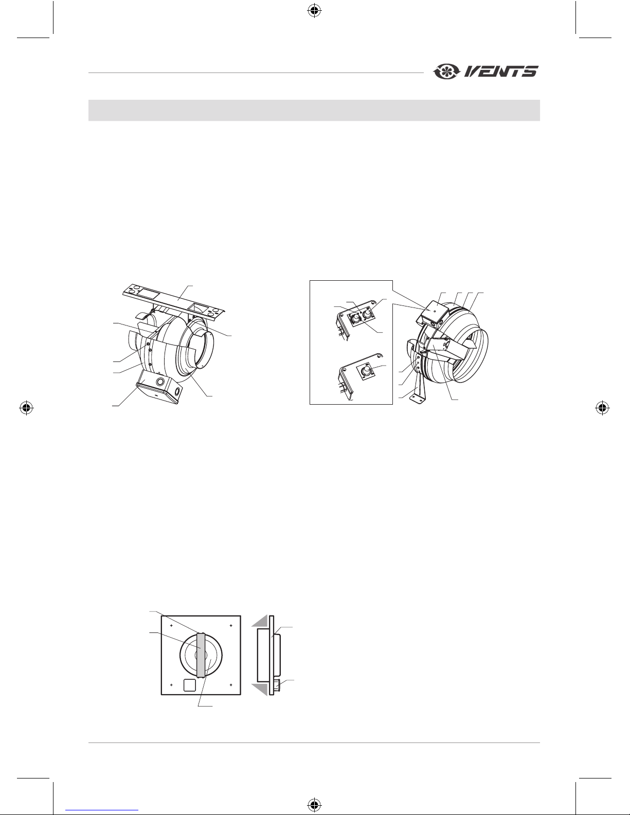
The VKM/VKMz fan (Fig. 4-5) consists of the casing 1, the electric motor attached to the inner xing
bracket 4, the cover 2 that is xed to the casing with screws 3 (the casing spigot diameter and the cover
diameter are equal to the connected air duct diameter), the terminal box 5 that incorporates a terminal block
and a capacitor and enables connection of the fan to single-phase power mains.
The fan models with a temperature and speed controller (Fig. 5) are equipped with a speed control knob
9, a thermostat control knob 10, a fan on/o LED light indicator 11 and a thermostat LED light indicator 12
that are located on the terminal box cover.
The fan models with the speed controller (Fig. 5) are equipped with a speed control knob 9 which is
located on the terminal box 5 cover.
The fan models with a speed controller or with a speed and temperature controller are connected to
power mains through a power cable with a plug.
VKM 100-125 E VKM/VKMz 100 - 315
1
2
3
4
5
6
7
VKM Un / VKMz Un
VKM P / VKMz P
1 23
4
5
6
7
8
9
10
11
12
9
Fig. 4 Fig. 5
1 - casing
2 - cover
3 - screws
4 - inner xing bracket with
an electric motor attached to it
5 - terminal box
6 - outer xing bracket
7 - screws
8 - bolt
9 - fan speed control knob
10 - thermostat control knob
11 - fan on/o LED light indicator
12 - thermostat LED light indicator
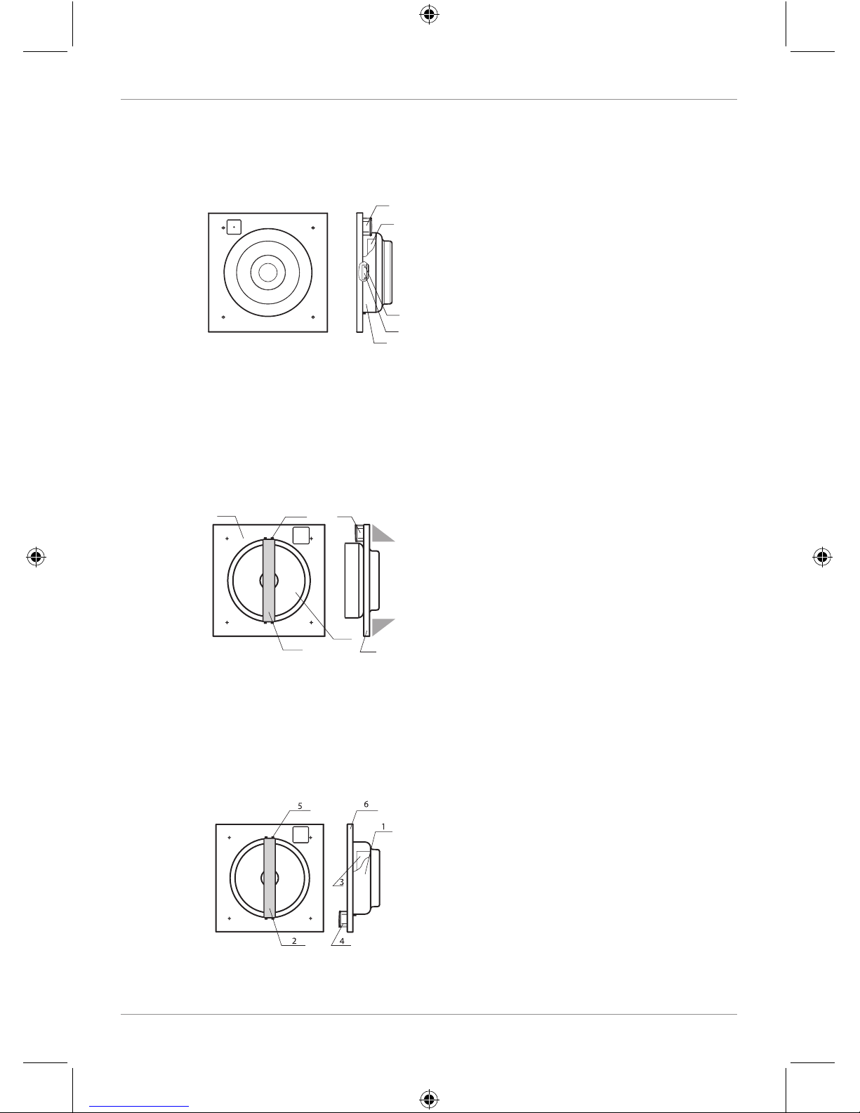
The VC-VK fan (Fig. 6) consists of the casing 1 with the electric motor and impeller 4 xed on the xing
bracket 2.
The xing bracket is attached to the casing with four screws 3.
The terminal box 5 is located on lower part of the casing on intake spigot side to facilitate connection of the
fan to single-phase power mains and placement of the capacitor.
1
5
4
3
2
1 - casing
2 - xing bracket
3 - screws
4 - impeller with an electric motor
5 - terminal box
Fig. 6
V05EN-07.indd 11 28.04.2016 16:22:24
Page 12
www.ventilation-system.com
12
The VC-VN/VCz-VN fan (Fig. 7) consists of the casing 1. The electric motor and the impeller 3 are mounted
inside the casing using the xing bracket 2. The casing is attached to the base plate with screws 5.
The terminal box 4 is located on top of the casing on intake spigot side to facilitate connection of the fan to
single-phase power mains and placement of the capacitor.
4
3
1
2
5
1 - casing
2 - xing bracket
3 - impeller with an electric motor
4 - terminal box
5 - screws
Fig. 7
The VC-PN fan (Fig. 8) consists of the casing 1 with the electric motor and impeller 5 attached to the
xing bracket 2.
The xing bracket is attached to the casing with four screws 3.
The terminal box 6 is located on top of the casing on intake spigot side to facilitate connection of the fan
to single-phase power mains and placement of the capacitor.
4
3
2
5
1
6
1 - casing
2 - xing bracket
3 - screws
4 - base plate
5 - impeller with an electric motor
6 - terminal box
Fig. 8
The VC-PK fan (Fig. 9) consists of the casing 1 with the electric motor and impeller 3 attached to the
xing bracket 2 inside.
The xing bracket 2 is attached to the casing with four screws 5.
The exhaust outlet of the fan is covered with a grille.
The terminal box 4 is located on top of the casing on intake spigot side to facilitate connection of the fan
to single phase power mains and placement of the capacitor.
1 - casing
2 - xing bracket
3 - impeller with an electric motor
4 - terminal box
5 - screws
6 - base plate
Fig. 9
V05EN-07.indd 12 28.04.2016 16:22:24
Page 13
13
MOUNTING
THE UNIT MUST BE MOUNTED BY A QUALIFIED EXPERT ONLY,
PROPERLY TRAINED AND HAVING THE REQUIRED TOOLS AND
MATERIALS.
VKM/VKMz fan
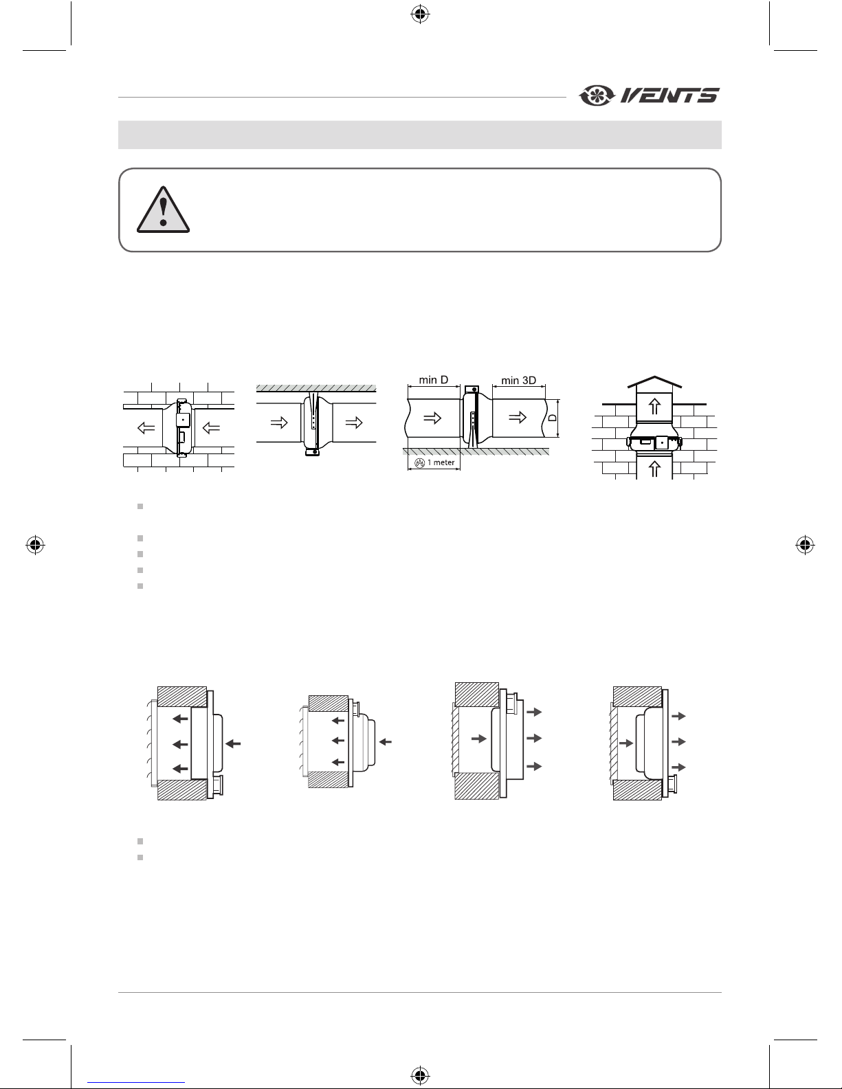
The fans are designed for vertical or horizontal mounting.
Air motion in the system must be in compliance with the direction of the arrow on the fan casing.
Install a hood on the intake spigot side in case of the vertical fan installation.
Provide a straight air duct section at least 1 m long on the intake spigot side in case of horizontal fan
installation with maximum allowable humidity.
Mounting sequence:
remove the bolt from the casing 1 and install the xing brackets in such a way so that the holes on the
xing brackets are aligned with the heads of the screws 3.
Fix the xing brackets on the casing with bolts.
Drill the holes in the mounting surface to match the tment holes of the xing brackets.
Fix the fan with the screws.
Connect the air ducts of the respective size to the fan and x them with clamps.
VC-VK, VC-PN, VC-PK, VC-VN, VCz-VN fan
VC-VK VC-VN / VCz-VN VC-PN VC-PK
Mounting sequence:
Drill the holes in the mounting surface to match the tment holes in the fan basement.
Fix the fan with the screws.
V05EN-07.indd 13 28.04.2016 16:22:24
Page 14
www.ventilation-system.com
14
CONNECTION TO POWER MAINS
DISCONNECT THE UNIT FROM POWER SUPPLY PRIOR TO ANY
OPERATIONS WITH THE UNIT.
CONNECTION OF THE UNIT TO POWER MAINS IS ALLOWED BY A
QUALIFIED ELECTRICIAN WITH A WORK PERMIT FOR THE ELECTRIC
UNITS UP TO 1000 V AFTER CAREFUL READING OF THE PRESENT
USER'S MANUAL.
THE RATED ELECTRICAL PARAMETERS OF THE UNIT ARE GIVEN
ON THE MANUFACTURER'S LABEL. ANY TAMPERING WITH THE
INTERNAL CONNECTIONS IS PROHIBITED AND WILL VOID THE
WARRANTY.
The fan is designed for 230 V/50 Hz single-phase alternating current mains.
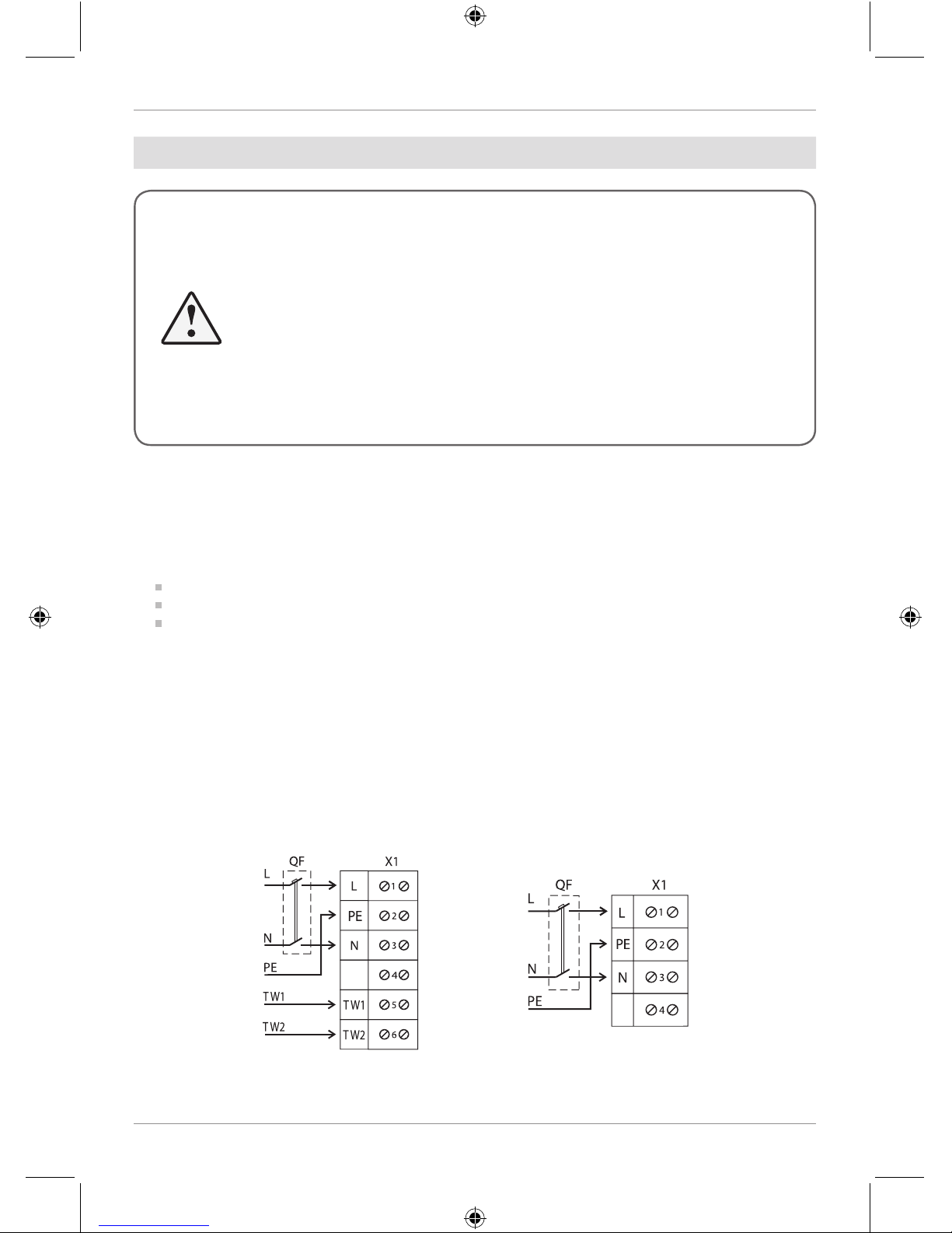
The fan shall be connected to power supply by means of insulated, durable and thermal-resistant cords
(cables, wires) through the external circuit breaker with a thermal-magnetic trip built into the stationary wiring
to disconnect all the power mains phases. The rated current must be not below the rated current consumption
(refer to Technical data). The QF external switch location must ensure free access for quick shutdown of the fan.
The recommended rated current of the circuit breaker:
2 A for the VKMS 315, VKM 355Q, VCS 315 fans
3.15 A for the VKM 400, VKM 450 fans
1 A for all other fans
The recommended wire cross section is 0.75 mm2.
The actual conductor cross-section selection must be based on its type, the maximum permissible heating,
insulation, length and installation method (in the air, pipes or inside walls).
Connect the cables to the terminal block incorporated inside the terminal box located on the fan casing in
compliance with the fan wiring diagram and the terminal designation.
The terminal designations are shown on the sticker inside the fan casing.
The wiring diagram for the VKM 400, VKM 450 fans is shown in Fig. 10. The wiring diagram for the other fans
is shown in Fig. 11.
The fans with a speed controller and temperature and speed controller (VKM Un, VKMz Un, VKM P, VKMz P)
are designed for connection to single-phase AC power mains 230 V/50 Hz and are equipped with a power cord
and a plug (supplied connected to the terminal block).
Fig. 10 Fig. 11
~230 V
50 Hz
~230 V
50 Hz
V05EN-07.indd 14 28.04.2016 16:22:24
Page 15
15
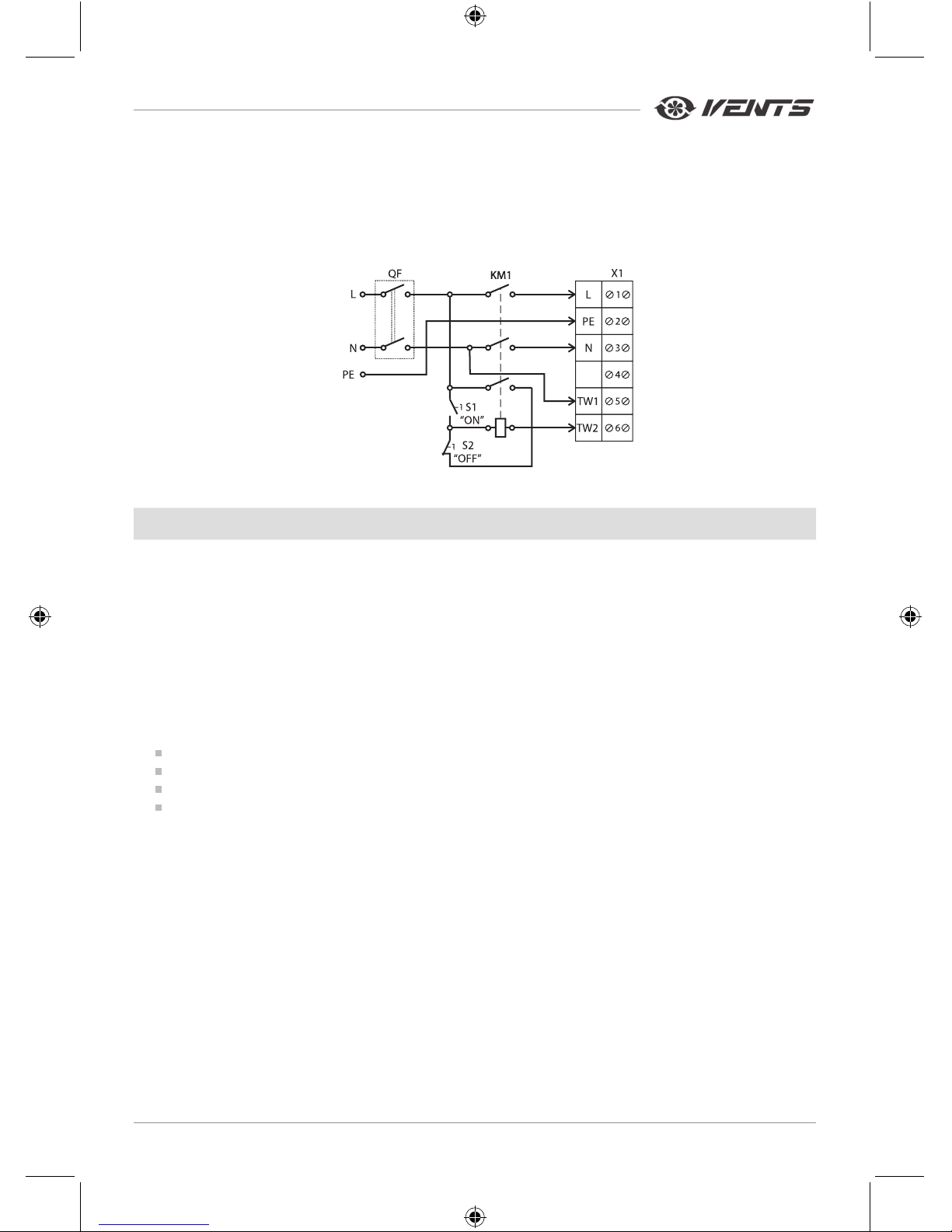
The TW1, TW2 terminals are the electrical leads of the normally closed contact of the motor overheating
protection. Connect the contact in series to power circuit of the magnetic starter coil KM1 that starts the motor
after pressing the S1 button. In case of pressing the S2 button or motor overheating the contact gets broken
and switches the starter coil o to cut power o and stop the motor. The QF circuit breaker, the magnetic
starter KM1, the control knobs S1 and S2 are not included in the delivery and must be installed by the user.
The motor connection example with thermal protecting contacts leaded outside are shown in Fig. 12.
Fig. 12
CONTROL
The VKM P, VKMz P fans with a built-in electronic module
The electronic module is designed for smooth control of fan speed (air ow). The speed is controlled with
the speed control knob 9 (Fig. 5).
The VKM Un, VKMz Un fans with a temperature and speed controller
The controller is designed for air temperature control and fan speed control depending on ambient air
temperature.
The speed is controlled with the speed control knob 9 and the temperature control knob 10 (Fig. 5).
The VKM Un, VKMz Un fans are equipped with an external temperature sensor xed on a 4 m cable.
The cover of the terminal box incorporates the following controls:
speed control knob 9 (Fig. 5)
temperature controller 10 (Fig. 5) to set the thermostat temperature threshold
on/o LED light indicator 11 (Fig. 5)
thermostat LED light indicator 12 (Fig. 5)
Operation algorithm of the VKM Un and VKMz Un fans
Set the thermostat temperature threshold with a thermostat control knob 10. Turn on the fan, then set the
fan speed with the speed control knob 9. The fan on/o light indicator 11 lights up. The controller switches the
fan to the maximum speed (maximum air ow) as the temperature rises and crosses the thermostat setpoint.
The thermostat light indicator 12 glows if the temperature is above the thermostat setpoint. If the temperature
falls 2 °C below the thermostat setpoint, the fan reverts to the preset lower speed. This prevents frequent speed
changeovers during operation with the temperature close to the threshold value. This control logic enables
tracking temperature uctuations and respond to the temperature change with accuracy up to 2 °C. The rate
of the speed switching depends exclusively on the air temperature uctuations.
~230 V
50 Hz
V05EN-07.indd 15 28.04.2016 16:22:24
Page 16
www.ventilation-system.com
16
TECHNICAL MAINTENANCE
DISCONNECT THE UNIT FROM POWER MAINS PRIOR TO ANY
MAINTENANCE OPERATIONS.
Disconnect the fan from power supply prior to maintenance and servicing operations.
The technical maintenance includes periodic cleaning of the surfaces from accumulated dust and dirt. Use
a soft dry brush or a vacuum cleaner to remove dust. The impeller blades require thorough cleaning once in
6 months.
Connection sequence:
VKM/VKMz (Fig. 4, 5)
remove the screws 3 and take o the cover 2.
VC-VK (Fig. 6)
remove the screws 3 and pull out the electric motor-impeller block 4 with the xing bracket 2.
VC-VN/VCz-VN (Fig. 7)
remove the screws 5 and pull out the electric motor-impeller block 3 with the xing bracket 2.
VC-PN (Fig. 8)
remove the screws 3 and pull the xing bracket 2 with the impeller 5 out of the casing.
VC-PK (Fig. 9)
remove the screws 5 and pull the xing bracket 2 with the impeller 3 out of the casing 1.
Clean the impeller blades with a soft cloth wetted in mild water detergent solution. Avoid liquid dripping
on the motor.
STORAGE AND TRANSPORTATION REGULATIONS
Store the unit in the manufacturer's original packing box in a dry closed ventilated premise with
temperature range from +5 °C to + 40 °C. Storage environment must not contain aggressive vapours and
chemical mixtures provoking corrosion, insulation and sealing deformation.
The unit can be transported in the original packing by any mode of transport without limitation provided
proper protection against precipitation and mechanical damage.
Use suitable hoist machinery for handling and storage operations to prevent possible damage to the unit.
Follow the handling requirements applicable for the particular type of cargo.
Avoid sharp blows, scratches or rough handling during loading and unloading.
Do not expose the unit to sudden changes in temperature. Such changes can lead to condensation of
moisture inside the unit and performance disturbance when the unit is switched on. Prior to the initial powerup after transportation at subzero temperatures allow the unit to warm up at room temperature for at least
2hours.
V05EN-07.indd 16 28.04.2016 16:22:25
Page 17
17
MANUFACTURER’S WARRANTY
The manufacturer hereby warrants normal operation of the unit for 24 months after the retail sale date provided the user's
observance of the transportation, storage, mounting and operation regulations.
Should any malfunctions occur in the course of the unit operation through the Manufacturer's fault during the guaranteed
period of operation the user is entitled to elimination of faults by the manufacturer by means of warranty repair at the factory
free of charge.
The warranty repair shall include work specic to elimination of faults in the unit operation to ensure its intended use by
the user within the guaranteed period of operation. The faults are eliminated by means of replacement or repair of the unit
components or a specic part of such unit component.
The warranty repair does not include:
• routine technical maintenance
• unit installation / dismantling
• unit setup
To benet from warranty repair the user must provide the unit, the user's manual with the purchase date stamp and the
payment document certifying the purchase.
The unit model must comply with the one stated in the user's manual.
Contact the Seller for warranty service.
The manufacturer's warranty does not apply to the following cases:
• User's failure to submit the unit with the entire delivery package as stated in the user's manual including submission
with missing component parts previously dismounted by the user.
• Mismatch of the unit model and the brand name with the information stated on the unit packing and in the user's
manual.
• User's failure to ensure timely technical maintenance of the unit.
• External damage to the unit casing (excluding external modications as required for installation) and internal
components caused by the user.
• Redesign or engineering changes to the unit.
• Replacement and use of any assemblies, parts and components not approved by the manufacturer.
• Unit misuse.
• User's violation of the unit installation regulations.
• User's violation of the unit control regulations.
• Unit connection to the power mains with a voltage dierent from the one stated in the user's manual.
• Unit breakdown due to voltage surges in the power mains.
• Discretionary repair of the unit by the user.
• Unit repair by any persons without the manufacturer's authorization.
• Expiration of the unit warranty period.
• User's violation of the unit transportation regulations.
• User's violation of the unit storage regulations.
• Wrongful actions against the unit committed by third parties.
• Unit breakdown due to circumstances of insuperable force (re, ood, earthquake, war, hostilities of any kind,
blockades).
• Missing seals if provided by the user's manual.
• Failure to submit the user's manual with the unit purchase date stamp.
• Missing payment document certifying the unit purchase.
FOLLOWING THE REGULATIONS STIPULATED HEREIN WILL ENSURE A LONG AND
TROUBLE-FREE OPERATION OF THE UNIT.
USERS' WARRANTY CLAIMS SHALL BE SUBJECT TO REVIEW ONLY UPON
PRESENTATION OF THE UNIT, THE PAYMENT DOCUMENT AND THE USER'S
MANUAL WITH THE PURCHASE DATE STAMP.
V05EN-07.indd 17 28.04.2016 16:22:25
Page 18
www.ventilation-system.com
18
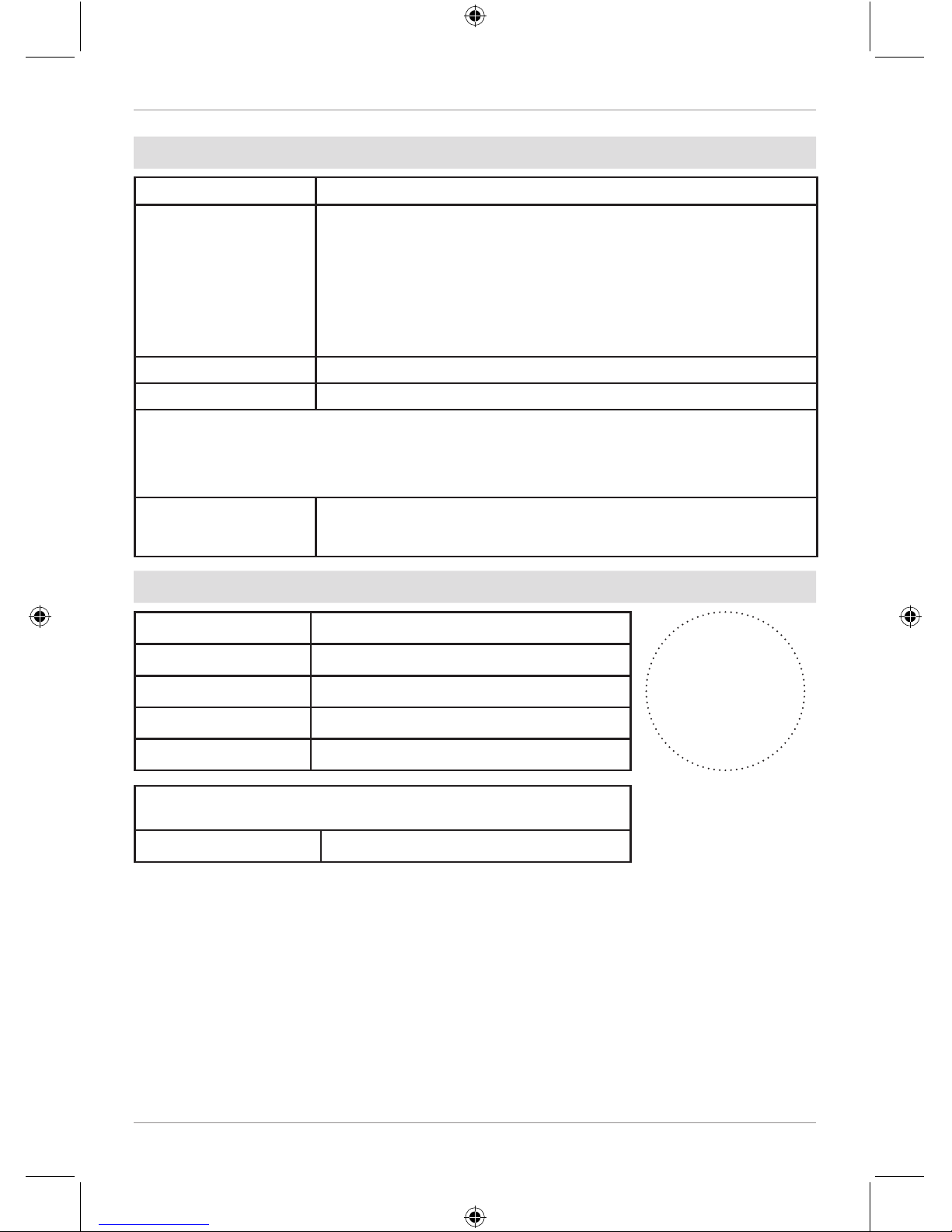
ACCEPTANCE CERTIFICATE
Unit type Centrifugal inline fan
Model
VKM ______________
VKMz _____________
VC ________________
Serial Number
Manufacture Date
is compliant with the technical specications and is hereby declared ready for service. We hereby declare that the product
complies with the essential protection requirements of Electromagnetic Council Directive 2004/108/EC, 89/336/EEC and
Low Voltage Directive 2006/95/EC, 73/23/EEC and CE-marking Directive 93/68/EEC on the approximation of the laws of
the Member States relating to electromagnetic compatibility.
This certicate is issued following test carried out on samples of the product referred to above.
Quality Inspector's
Stamp
SELLER INFORMATION
Seller
Address
Phone Number
E-mail
Purchase Date
This is to certify acceptance of the complete unit delivery with the user's
manual. The warranty terms are acknowledged and accepted.
Customer's Signature
Seller's Stamp
V05EN-07.indd 18 28.04.2016 16:22:25
Page 19
19
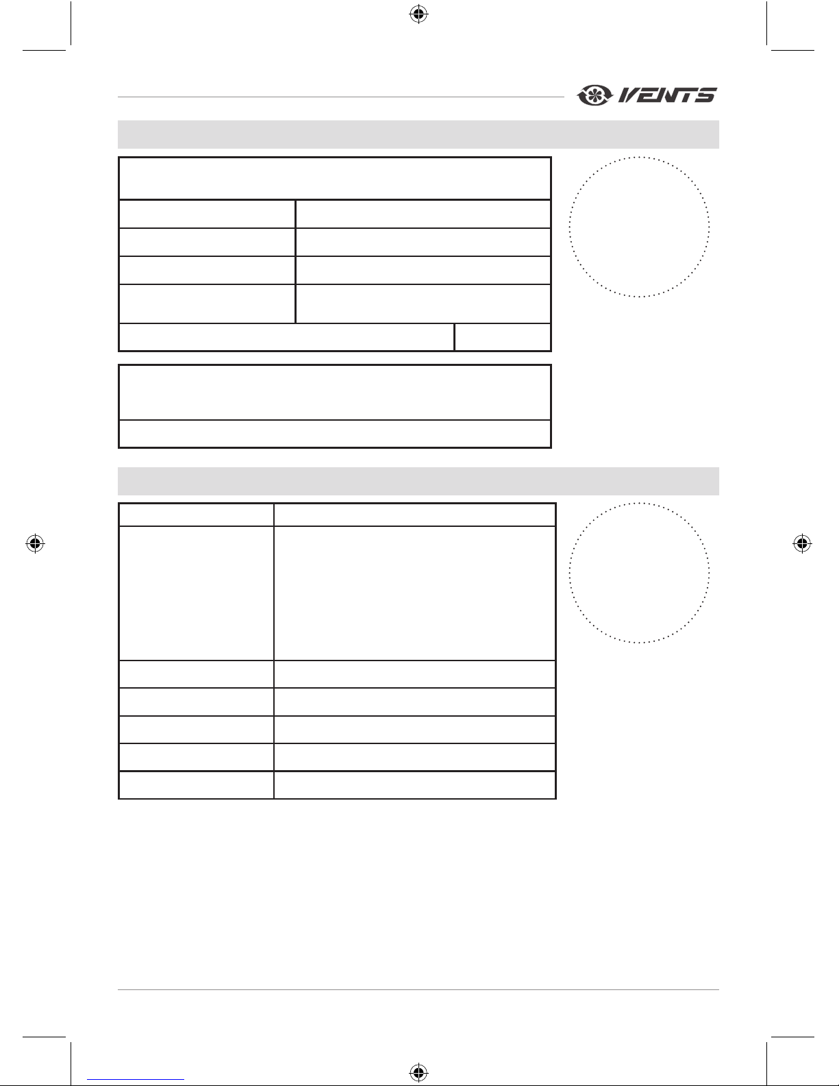
INSTALLATION CERTIFICATE
Installation Company
Stamp
The unit has been connected to power mains pursuant to the requirements
stated in the present user's manual.
Company Name
Address
Phone Number
Installation Technician's
Full Name
Installation Date: Signature:
The unit has been installed in accordance with the provisions of all the
applicable local and national construction, electrical and technical codes
and standards. The unit operates normally as intended by the manufacturer.
Signature:
WARRANTY CARD
Unit type Centrifugal inline fan
Model
VKM ______________
VKMz _____________
VC ________________
Serial Number
Manufacture Date
Purchase Date
Warranty Period
Seller
Seller's Stamp
V05EN-07.indd 19 28.04.2016 16:22:25
Page 20

V05EN-07
V05EN-07.indd 20 28.04.2016 16:22:25
 Loading...