

Vents TwinFresh Comfo RA1-25-2, TwinFresh Comfo RA-35, TwinFresh Comfo SA-35, TwinFresh Comfo SA1-35-2, TwinFresh Comfo RA-35-2 User Manual
...Page 1
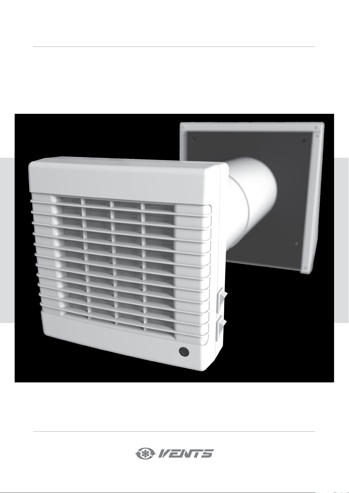
USER’S MANUAL
TwinFresh Comfo
RA1-25
RA1-25-2
SA-35
SA-35-2
SA1-35
SA1-35-2
RA-35
RA-35-2
RA1-35
RA1-35-2
RA-50
RA-50-2
RA1-50
RA1-50-2
RA-85
RA-85-2
RA1-85
RA1-85-2
Single-room reversible energy
recovery ventilator
Page 2
TwinFresh Comfo
CONTENTS
Safety requirements ....................................................................................................................................2
Purpose ...............................................................................................................................................................4
Delivery set .......................................................................................................................................................4
Designation key .............................................................................................................................................5
Technical data .................................................................................................................................................5
Unit design and operating principle ................................................................................................8
Mounting and set-up ..............................................................................................................................10
Connection to power mains ..............................................................................................................15
Ventilator control .......................................................................................................................................17
Technical maintenance ..........................................................................................................................19
Troubleshooting .........................................................................................................................................21
Storage and transportation regulations ...................................................................................... 21
Manufacturer’s warranty ....................................................................................................................... 22
Acceptance certificate ........................................................................................................................... 23
Seller information ......................................................................................................................................23
Installation certificate ..............................................................................................................................23
Warranty card ...............................................................................................................................................23
The user’s manual consisting of the technical details, operating instructions and technical specification applies to the installation and mounting of
the single-room energy regeneration reversible ventilator TwinFresh Comfo (hereinafter referred to as «ventilator» or «unit» as mentioned in the «Safety
Requirements» and «Manufacturer’s Warranty» sections as well as in warnings and information blocks).
SAFETY REQUIREMENTS
• Read the user’s manual carefully prior to installing and operating the unit.
• Fulfil the user’s manual requirements as well as the provisions of all the applicable local and national construction, electrical and technical norms and
standards.
• The warnings contained in the user’s manual must be considered most seriously since they contain vital personal safety information.
• Failure to follow the rules and safety precautions noted in this user’s manual may result in an injury or unit damage.
• After a careful reading of the manual, keep it for the entire service life of the unit.
• While transferring the unit control the user’s manual must be turned over to the receiving operator.
Symbol legend:
WARNING!
DO NOT!
UNIT MOUNTING AND OPERATION SAFETY PRECAUTIONS
• Disconnect the unit from power mains prior to
any installation operations.
• Unpack the unit with care.
• Do not lay the power cable of the unit in close
proximity to heating equipment.
• Do not change the power cable length at your
own discretion.
• Do not bend the power cable.
• Avoid damaging the power cable.
• Do not put any foreign objects on the power
cable.
2
• While installing the unit follow the safety
regulations specific to the use of electric tools.
• The unit must be grounded!
www.ventilation-system.com
Page 3
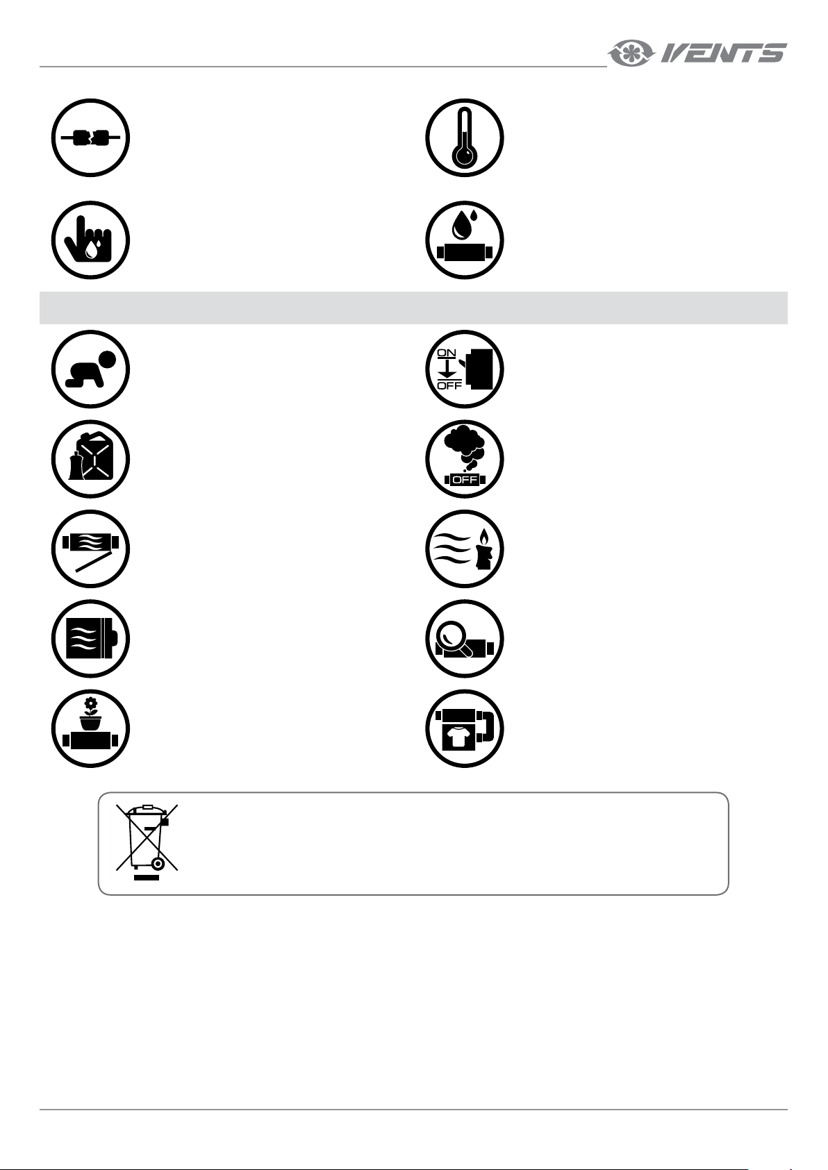
• Do not use damaged equipment or cables
when connecting the unit to power mains.
• Do not operate the unit outside the
temperature range stated in the user's manual.
• Do not operate the unit in aggressive or
explosive environments.
• Do not touch the unit controls with wet hands.
• Do not carry out the installation and
maintenance operations with wet hands.
UNIT MOUNTING AND OPERATION SAFETY PRECAUTIONS
• Do not allow children to operate the unit.
• Do not store any explosive or highly flammable
substances in close proximity to the unit.
• Do not open the unit during operation.
• Do not wash the unit with water.
• Protect the electric parts of the unit against
ingress of water.
• Disconnect the unit from power mains prior to
any technical maintenance.
• When the unit generates unusual sounds, odour
or emits smoke disconnect it from power supply
and contact the Seller.
• Do not direct the air flow produced by the unit
towards open flame or ignition sources.
• Do not block the air duct when the unit is
switched on.
• Do not sit on the unit and avoid placing foreign
objects on it.
THE PRODUCT MUST BE COLLECTED SEPARATELY AT THE END OF SERVICE LIFE.
DO NOT DISPOSE OF AS UNSORTED MUNICIPAL WASTE.
• In case of continuous operation of the unit
periodically check the security of mounting.
• Use the unit only for its intended purpose.
www.ventilation-system.com
3
Page 4
TwinFresh Comfo
PURPOSE
The ventilator is designed to ensure continuous mechanical air exchange in flats, cottages, hotels, cafes and other domestic and public premises.
The ventilator is equipped with a ceramic regenerator that enables supply of fresh filtered air heated by means of extract air heat energy
regeneration.
The ventilator is designed for wall flush mounting.
The telescopic air duct design enables its installation in the walls with various thickness, see the table below:
Wall thickness Ventilator model
300 mm - 570 mm (11 13/16’’ - 22 7/16”) RA1-25
120 mm - 500 mm (4 3/4’’ - 19 11/16”) RA1-25-2
SA-35
SA1-35
RA-35
250 mm - 470 mm (9 13/16’’ - 18 1/2”)
120 mm - 430 mm (4 3/4’’ - 16 15/5”)
120 mm - 470 mm (4 3/4’’ - 18 1/2”)
RA1-35
RA-50
RA1-50
RA-85
RA1-85
SA-35-2
SA1-35-2
RA-35-2
RA1-35-2
RA-50-2
RA1-50-2
RA-85-2
RA1-85-2
The unit is rated for continuous operation.
Transported air must not contain any flammable or explosive mixtures, evaporation of chemicals, sticky substances, fibrous materials, coarse dust,
soot and oil particles or environments favourable for the formation of hazardous substances (toxic substances, dust, pathogenic germs).
THE UNIT MAY NOT BE OPERATED BY CHILDREN OR PERSONS WITH REDUCED PHYSICAL,
MENTAL OR SENSORY CAPACITIES, OR LACKING THE APPROPRIATE TRAINING.
THE UNIT MUST BE INSTALLED AND CONNECTED ONLY BY PROPERLY QUALIFIED PERSONNEL
AFTER THE APPROPRIATE BRIEFING.
THE CHOICE OF UNIT INSTALLATION LOCATION MUST PREVENT UNAUTHORIZED ACCESS BY
UNATTENDED CHILDREN.
DELIVERY SET
Name Number
Ventilator 1 item
Remote control 1 item
Fastening set 2 packs
User's manual 1 item
Mounting hood installation instruction 1 item
Packing box 1 item
4
www.ventilation-system.com
Page 5
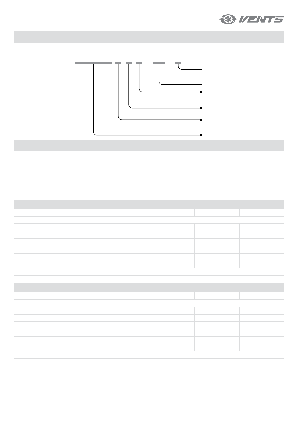
DESIGNATION KEY
TwinFresh Comfo R A 1 - 25 - 2
Ventilation hood model
_ - EH ventilation hood
2 - EH 2 ventilation hood for thin walls
Rated air capacity [m
Front panel modification
_ - decorative grille
1 - flat front panel
Automation type
A - integrated automation and control system
Air duct cross section
R — round
S - square
Comfo Series
TECHNICAL DATA
The ventilator is rated for indoor application with the ambient temperature ranging from -20 °C (-4 °F) up to +50 °C (+122 °F) and relative humidity up to
80 %.
The ventilator is rated as a class I electric appliance.
Hazardous parts access and water ingress protection rating IP24.
The unit design is constantly improved, so some models may slightly differ from the ones depicted herein.
3
/h]
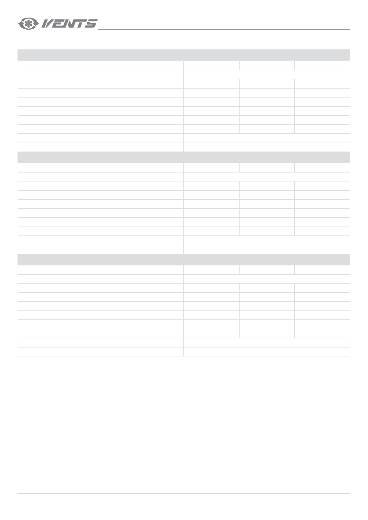
VENTILATOR TECHNICAL DATA
TwinFresh Comfo RA1-25, TwinFresh Comfo RA1-25-2
Speed I II III
Unit voltage [V /50 (60) Hz] 1~100-240
3
Air capacity [m
/h] (CFM) 7 (4) 15 (9) 24 (14)
Power [W] 3.50 3.95 5.32
Current [A] 0.023 0.026 0.036
RPM 1190 1330 2420
Noise level, 1 m [dB(A)] (Sones) 31 (0.9) 35 (1.3) 43 (2.5)
Noise Level, 3 m [dB(A)] (Sones) 22 (0.4) 25 (0.5) 33 (1.1)
Outdoor noise attenuation [dB(A)] (Sones) 16 (0.4)
Heat recovery efficiency up to 85 %
TwinFresh Comfo RA-35, TwinFresh Comfo RA1-35, TwinFresh Comfo RA-35-2, TwinFresh Comfo RA1-35-2
Speed I II III
Unit voltage [V/50 (60) Hz] 1~100-240
3
Air capacity [m
/h] (CFM) 10 (6) 20 (12) 30 (18)
Power [W] 3.93 4.39 5.10
Current [A] 0.023 0.026 0.032
RPM 745 1075 1670
Noise level, 1 m [dB(A)] (Sones) 27 (0.6) 32 (1.0) 38 (2.0)
Noise Level, 3 m [dB(A)] (Sones) 18 (0.4) 23 (0.5) 28 (0.7)
Outdoor noise attenuation [dB(A)] (Sones) 17 (0.4)
Heat recovery efficiency up to 90 %
www.ventilation-system.com
5
Page 6
TwinFresh Comfo
VENTILATOR TECHNICAL DATA
TwinFresh Comfo RA-50, TwinFresh Comfo RA1-50, TwinFresh Comfo RA-50-2, TwinFresh Comfo RA1-50-2
Speed I II III
Unit voltage [V/50 (60) Hz] 1~100-240
3
Air capacity [m
Power [W] 3.80 3.96 5.61
Current [A] 0.024 0.026 0.039
RPM 610 800 1450
Noise level, 1 m [dB(A)] (Sones) 22 (0.4) 29 (0.7) 32 (1.0)
Noise Level, 3 m [dB(A)] (Sones) 13 (0.2) 20 (0.4) 23 (0.5)
Outdoor noise attenuation [dB(A)] (Sones) 18 (0.4)
Heat recovery efficiency up to 90 %
Speed I II III
Unit voltage [V /50 (60) Hz] 1~100-240
Air capacity [m
Power [W] 4.74 6.56 9.65
Current [A] 0.034 0.050 0.071
RPM 1000 1500 2045
Noise level, 1 m [dB(A)] (Sones) 29 (0.8) 35 (1.5) 44 (3.5)
Noise Level, 3 m [dB(A)] (Sones) 19 (0.4) 25 (0.7) 34 (1.4)
Outdoor noise attenuation [dB(A)] (Sones) 18 (0.4)
Heat recovery efficiency up to 90 %
Speed I II III
Unit voltage [V/50 (60) Hz] 1~100-240
Air capacity [m
Power [W] 4.54 5.18 6.10
Current [A] 0.026 0.031 0.037
RPM 851 1330 1715
Noise level, 1 m [dB(A)] (Sones) 28 (0.7) 33 (1.1) 39 (2.0)
Noise Level, 3 m [dB(A)] (Sones) 19 (0.4) 24 (0.5) 29 (0.7)
Outdoor noise attenuation [dB(A)] (Sones) 18 (0.4)
Heat recovery efficiency up to 88 %
/h] (CFM) 14 (8) 28 (16) 54 (32)
TwinFresh Comfo RA-85, TwinFresh Comfo RA-1-85, TwinFresh Comfo RA-85-2, TwinFresh Comfo RA1-85-2
3
/h] (CFM) 36 (21) 59 (35) 85 (50)
TwinFresh Comfo SA-35, TwinFresh Comfo SA1-35, TwinFresh Comfo SA-35-2, TwinFresh Comfo SA1-35-2
3
/h] (CFM) 12 (7) 25 (15) 37 (22)
6
www.ventilation-system.com
Page 7
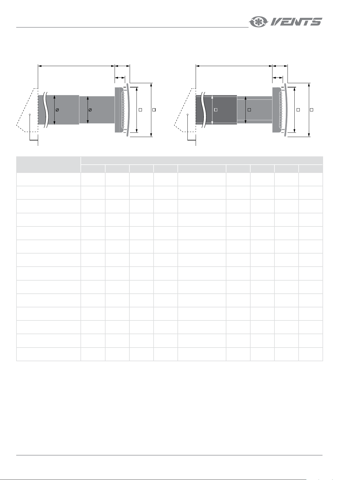
Drawing for ventilators with round
air duct cross section
OVERALL DIMENSIONS OF VENTILATORS
Drawing for ventilators with square
air duct cross section
L
D1 D2 A1
The outer ventilation hood
is presented schematically
Model
TwinFresh Comfo RA1-25 -
TwinFresh Comfo RA1-25-2 -
TwinFresh Comfo RA-35
TwinFresh Comfo RA-35-2
TwinFresh Comfo RA1-35 -
TwinFresh Comfo RA1-35-2 -
TwinFresh Comfo RA-50
TwinFresh Comfo RA-85
TwinFresh Comfo RA-50-2
TwinFresh Comfo RA-85-2
TwinFresh Comfo RA1-50
TwinFresh Comfo RA1-85
TwinFresh Comfo RA1-50-2
TwinFresh Comfo RA1-85-2
TwinFresh Comfo SA-35
TwinFresh Comfo SA-35-2
TwinFresh Comfo SA1-35 -
TwinFresh Comfo SA1-35-2 -
(8 3/8’’)
(8 3/8’’)
(8 3/8’’)
(8 3/8’’)
(8 3/8’’)
(8 3/8’’)
B1
B
L
A2
B
B1
A1
The outer ventilation hood
is presented schematically
Overall dimensions [mm] (inches)
A1 A2 B B1 L D1 D2 C1 C2
213
213
213
213
213
213
205
(8 1/16’’)50(1 15/16’’)
205
(8 1/16’’)50(1 15/16’’)
- -
- -
240
(9 7/16’’)
240
(9 7/16’’)
- -
- -
-
-
240
(9 7/16’’)
240
(9 7/16’’)
- -
- -
240
(9 7/16’’)
240
(9 7/16’’)
80
(3 1/8’’)
80
(3 1/8’’)
86
(3 3/8’’)
86
(3 3/8’’)
86
(3 3/8’’)
86
(3 3/8’’)
-
-
57
(2 1/4’’)
57
(2 1/4’’)
-
-
65
(2 9/16’’)
65
(2 9/16’’)
-
-
65
(2 9/16’’)
65
(2 9/16’’)
-
-
300-570
(11 13/16’’ - 22 7/16’’)
120-500
(4 3/4’’ - 19 11/16’’)
250-470
(9 13/16’’ - 18 1/2’’)
120-470
(4 3/4’’ - 18 1/2’’)
250-470
(9 13/16’’ - 18 1/2’’)
120-470
(4 3/4’’ - 18 1/2’’)
250-470
(9 13/16’’ - 18 1/2’’)
120-470
(4 3/4’’ - 18 1/2’’)
250-470
(9 13/16’’ - 18 1/2’’)
120-470
(4 3/4’’ - 18 1/2’’)
250-470
(9 13/16’’ - 18 1/2’’)
120-430
(4 3/4’’ - 16 15/16’’)
250-470
(9 13/16’’ - 18 1/2’’)
120-430
(4 3/4’’ - 16 15/16’’)
107
(4 3/16’’)
107
(4 3/16’’)
132
(5 3/16’’)
132
(5 3/16’’)
132
(5 3/16’’)
132
(5 3/16’’)
157
(6 3/16’’)
157
(6 3/16’’)
157
(6 3/16’’)
157
(6 3/16’’)
- -
- -
- -
- -
103
(4 1/16’’)
103
(4 1/16’’)
128
(5 1/16’’)
128
(5 1/16’’)
128
(5 1/16’’)
128
(5 1/16’’)
153
(6’’)
153
(6’’)
153
(6’’)
153
(6’’)
- -
- -
- -
- -
- -
- -
- -
- -
- -
- -
150
(5 7/8’’)
150
(5 7/8’’)
150
(5 7/8’’)
150
(5 7/8’’)
(5 5/16’’)
(5 5/16’’)
(5 5/16’’)
(5 5/16’’)
A2C1 C2
135
135
135
135
www.ventilation-system.com
7
Page 8
TwinFresh Comfo
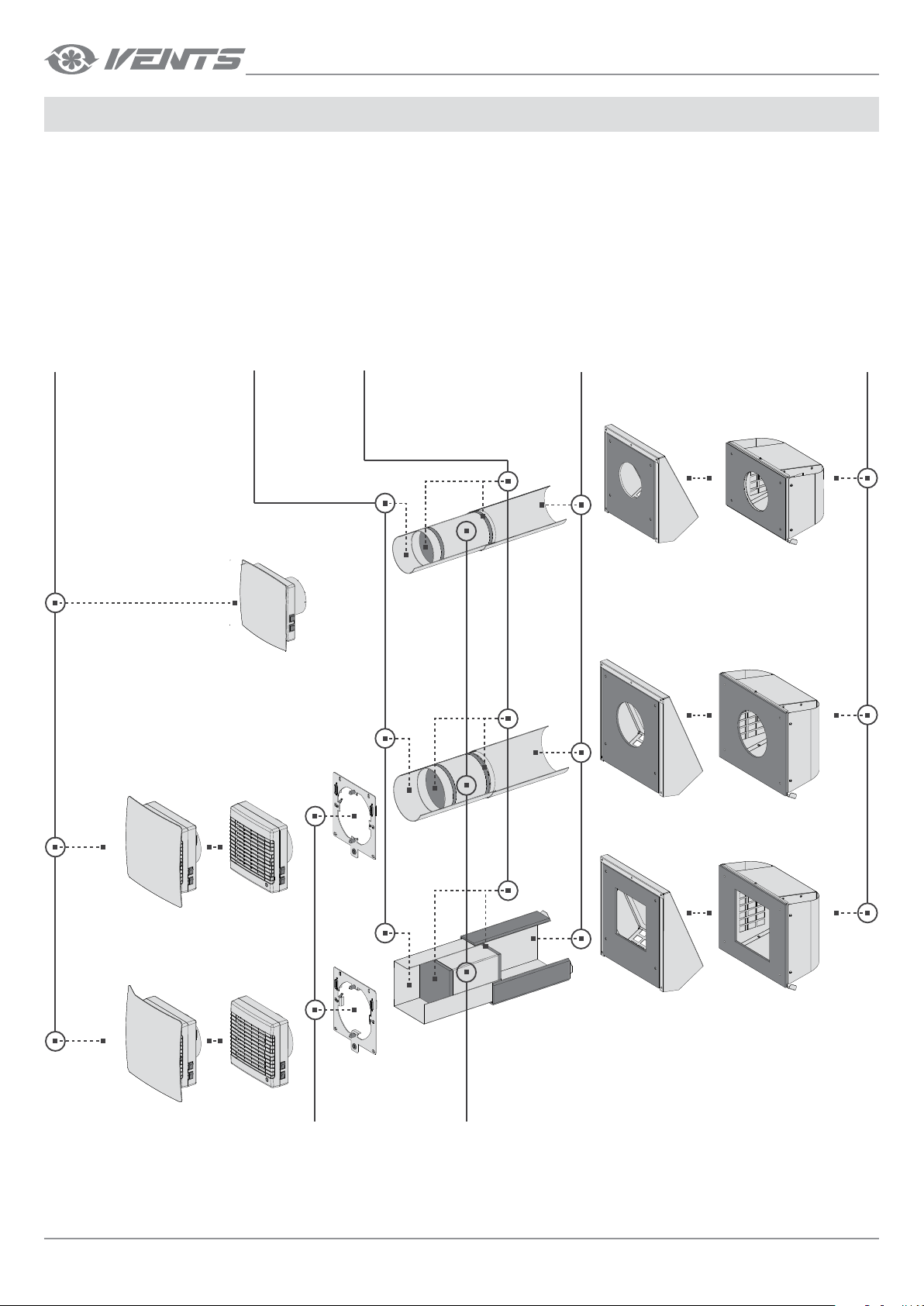
DESIGN AND OPERATING PRINCIPLE
The ventilator consists of a telescopic air duct, a ventilation unit and an outer ventilation hood.
Two filters and a ceramic regenerator are located inside the inner duct of the telescope.
The air filters are designed to purify supply air and prevent ingress of dust and foreign objects into the regenerator and the fan.
The ceramic regenerator utilises extract air heat energy to warm up supply air flow.
The cord laid inside the regenerator is designed to pull the regenerator from the ventilator.
The regenerator is heat insulated with a specially designed insulating material.
The ventilation unit must be installed on inner side of the wall.
The ventilation unit is equipped with automatic shutters that shut the air duct off during the ventilator standby and prevent air back draft.
The ventilation hood must be installed on the outer wall side. It is used for directed air discharge and prevention of ingress of water and other objects
to the ventilator.
VENTILATOR DESIGN
Ventilation unit
Is used to generate air flow by means of the
fan. The ventilation unit is covered with a
ventilation grille on inner wall side to prevent ingress of foreign objects into the fan.
The ventilation unit is equipped with automatic shutters opening when the ventilator
is on and closing when it is off, thus preventing back air flow.
Inner air duct
Inner part of
the telescopic air duct.
Filter
Designed to clean supply air flow
and prevent ingress of dust and
foreign objects to the ventilator.
The filters prevent regenerator
clogging.
Outer air duct
Outer part of
the telescopic air duct.
Outer ventilation hood
Prevents direct ingress of water
and foreign objects to the ventilator.
TwinFresh Comfo RA1-25
TwinFresh Comfo RA1-25-2
TwinFresh Comfo RA-35
TwinFresh Comfo RA-35-2
TwinFresh Comfo RA1-35
TwinFresh Comfo RA1-35-2
TwinFresh Comfo RA-50
TwinFresh Comfo RA-50-2
TwinFresh Comfo RA1-50
TwinFresh Comfo RA1-50-2
TwinFresh Comfo RA-85
TwinFresh Comfo RA-85-2
TwinFresh Comfo RA1-85
TwinFresh Comfo RA1-85-2
TwinFresh Comfo SA-35
TwinFresh Comfo SA-35-2
TwinFresh Comfo SA1-35
TwinFresh Comfo SA1-35-2
Mounting plate
A mounting plate for installation
the ventilation unit on the wall
and connecting the ventilator
to power supply.
8
Ceramic regenerator
Utilises extract air heat energy
to warm up supply air flow.
www.ventilation-system.com
Page 9
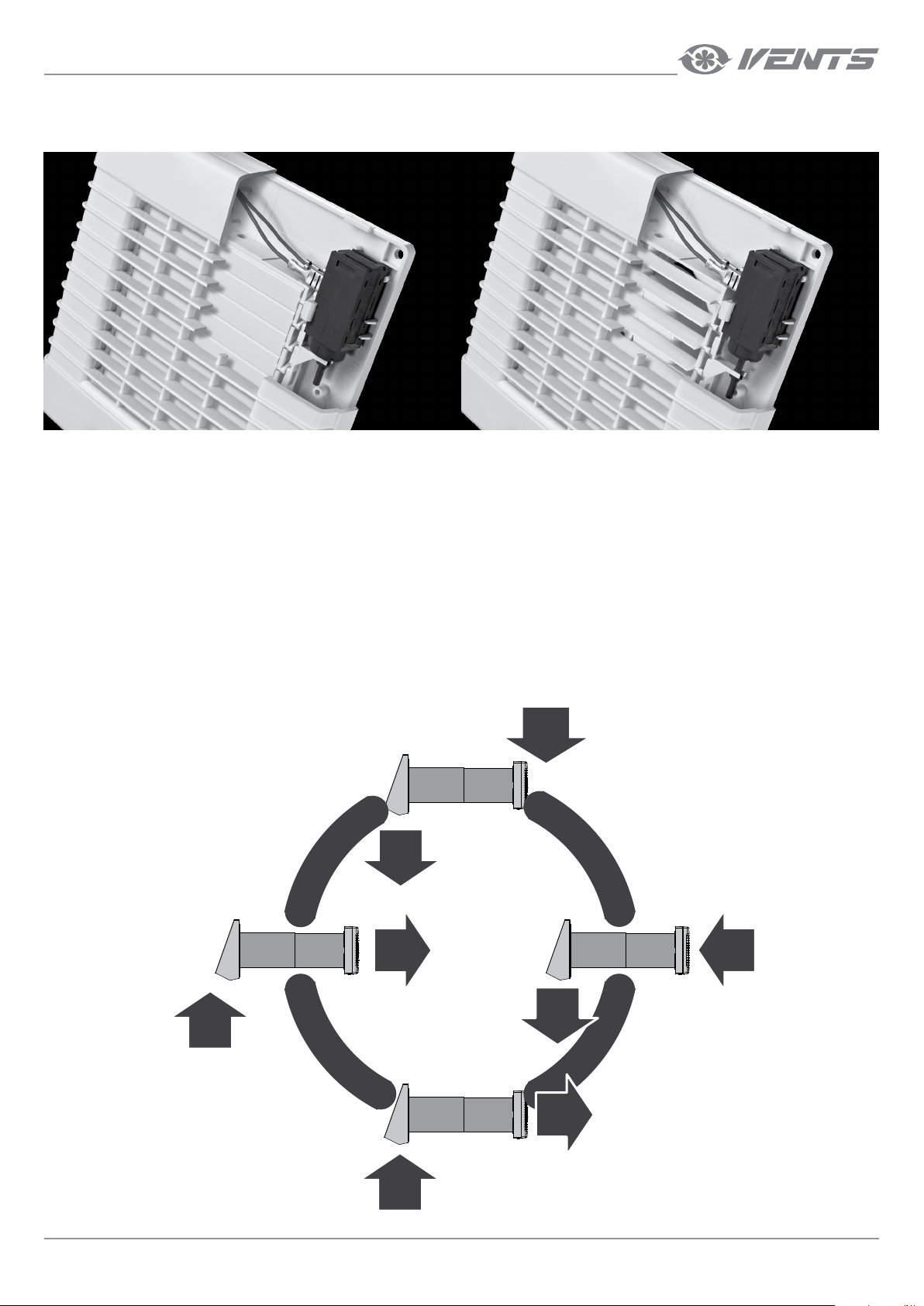
AUTOMATIC SHUTTERS OPERATION
Ventilator is o (the shutters are closed) Ventilator is on (the shutters are opened)
VENTILATOR OPERATION MODES
Ventilator operation modes:
Natural air supply — the automatic shutters are opened, the fan does not run.
Air Supply — the ventilator supplies fresh air to the premise.
Ventilation — the ventilator operates in permanent supply or extract mode at set speed depending on the CN7 jumper position.
Regeneration — the ventilator operates in reversible mode with heat and humidity recovery.
In Regeneration mode the ventilator operates in two cycles, 70 seconds each.
Cycle I.
Warm stale air is extracted from the room. As it flows through the regenerator, it heats and moisturizes the regenerator, transferring up to 90 % heat
energy. In 70 seconds as the ceramic regenerator gets warmed the ventilator is switched to supply mode.
Cycle II.
Fresh intake air from outside flows through the ceramic regenerator, absorbs accumulated moisture and is heated up to the room temperature. In
70 seconds after the regenerator gets cooled down, the ventilator is switched to air extract mode and the cycle is renewed.
+20 °C
A
I
-7 °C
+17 °C
R
E
X
T
7
0
s
R
A
C
T
CYCLE I
+20 °C
-10 °C
CYCLE II
s
Y
L
P
P
U
+17 °C
0
7
S
R
I
A
-7 °C
www.ventilation-system.com
-10 °C
9
Page 10
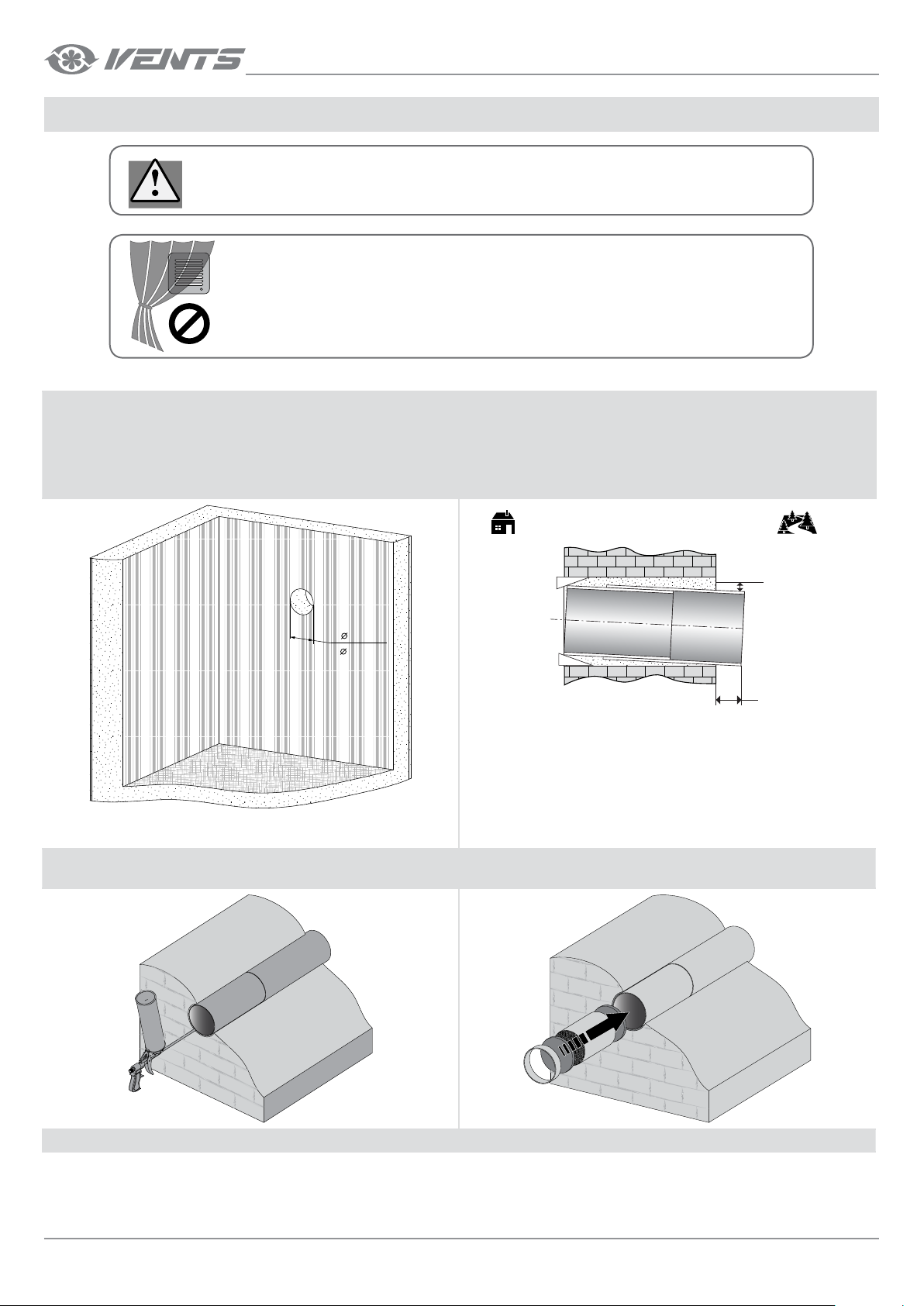
MOUNTING AND SETUP
READ THIS USER’S MANUAL CAREFULLY PRIOR TO THE UNIT INSTALLATION.
DO NOT BLOCK THE AIR DUCT OF THE INSTALLED UNIT WITH DUST ACCUMULATING
MATERIALS, SUCH AS CURTAINS, CLOTH SHUTTERS, ETC. AS IT PREVENTS AIR
CIRCULATION IN THE ROOM.
TWINFRESH COMFO RA125 VENTILATOR MOUNTING
1. Prepare a through hole in the outer wall. The hole size and profile is shown
in the figure below.
TwinFresh Comfo
2. Insert the air duct in the wall. On the outer wall the telescopic air duct
must protrude for the distance that enables installation of the outer
ventilation hood. The distance A is stated in the mounting instruction
for the outer ventilation hood. While mounting the telescopic air duct
be sure to provide the minimum slope 3 mm downwards from outside.
110
( 4 ⁄")
While preparing the hole provide a recess for the cable layout to enable
connection of several ventilators in series.
3. Fill the gaps between the wall and the telescopic air duct with
a mounting foam.
Room Outdoors
min 3 mm
A
4. Install the filter, the ceramic regenerator, another filter and the air flow
rectifier in the consecutive order inside the telescopic air duct.
5. Remove the screw in the bottom part of the ventilator. 6. Remove the front panel of the ventilation unit.
10
www.ventilation-system.com
Page 11
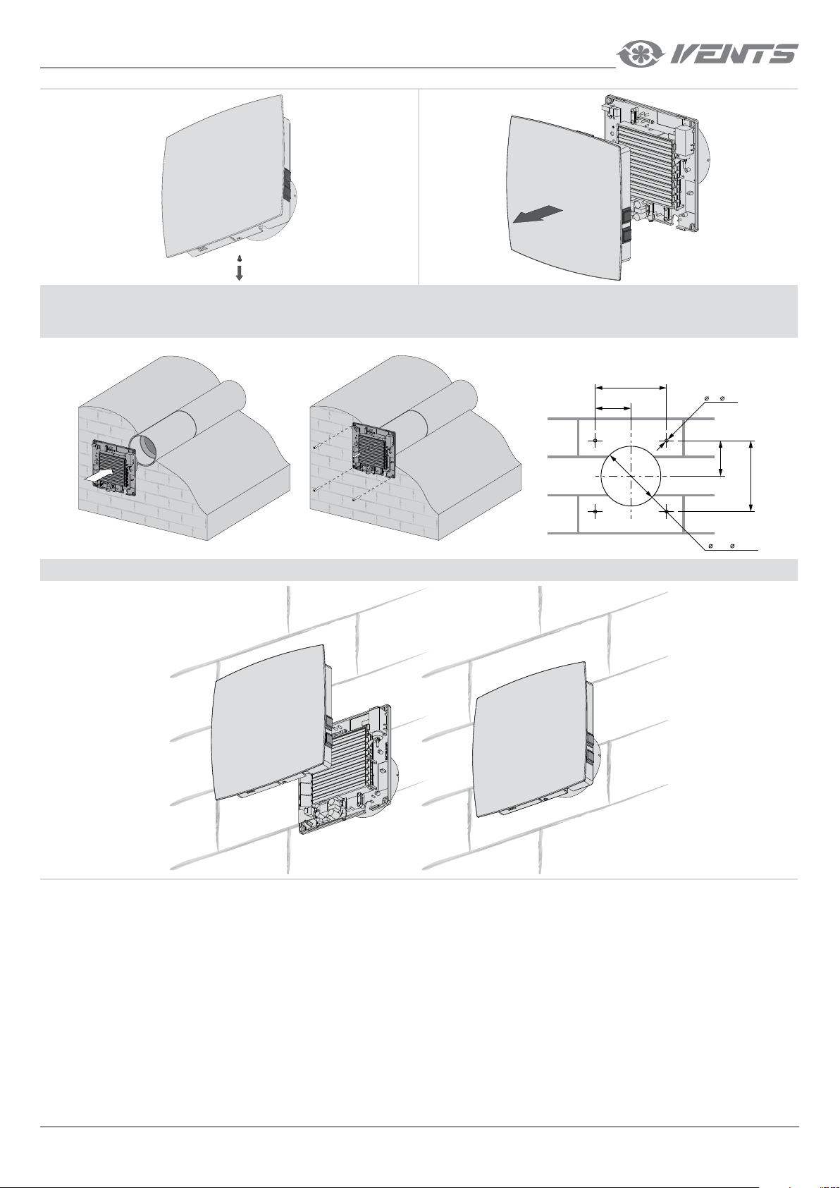
7. Drill four fastening holes and fix the back cover of the ventilation unit on the wall with fours 4x40 screws and 6x60 dowels from the delivery set.
Prior to starting fixation of the back cover of the ventilation unit make arrangements for the power cable layout in accordance to the selected method,
see the Connection to Power Mains section, page 20.
HOLE SPACING FOR THE FAN FASTENERS MM [INCHES]
75
(2 ⁄’’)
8. Connect the contact socket of the switches to the circuit board and install the front panel of the ventilation unit.
150
(5 ⁄’’)
6 ( ¼’’)
4 holes
75
(2 ⁄’’)
110 ( 4 ⁄’’)
150
(5 ⁄’’)
www.ventilation-system.com
11
Page 12
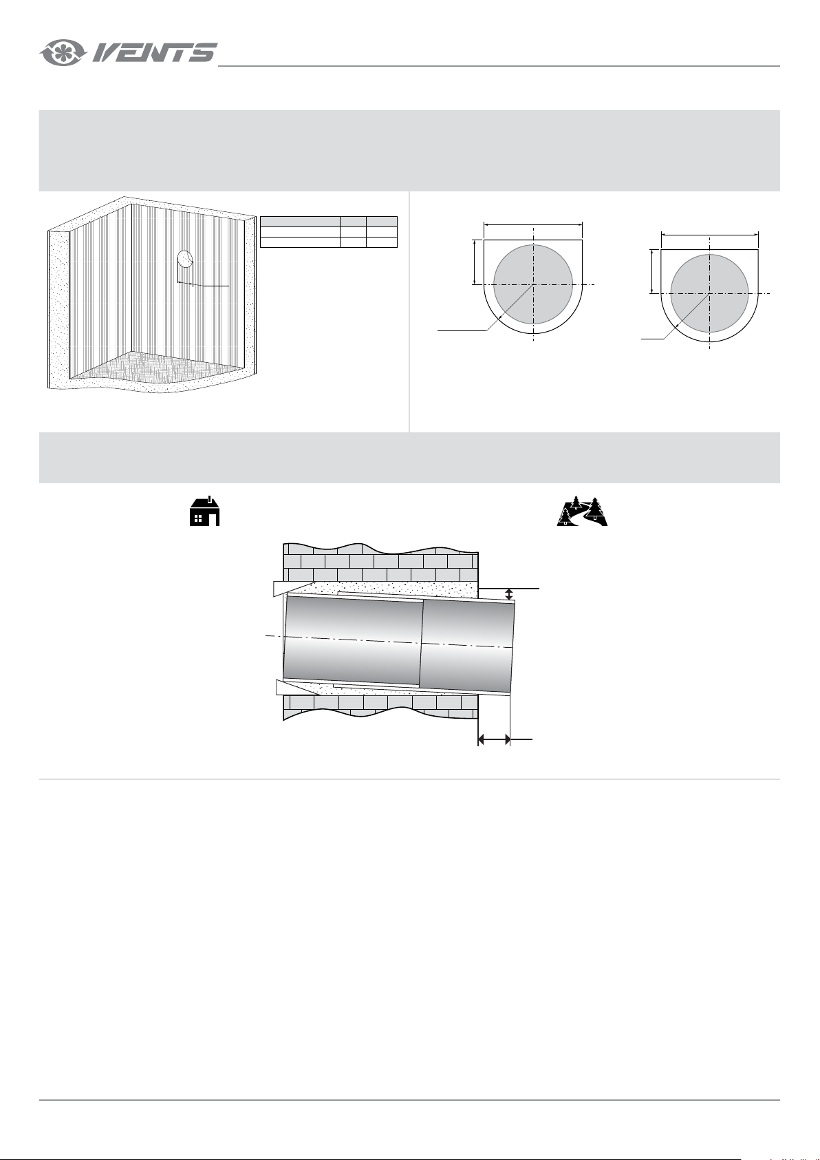
TWINFRESH COMFO RA35, RA50 AND RA85 VENTILATOR MOUNTING
1. Prepare a through hole in the outer wall. The hole size and profile is
shown in the figure below.
Model A, mm
TwinFresh Comfo RA-35 Ø 140 Ø 5 ½”
TwinFresh Comfo RA-50 Ø 160 Ø 6 ⁄”
A [inches]
A
TwinFresh Comfo
2. After preparing a through hole in the wall cut out a 25 mm (1’’) deep
recess for laying of the cables and the contact sockets connected to the
mounting plate.
The recommended recess form is shown in the drawing below.
TwinFresh Comfo RA-35
max 180 (max 7 1/16")
max 80
(max 3 1/8")
TwinFresh Comfo RA-50
TwinFresh Comfo RA-85
max 200 (max 7 ⁄")
max 90
(max 3 ⁄")
R90
(R3 9/16")
R100
(R4")
While mounting several ventilators connected in series provide a cavity
for the cable layout during the recess preparation to enable series
connection of several ventilators.
3. IInsert the air duct in the wall. On the outer wall the telescopic air duct must protrude for the distance that enables installation of the outer ventilation
hood. The distance A is stated in the mounting instruction for the outer ventilation hood. While mounting the telescopic air duct be sure to provide the
minimum slope 3 mm downwards from outside.
Room Outdoors
min 3 mm
12
A
www.ventilation-system.com
Page 13
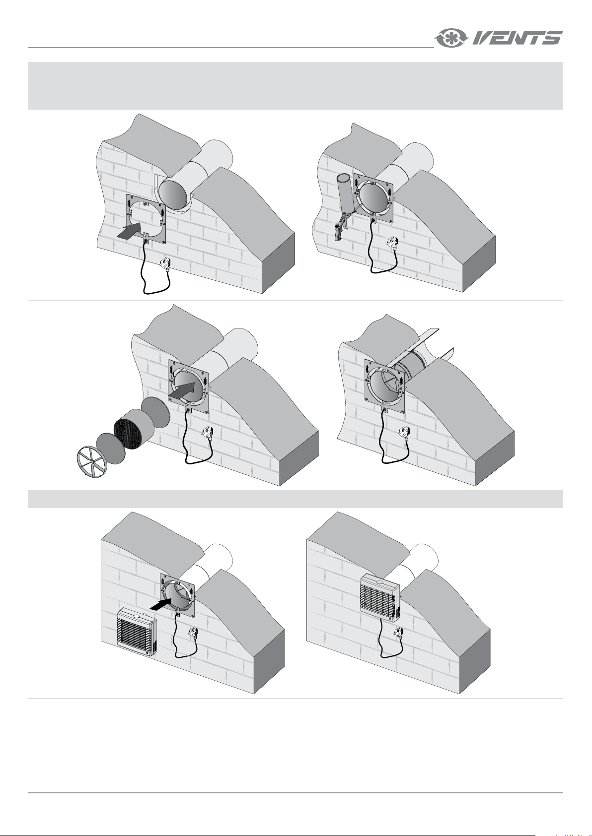
4. Connect the mounting plate following the Wiring Diagram section, page 20.
Drill four fastening holes and fix the mounting plate on the wall with four 4x40 screws and 6x60 dowels from the delivery set.
Align the telescopic air duct with respect to the mounting plate and fill the gaps between the wall and the telescopic air duct with a mounting foam.
The telescopic air duct must not protrude from the mounting plate surface.
5. Install the ventilation unit on the mounting plate. The ventilation unit is fixed with magnets.
www.ventilation-system.com
13
Page 14
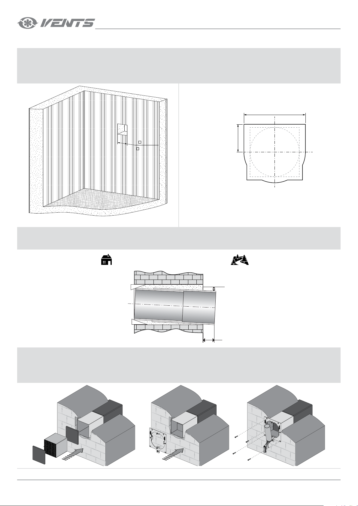
TWINFRESH COMFO SA35 VENTILATOR MOUNTING
1. Prepare a through hole in the outer wall. The hole size and profile is
shown in the figure below.
160
( 6 5/16")
TwinFresh Comfo
2. After preparing a through hole in the wall cut out a 25 mm (1’’) deep
recess for laying of the cables and the contact sockets connected to the
mounting plate.
The recommended recess form is shown in the drawing below.
TwinFresh Comfo SA-35
max 180
(max 7
1
/16")
max 80
(max 3
1
/8")
While mounting several ventilators connected in series provide a cavity
for the cable layout during the recess preparation to enable series
connection of several ventilators.
3. IInsert the air duct in the wall. On the outer wall the telescopic air duct must protrude for the distance that enables installation of the outer ventilation
hood. The distance A is stated in the mounting instruction for the outer ventilation hood. While mounting the telescopic air duct be sure to provide the
minimum slope 3 mm downwards from outside.
Room Outdoors
min 3 mm
A
4. Install the filter, the ceramic regenerator, another filter and the air flow rectifier in the consecutive order inside the telescopic air duct.
Connect the mounting plate following the Wiring Diagram section, page 20.
Drill four fastening holes and fix the mounting plate on the wall with fours 4x40 screws and 6x60 dowels from the delivery set.
Align the telescopic air duct with respect to the mounting plate and fill the gaps between the wall and the telescopic air duct with a mounting foam.
The telescopic air duct must not protrude from the mounting plate surface.
14
www.ventilation-system.com
Page 15
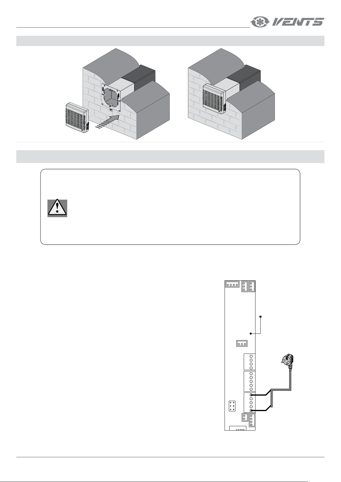
5. Install the ventilation unit on the mounting plate. The ventilation unit is fixed with magnets.
DISCONNECT THE UNIT FROM POWER SUPPLY PRIOR TO ANY OPERATIONS WITH
THE UNIT.
INSTALLATION SHALL ONLY BE PERFORMED BY A PROFESSIONAL ELECTRICIAN
QUALIFIED FOR UNASSISTED OPERATIONS WITH ELECTRICAL INSTALLATIONS
UP TO 1000 V AFTER CAREFUL STUDY OF THE PRESENT USER’S MANUAL.
THE RATED ELECTRICAL PARAMETERS OF THE UNIT ARE GIVEN ON THE
MANUFACTURER’S LABEL. ANY INTERNAL CONNECTION MODIFICATIONS ARE NOT
ALLOWED AND RESULT IN WARRANTY LOSS.
CONNECTION TO POWER MAINS
The ventilator is rated for connection to a single-phase AC 1~100-240 V/50 (60) Hz.
For this purpose the power cable with a plug is connected by the Manufacturer.
Connect the ventilator to power mains through the external automatic circuit breaker with a magnetic trip integrated into the fixed wiring system.
VENTILATOR WIRING DIAGRAM
TWINFRESH COMFO RA125
TWINFRESH COMFO RA1252
The jumper between the contacts 1 and 2 or 2 and 3 of the CN7 socket connector determines
air flow direction in Ventilation mode.
• If the jumper connects the contacts 1 and 2, air is extracted from the room in the Ventilation
XS4
A1
XS2 XS1
Ventilator
controller
mode (factory setting).
• If the jumper connects the contacts 2 and 3, air is supplied in the Ventilation mode.
XS3
1~100-240 V
50 (60) Hz
TB3
L
1
2
3
TB1
L
G
D
+
N
TB2
L
G
4
D
5
+
6
N
1
2
3
CN7
www.ventilation-system.com
15
Page 16
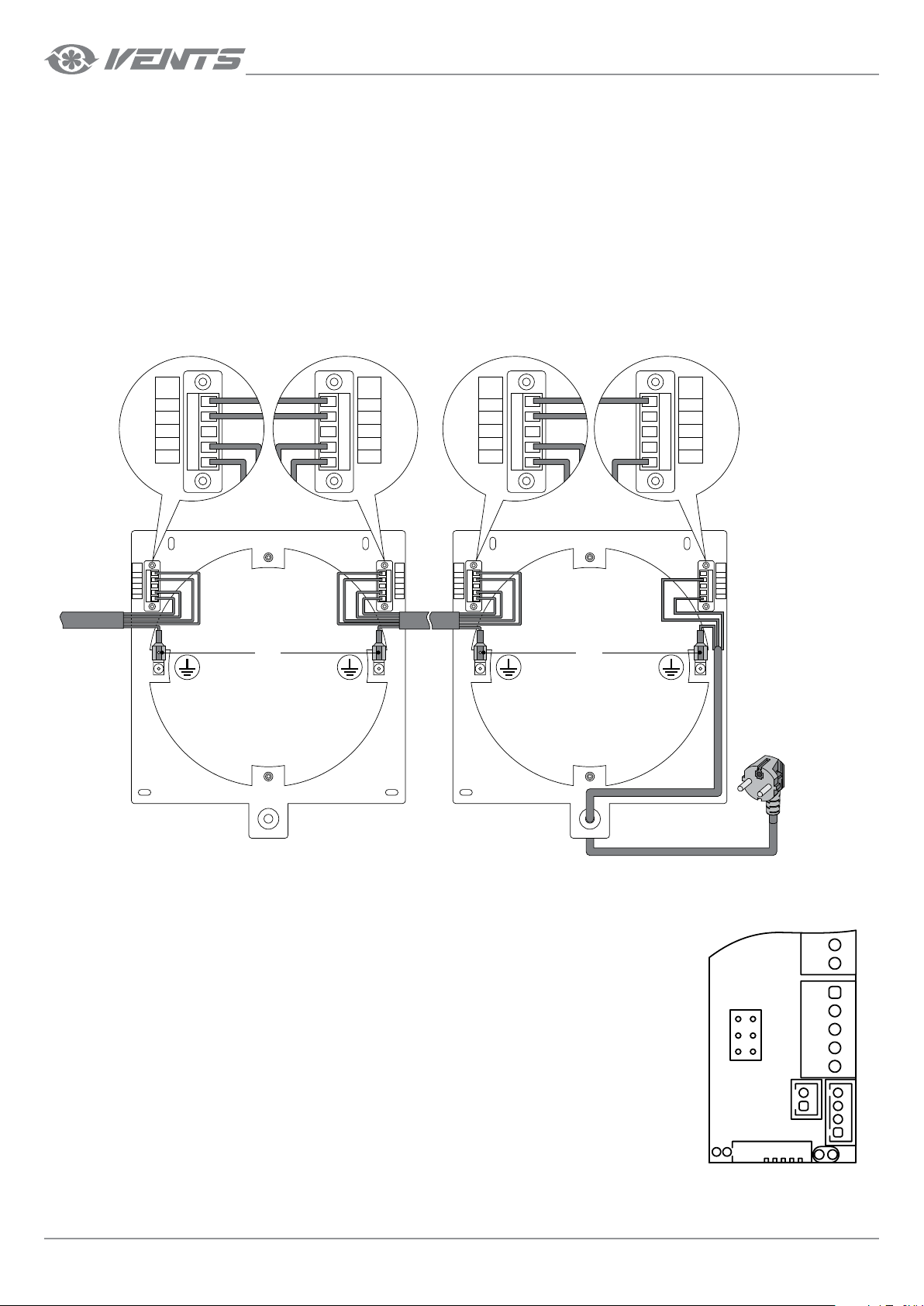
TwinFresh Comfo
CONNECTION OF SEVERAL VENTILATORS IN SERIES
TWINFRESH COMFO SA35
TWINFRESH COMFO SA352
TWINFRESH COMFO SA135
TWINFRESH COMFO SA1352
TWINFRESH COMFO RA35
TWINFRESH COMFO RA352
TWINFRESH COMFO RA135
TWINFRESH COMFO RA1352
Connection of the ventilators in series enables controlling all the connected ventilators by the first ventilator and the common remote control. To
connect the ventilators in series connect the Output contact socket of the first ventilator mounting plate with the Input contact socket of the second
ventilator mounting plate. Connect the second ventilator with the third ventilator in the same way, etc. Maximum 10 ventilators may be connected
in series. For easy electric installation use a five-wire cable (not included into the delivery set) with the cable cross section not below 0.5 mm2. The
cable must be rated for operation in an alternating current power supply with the country-specific mains voltage.
Disconnect the power cable while connecting the second, third, etc. ventilator in series.
CONNECTION OF SEVERAL VENTILATORS IN SERIES BACKSIDE VIEW
TWINFRESH COMFO RA50
TWINFRESH COMFO RA502
TWINFRESH COMFO RA150
TWINFRESH COMFO RA1502
TWINFRESH COMFO RA85
TWINFRESH COMFO RA852
TWINFRESH COMFO RA185
TWINFRESH COMFO RA1852
TO THE NEXT
VENTILATOR
Output
L
G
D
N
Input
L
G
D
N
Output
L
G
D
N
Input
L
G
D
N
Ventilator no.2 Ventilator no.1
Output
L
G
D
N
ground
terminal
ground
terminal
Input
L
G
D
N
Output
L
G
D
N
ground
terminal
ground
terminal
Input
L
G
D
N
1~100-240
V/50 (60) Hz
The first ventilator controls all the connected ventilators.
The jumper between the contacts 1 and 2 or 2 and 3 of the CN7 socket connector determines a flow direction in
Ventilation mode.
• If the jumper connects the contacts 1 and 2, air is extracted from the room in the Ventilation mode (factory
setting).
• If the jumper connects the contacts 2 and 3, air is supplied in the Ventilation mode.
The jumper position at each ventilator connected in series determines a rotation direction in Ventilation mode
and an operating phase in Regeneration mode.
I.e. if the jumper at the first ventilator connects the contacts 2 and 3 and the jumper at the second ventilator
connects the contacts 1 and 2, the ventilators operate in opposite directions in Regeneration mode.
16
Ventilator
controller
+
+
N
N
TB2
L
CN7
1
4
2
5
3
6
www.ventilation-system.com
L
G
G
D
D
+
+
N
N
Page 17
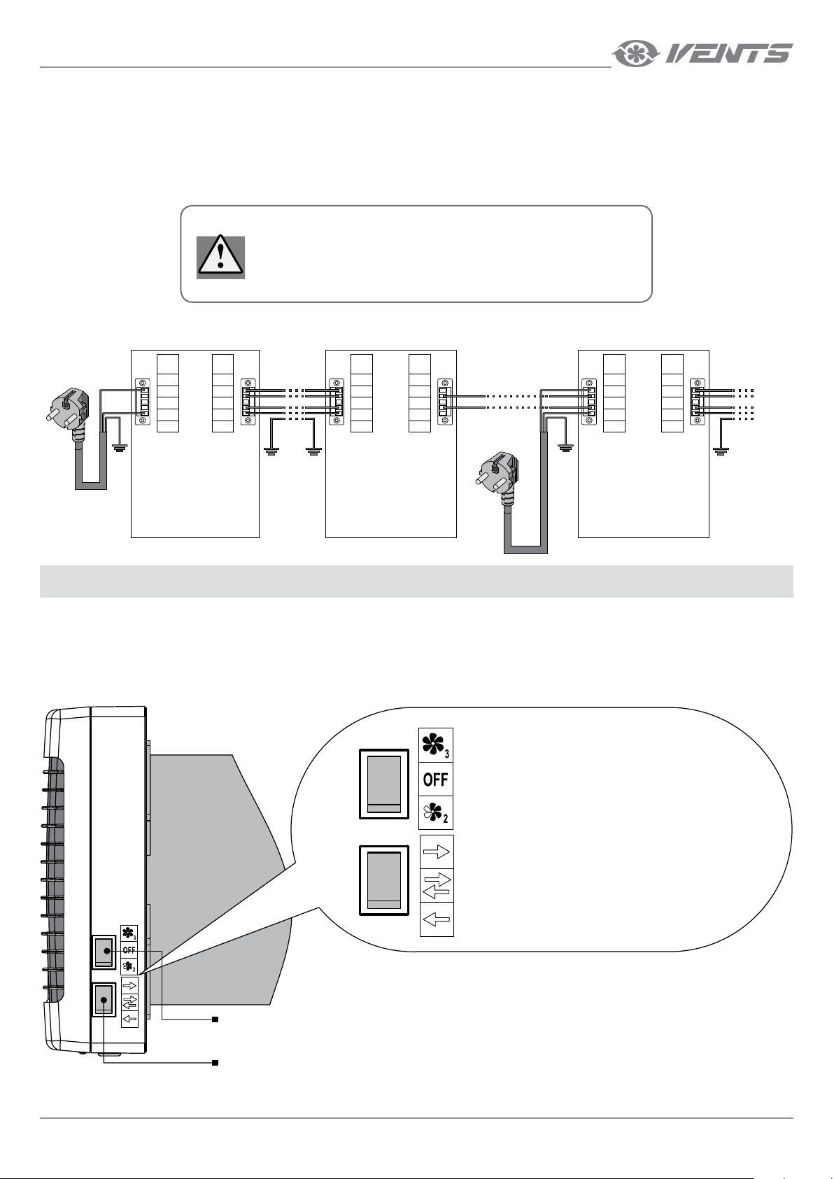
CONNECTION OF MORE THAN 10 VENTILATORS IN SERIES
In case of connection of more than 10 ventilators the ventilator 11 is energized not through the previous ventilator but from power mains (L and N
terminals).
The control signals G and D from the 10th ventilator are transferred through the cable 2 x 0.5 mm
2
.
Connect the ventilators no. 12…20 to the ventilator no. 11 in the same way as the ventilators no. 1…10.
All the connected ventilators are controlled with the ventilator no. 1.
ALL THE CONNECTED IN SERIES VENTILATORS MUST BE
GROUNDED!
Ventilator no.1 Ventilator no.10 Ventilator no.11
1~100-240 V
50 (60) Hz
Input
L
G
D
N
Output
L
G
D
N
Input
L
G
D
N
Output
L
G
D
N
1~100-240 V
50 (60) Hz
Input
L
G
D
N
Output
L
G
D
N
TO THE NEXT
VENTILATOR
VENTILATOR CONTROL
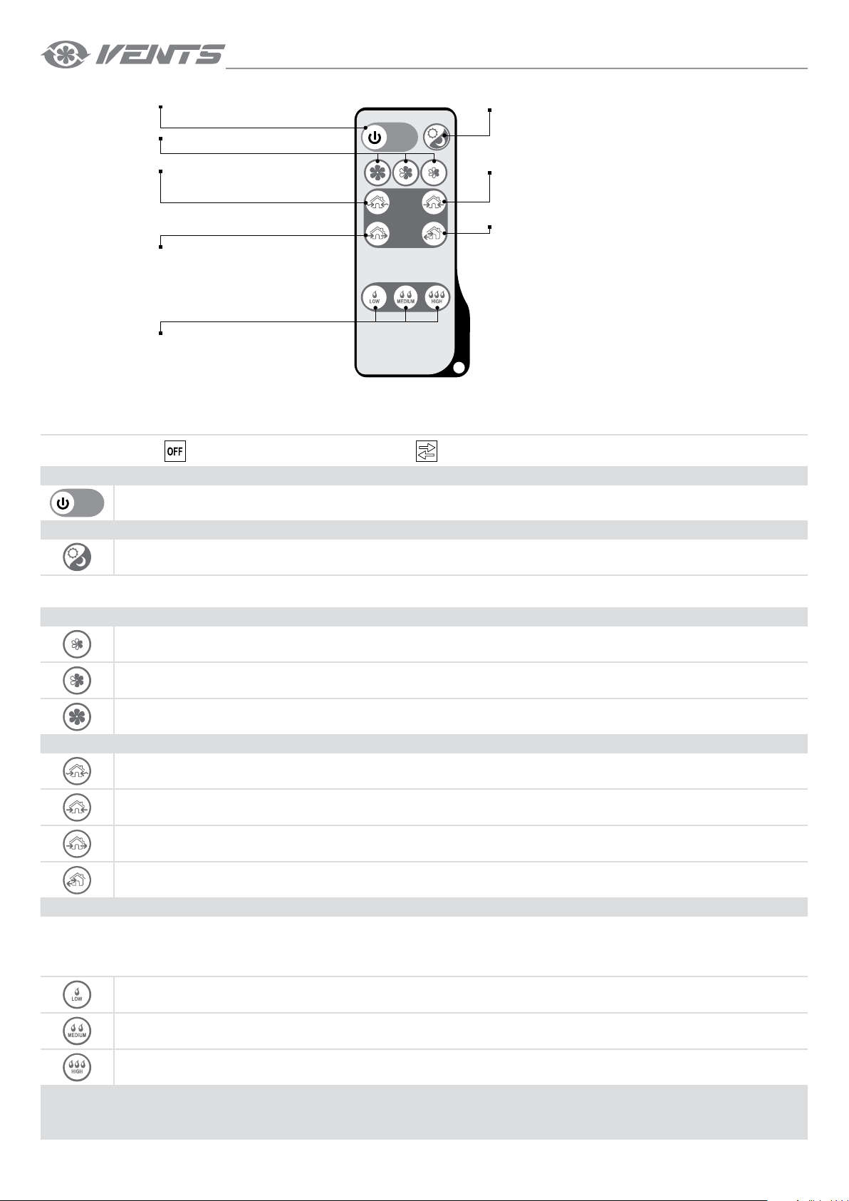
The ventilator is operated with a remote control or the buttons on the ventilator casing, see the figure below.
The operation buttons on the ventilator casing have limited functionality: only the second and the third speed can be activated. Three of the four
modes of ventilation may be set.
The remote control has wider control capabilities.
CONTROL BUTTONS ON THE VENTILATOR CASING
Third speed
The ventilator operates with maximum air flow.
The fan is o
The ventilator does not operate. The shutters are closed.
Second speed
The ventilator operates with 50 % air flow.
Ventilation mode
The ventilator operates either in extract or supply mode with no reference
to the CN7 jumper position.
Regeneration mode
In this mode the ventilator switches between supply and extract every 70 seconds.
Heat recovery is performed in this mode.
Supply mode
All the connected in series ventilators operate in supply mode with no
reference to the CN7 jumper position.
The buttons on the casing can be arranged in a different
sequence depending on the ventilator model. Consider the
information on the stickers near the control buttons while using
Speed switch
the buttons.
www.ventilation-system.com
Ventilation mode switch
17
Page 18
TwinFresh Comfo
Turning ventilator
ON/OFF
Speed selection
Passive air supply
The shutters are open,
the fan does not run.
Ventilation
The ventilator operates either in extract or
supply mode with no reference to the CN7
jumper position.
Humidity set point setting
1
— operation of all the ventilators connected in series is determined by the CN7 jumper position.
1
REMOTE CONTROL
Night mode
The ventilator switches to the first speed
in the darkness.
Air supply
The unit operates in supply mode with
no reference to the CN7 jumper position.
Heat recovery
The ventilator switches between supply
and extract every 70 seconds.
Heat recovery is performed in this mode.
REMOTE CONTROL
Set the speed switch to
position and the ventilation mode switch to position to enable remote control of the ventilation unit.
1. Turning the ventilator ON/OFF
ON/OFF
2. Night mode
ON/OFF
If the Night mode is activated, the ventilator switches to the first speed in the dark time of the day when the light is turned off.
Activation of the night mode is confirmed by a long sound signal. Exiting the night mode is confirmed by a short sound signal.
3. Speed changeover
First speed
Second speed
Third speed
4. Operation mode
Natural air supply mode. The room is ventilated in the natural way, the fan is off.
Air supply mode. Air is supplied to the room at a set speed. All connected in series ventilators operate in air supply mode with no
reference to the CN7 jumper position.
Ventilation mode. Air is extracted (factory setting) or supplied at a selected speed. All the ventilators connected in series operate
depending on the CN7 jumper position.
Regeneration mode. The ventilator operates 70 seconds in supply mode and then 70 seconds in extract mode. Heat recovery is
performed in this mode.
5. Humidity Control mode.
The humidity control may be activated in the Regeneration mode only by pressing one of the humidity control buttons. In the Humidity Control
mode the ventilator measures the humidity of the extract air. If the humidity exceeds the selected set point the ventilator switches to a higher speed.
After reaching the required level of the ventilator switches to a lower speed. Press one of the speed selection buttons to deactivate the Humidity
Control mode.
18
Setting humidity set point — 45 %.
Setting humidity set point — 55 %.
Setting humidity set point — 65 %.
HUMIDITY CONTROL FUNCTION MAY BE ACTIVATED WITH THE REMOTE CONTROL ONLY!
www.ventilation-system.com
Page 19
TECHNICAL MAINTENANCE
DISCONNECT THE VENTILATOR FROM POWER SUPPLY PRIOR
TO ANY MAINTENANCE OPERATIONS.
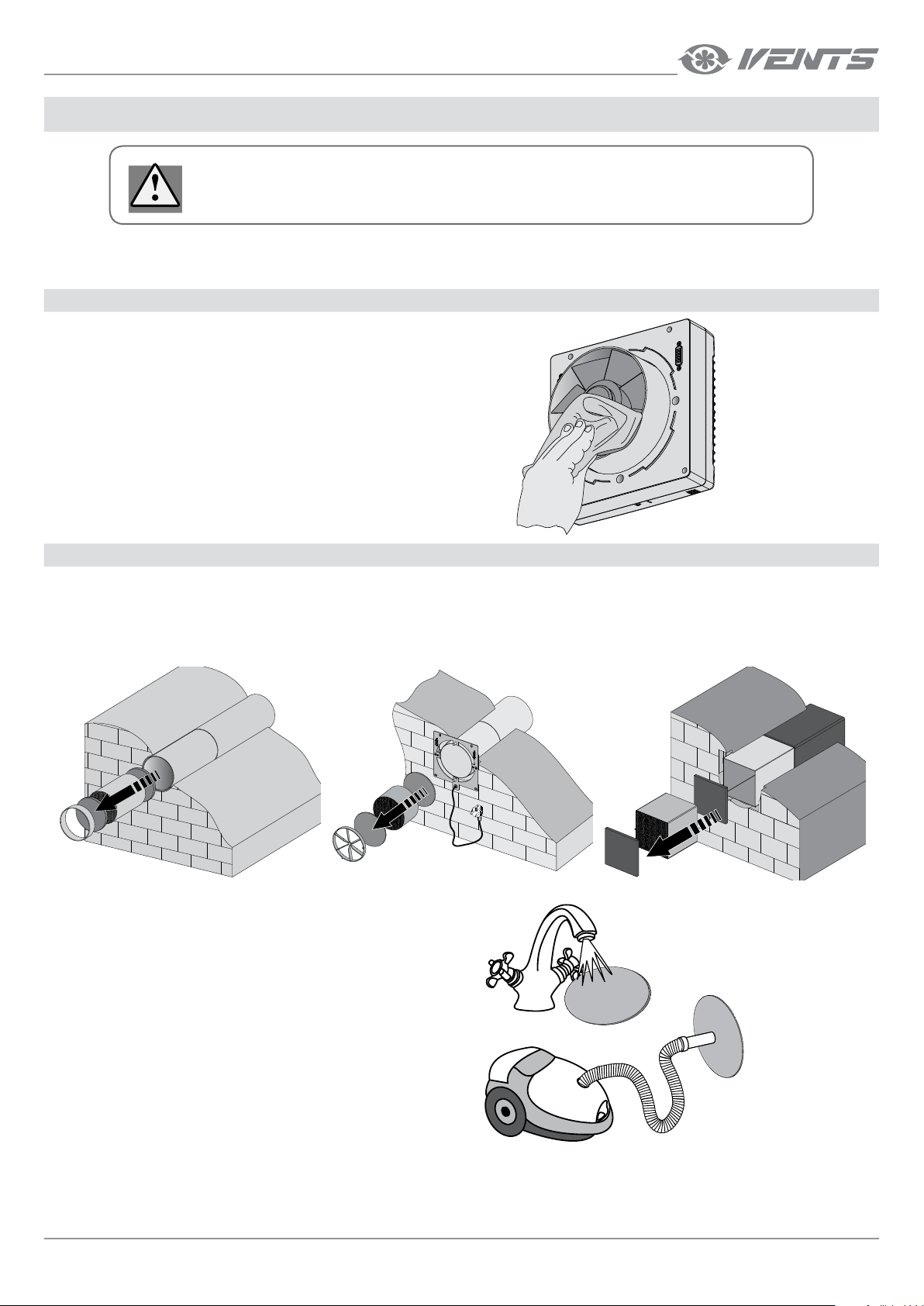
Maintenance of the ventilator means regular cleaning of the ventilator surfaces of dust and cleaning or replacement of the filters.
MAINTENANCE
1. Fan inspection (once per year).
Take off the ventilation unit and clean the fan blades.
To remove dust use a soft brush, cloth or a vacuum
cleaner.
Do not use water, abrasive detergents, solvents,
sharp objects for cleaning.
Clean the impeller blades once a year.
2. Regenerator and lter maintenance (3-4 times per year).
1. Remove the air flow rectifier.
2. Remove the filter upstream of the regenerator.
3. Pull the specially designed cord to remove the regenerator from the air duct.
4. Be careful while pulling the regenerator to avoid its damage.
5. Remove the filter downstream of the regenerator.
Clean the filters as often as required, but at least
3 times a year.
• After the expiry of time to filter cleaning (90 days)
the ventilator generates periodically a sound
signal as a reminder of the need to replace or
clean the filters.
• Wash the filters and let them get dry. Install dry
filters in the air duct.
• Vacuum cleaning is allowed.
• The filter rated service life is 3 years.
• For new filters contact the Seller.
www.ventilation-system.com
19
Page 20
TwinFresh Comfo
Even regular technical maintenance may not
completely prevent dirt accumulation on the
regenerator assemblies.
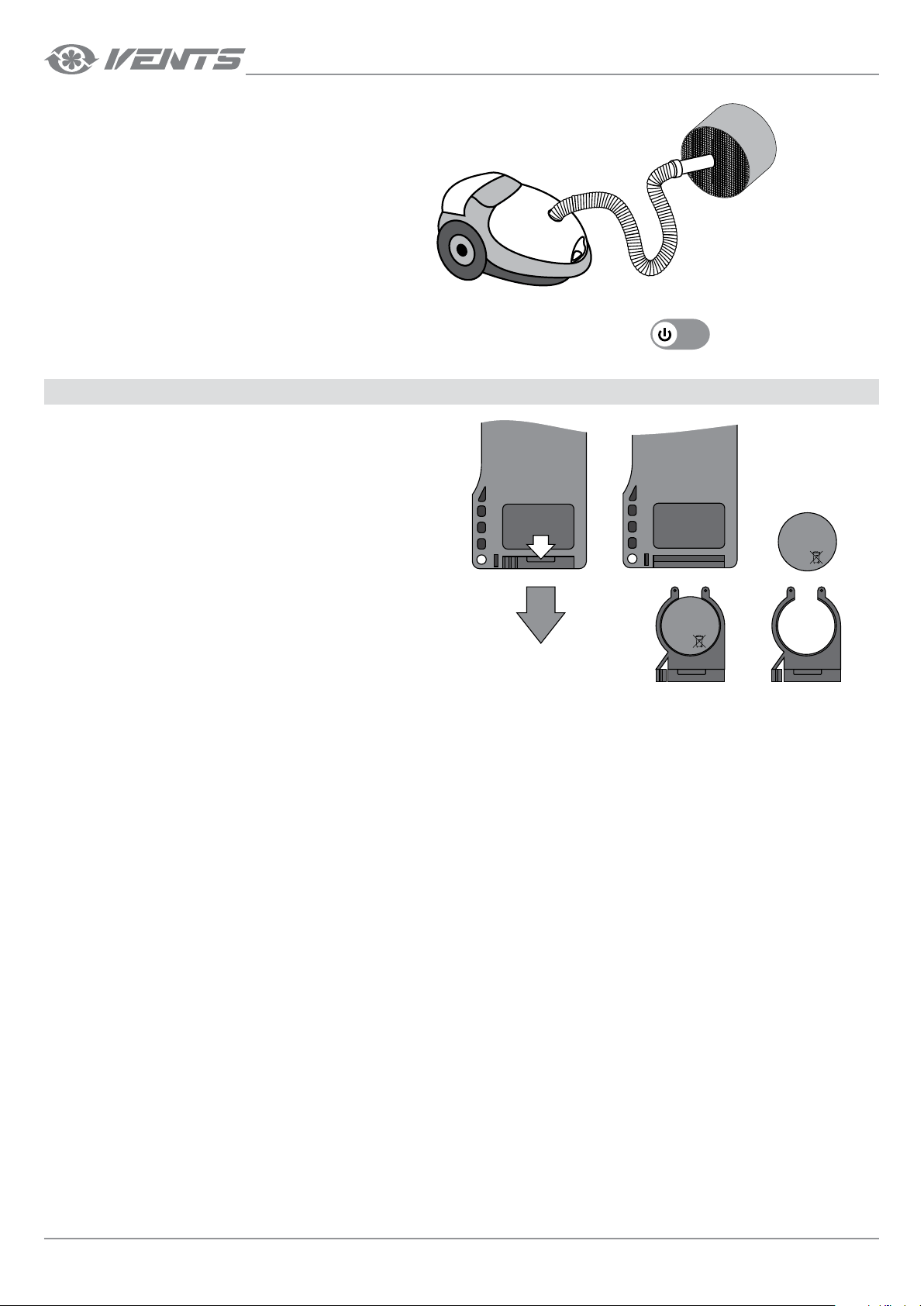
• Subject the regenerator to regular cleaning to
ensure high heat recovery efficiency.
• Vacuum clean the regenerator not less than once
a year.
To reset the hour meter install the filters and the regenerator into the ventilator and then press and hold the button for 10 sec. until you
hear a long sound signal.
3. Replacement of the remote control battery (if necessary).
Replace the battery of the remote control after prolonged use.
No response of the unit for pressing the remote control buttons
indicates the need to replace the battery.
Battery type: CR2025.
To replace the battery of the remote control remove the battery holder
with a battery. Replace the battery and install the holder with a new
battery back to the remote control.
+
CR2025
3V
+
CR2025
3V
20
www.ventilation-system.com
Page 21

TROUBLESHOOTING
POSSIBLE REASONS AND TROUBLESHOOTING
Problem Possible reasons Troubleshooting
When switching on the
ventilator the fan does not
start.
Circuit breaker tripping during
the ventilator start-up.
Low air flow.
The ventilator generates
sound signals.
Noise, vibration.
No power supply.
The motor is jammed, the impeller blades are clogged.
Overcurrent as a result of short circuit in the electric
circuit.
Low set fan speed. Set higher speed.
The filters, the fan or the regenerator are clogged.
The filter timer is actuated. Refer to the Technical maintenance section, clause 2.
The impeller is clogged. Clean the impeller.
Loose screw connection of the ventilator casing or the
ventilation hood.
Make sure the power supply line is connected correctly,
otherwise troubleshoot the connection error.
Turn the ventilator off. Troubleshoot the motor jam and
the impeller clogging. Clean the blades. Restart the
ventilator.
Turn the ventilator off.
Contact the Seller for further information.
Clean or replace the filters. Clean the fan and the
regenerator.
Tighten the screws of the ventilator or the outer
ventilation hood.
STORAGE AND TRANSPORTATION REGULATIONS
Store the unit in the manufacturer’s original packing box in a dry closed ventilated premise with temperature range from +5 °C (+ 41 ˚F) to + 40 °C
(104 ˚F).
Storage environment must not contain aggressive vapours and chemical mixtures provoking corrosion, insulation and sealing deformation.
Use suitable hoist machinery for handling and storage operations to prevent possible damage to the unit.
Follow the handling requirements applicable for the particular type of cargo.
The unit can be carried in the original packing by any mode of transport provided proper protection against precipitation and mechanical damage.
Avoid sharp blows, scratches or rough handling during loading and unloading.
www.ventilation-system.com
21
Page 22
TwinFresh Comfo
MANUFACTURER’S WARRANTY
The manufacturer hereby warrants normal operation of the unit for 24 months after the retail sale date provided the user’s observance of the
transportation, storage, mounting and operation regulations.
Should any malfunctions occur in the course of the unit operation through the Manufacturer’s fault during the guaranteed period of operation the user
is entitled to elimination of faults by the manufacturer by means of warranty repair at the factory free of charge.
The warranty repair shall include work specific to elimination of faults in the unit operation to ensure its intended use by the user within the guaranteed
period of operation.
The faults are eliminated by means of replacement or repair of the unit components or a specific part of such unit component.
The warranty repair does not include:
• routine technical maintenance
• unit installation/dismantling
• unit setup
To benefit from warranty repair the user must provide the unit, the user’s manual with the purchase date stamp and the payment document certifying
the purchase.
The unit model must comply with the one stated in the user’s manual.
Contact the Seller for warranty service.
The manufacturer’s warranty does not apply to the following cases:
• User’s failure to submit the unit with the entire delivery package as stated in the user’s manual including submission with missing component parts
previously dismounted by the user.
• Mismatch of the unit model and the brand name with the information stated on the unit packing and in the user’s manual.
• User’s failure to ensure timely technical maintenance of the unit.
• External damage to the unit casing (excluding external modifications as required for installation) and internal components caused by the user.
• Redesign or engineering changes to the unit.
• Replacement and use of any assemblies, parts and components not approved by the manufacturer.
• Unit misuse.
• User’s violation of the unit installation regulations.
• User’s violation of the unit control regulations.
• Unit connection to the power mains with a voltage different from the one stated in the user’s manual.
• Unit breakdown due to voltage surges in the power mains.
• Discretionary repair of the unit by the user.
• Unit repair by any persons without the manufacturer’s authorization.
• Expiration of the unit warranty period.
• User’s violation of the unit transportation regulations.
• User’s violation of the unit storage regulations.
• Wrongful actions against the unit committed by third parties.
• Unit breakdown due to circumstances of insuperable force (fire, flood, earthquake, war, hostilities of any kind, blockades).
• Missing seals if provided by the user’s manual.
• Failure to submit the user’s manual with the unit purchase date stamp.
• Missing payment document certifying the unit purchase.
22
FOLLOWING THE REGULATIONS STIPULATED HEREIN WILL ENSURE
A LONG AND TROUBLEFREE OPERATION OF THE UNIT.
USERS’ WARRANTY CLAIMS SHALL BE SUBJECT TO REVIEW ONLY UPON PRESENTATION OF THE
UNIT, THE PAYMENT DOCUMENT AND THE USER’S MANUAL WITH THE PURCHASE DATE STAMP.
www.ventilation-system.com
Page 23
ACCEPTANCE CERTIFICATE
Unit Type Single-room reversible energy recovery ventilator
Model TwinFresh Comfo _________
Serial Number
Manufacture Date
Is compliant with the technical specifications and is recognized as serviceable.We hereby declare that the product complies with the essential
protection requirements of Electromagnetic Council Directive 2004/108/EC, 89/336/EEC and Low Voltage Directive 2006/95/EC, 73/23/EEC and
CE-marking Directive 93/68/EEC on the approximation of the laws of the Member States relating to electromagnetic compatibility. This certificate is
issued following test carried out on samples of the product referred to above.
Quality
Inspector’s Stamp
SELLER INFORMATION
Seller
Address
Phone Number
E-mail
Purchase Date
This is to certify acceptance of the complete ventilator delivery with the user’s manual. The warranty terms are
acknowledged and accepted.
Customer’s Signature
INSTALLATION CERTIFICATE
The single-room reversible energy regeneration ventilator TwinFresh Comfo _________ has been connected to
power mains pursuant to the requirements stated in the present user’s manual.
Company Name
Address
Phone Number
Installation Technician's
Full Name
Installation Date: Signature:
The ventilator has been installed in accordance with the provisions of all the applicable local and national
construction, electrical and technical codes and standards. The ventilator operates normally as intended by the
manufacturer.
Signature:
Unit Type Single-room reversible energy recovery ventilator
Model TwinFresh Comfo _________
Serial Number
Manufacture Date
Purchase Date
Warranty Period
Seller
Seller’s Stamp
Installation Company Stamp
WARRANTY CARD
www.ventilation-system.com
Seller’s Stamp
23
Page 24

V91EN-03
 Loading...