

Vents CBF 110 DC T, CBF 110 DC LIGHT TP, CBF 110 DC TP, CBF 110 DC LIGHT TH, CBF 150 DC T User Manual
...Page 1
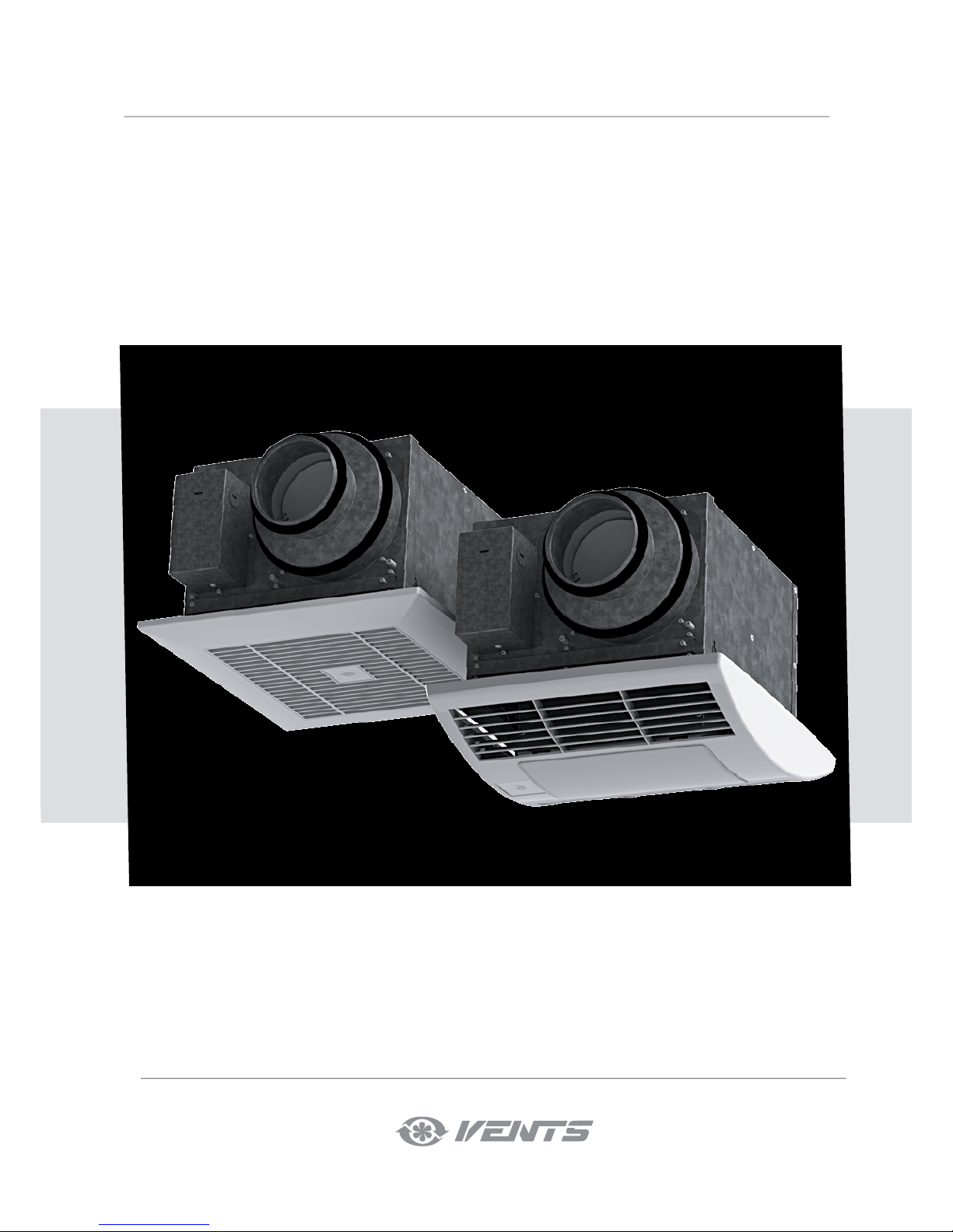
CBF 110 DC T/TH/TP
CBF 110 DC LIGHT T/TH/TP
CBF 150 DC T/TH/TP
CBF 150 DC LIGHT T/TH/TP
Centrifugal ceiling fan
USER’S MANUAL
Page 2
2
CBF DC
www.ventilation-system.com
CONTENTS
This user’s manual is the primary operating document intended for technical, maintenance and operations staff.
The user’s manual contains information regarding the field of application, delivery package, operating principle, and design of the
centrifugal fan CBF DC fan and all its modifications.
Technical and maintenance staff must have proper theoretical knowledge and practical training specific to ventilation systems as well as
the necessary skills to carry out the work in accordance with labour safety and construction regulations and standards applicable in the
respective territory.
The information provided in the present document is true as at the document preparation.
Due to the continuous product development the company reserves the right to update the technical specifications, design or delivery
package of its products.
No part of the present publication may be reproduced, uploaded or saved in reference-providing information systems or translated into
other languages in any form whatsoever without the company’s prior written consent.
SAFETY REQUIREMENTS
• Please read the user's manual carefully prior to installing and operating the unit.
• All user's manual requirements as well as the provisions of all the applicable local and national construction, electrical, and
technical norms and standards must be observed when installing and operating the unit.
• The warnings contained in the user’s manual must be considered most seriously since they contain vital personal safety information.
• Failure to follow the rules and safety precautions noted in this user’s manual may result in an injury or unit damage.
• After a careful reading of the manual, keep it for the entire service life of the unit.
• While transferring the unit control, the user's manual must be turned over to the receiving operator.
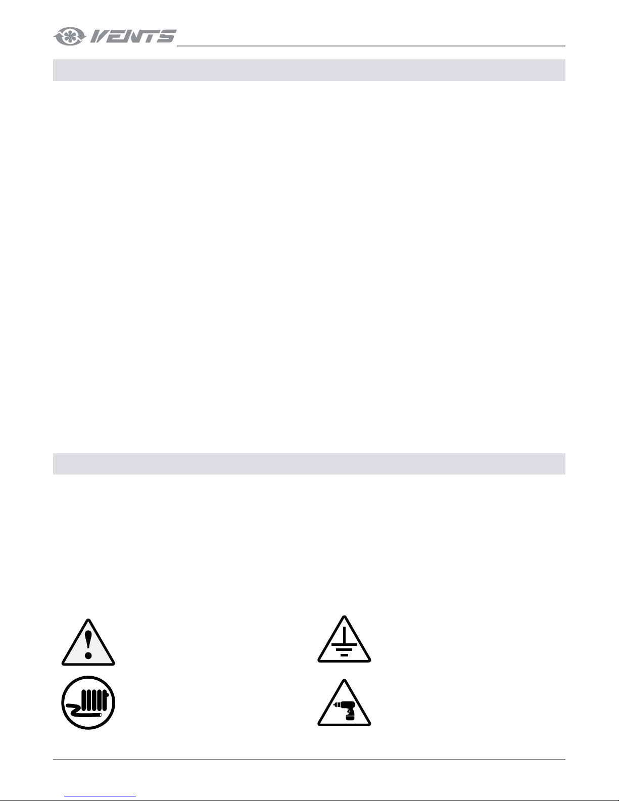
UNIT INSTALLATION AND OPERATION SAFETY PRECAUTIONS
• Disconnect the unit from power mains
prior to any installation operations.
• The unit must be grounded!
• Do not lay the power cable of the unit in
close proximity to heating equipment.
• While installing the unit, follow the
safety regulations specific to the use of
electric tools.
Contents .............................................................................................................................................................................................. 2
Safety requirements .....................................................................................................................................................................2
Purpose ................................................................................................................................................................................................ 4
Delivery Set ....................................................................................................................................................................................... 4
Designation key ............................................................................................................................................................................ 4
Technical data ..................................................................................................................................................................................5
Design and operating principle ........................................................................................................................................... 6
Mounting and set-up ................................................................................................................................................................ 7
Connection to power mains ................................................................................................................................................. 10
Control ................................................................................................................................................................................................. 11
Maintenance .................................................................................................................................................................................... 12
Storage and transportation regulations ........................................................................................................................ 14
Manufacturer’s warranty ........................................................................................................................................................... 15
Acceptance certificate .............................................................................................................................................................. 16
Seller information ......................................................................................................................................................................... 16
Installation certificate .................................................................................................................................................................. 16
Warranty card ...................................................................................................................................................................................16
Page 3
3
www.ventilation-system.com
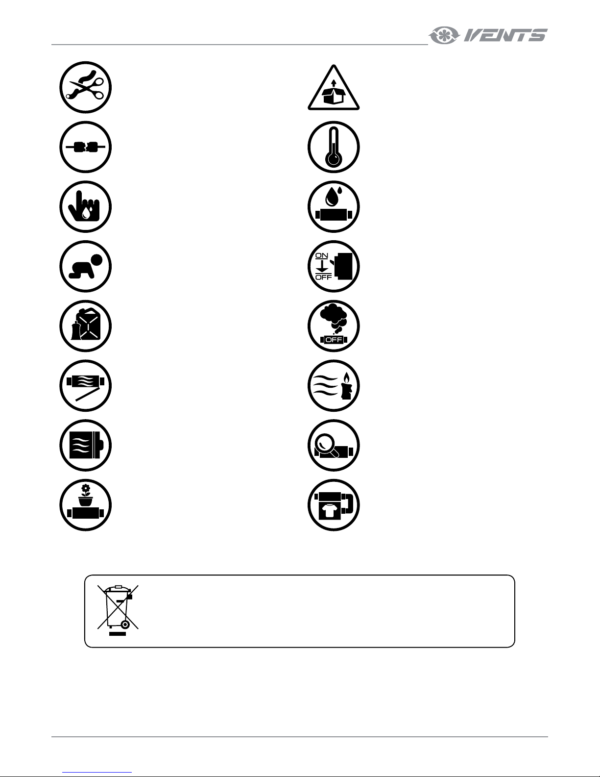
• Do not change the power cable length
at your own discretion. Do not bend
the power cable. Avoid damaging the
power cable. Do not put any foreign
objects on the power cable.
• Unpack the unit with care.
• Do not use damaged equipment or
cables when connecting the unit to
power mains.
• Do not operate the unit outside the
temperature range stated in the user’s
manual. Do not operate the unit in
aggressive or explosive environments.
• Do not touch the unit controls with wet
hands. Do not carry out the installation
and maintenance operations with wet
hands.
• Do not wash the unit with water. Protect
the electric parts of the unit against
ingress of water.
• Do not allow children to operate the
unit.
• Disconnect the unit from power mains
prior to any technical maintenance.
• Do not allow children to operate the
unit.
• When the unit generates unusual
sounds, odour, or emits smoke,
disconnect it from power supply and
contact the Seller
• Do not open the unit during operation.
• Do not direct the air flow produced by
the unit towards open flame or ignition
sources.
• Do not block the air duct when the unit
is switched on.
• In case of continuous operation of the
unit, periodically check the security of
mounting.
• Do not sit on the unit and avoid placing
foreign objects on it.
• Use the unit only for its intended
purpose.
THE PRODUCT MUST BE DISPOSED SEPARATELY AT THE END OF ITS SERVICE LIFE.
DO NOT DISPOSE THE UNIT AS UNSORTED MUNICIPAL WASTE.
Page 4
4
CBF DC
www.ventilation-system.com
PURPOSE
The centrifugal ceiling extract fan CBF DC is designed for extract ventilation of small to medium-sized premises.
The unit is rated for continuous operation.
Transported air must not contain any flammable or explosive mixtures, evaporation of chemicals, sticky substances, fibrous materials,
coarse dust, soot and oil particles or environments favourable for the formation of hazardous substances (toxic substances, dust,
pathogenic germs).
THE UNIT SHOULD NOT BE OPERATED BY CHILDREN OR PERSONS WITH REDUCED
PHYSICAL, MENTAL, OR SENSORY CAPACITIES, OR THOSE WITHOUT THE APPROPRIATE
TRAINING. THE UNIT MUST BE INSTALLED AND CONNECTED ONLY BY PROPERLY
QUALIFIED PERSONNEL AFTER THE APPROPRIATE BRIEFING.
THE CHOICE OF UNIT INSTALLATION LOCATION MUST PREVENT UNAUTHORIZED
ACCESS BY UNATTENDED CHILDREN.
THE UNIT MUST NOT BE OPERATED IN KITCHEN PREMISES.
DELIVERY SET
NAME QUANTITY
Fan 1 pc.
LED lamp (for fans with the Light option) 2 pcs.
Cable gland 1 pc.
Mounting bracket 4 pcs.
Fastening kit 1 pc.
User’s manual 1 pc.
Packing box 1 pc.
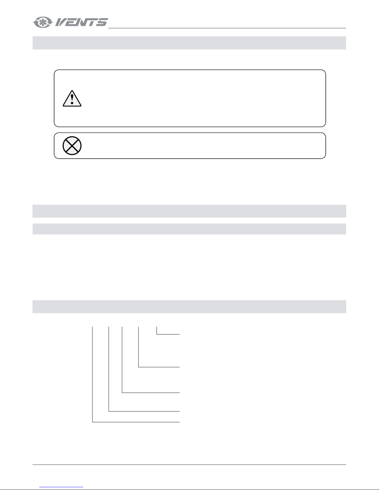
DESIGNATION KEY
CBF 110 DC Light TP
Additional options
T : timer
TH : humidity sensor and timer
TP : motion sensor and timer
Basic options
_ : no integrated light
Light : integrated LED light
Motor type
DC : multi-speed motor
Rated air capacity (CFM)
Fan series
CBF : centrifugal ceiling fan
Page 5
5
www.ventilation-system.com
TECHNICAL DATA
The unit is designed for indoor application at ambient temperature from +1 °C up to +40 °C at max. RF 80 %.
Ingress protection rating against access to hazardous parts and water ingress is IPX4.
The unit design is constantly being improved, so some models may be slightly different from those ones described in this manual..
CBF150 DC T/TH/TP
CBF110 DC T/TH/TP
A
E
H
Ød
ØD
L2
L1
B
C
A
E
H
BL1
L2
Ød
ØD
h
C
b
a
A
E
C
B
ØD
H
h
L1
A
E
C
h
B
H
L1
ØD
b
a
CBF110 DC Light T/TH/TP CBF150 DC Light T/TH/TP
h
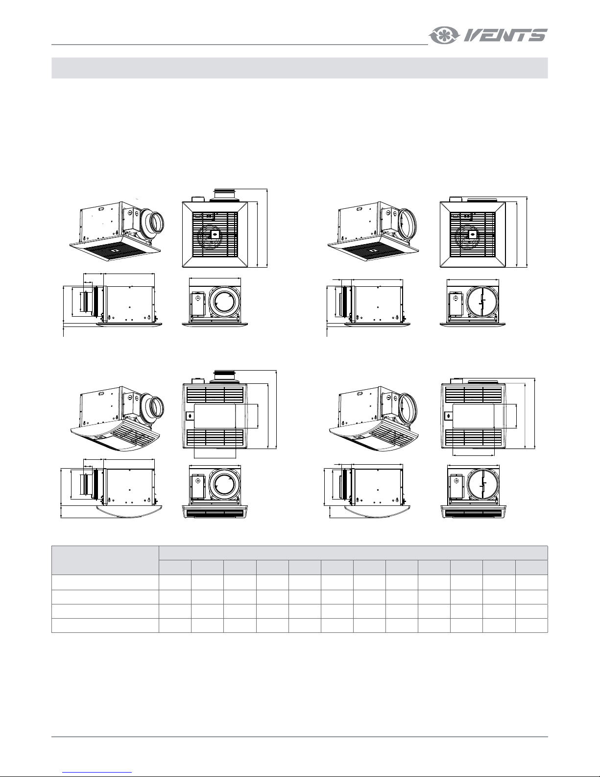
OVERALL AND CONNECTION DIMENSIONS OF THE FANS
MODEL
DIMENSIONS, mm
D d L1 L2 A B C E H h a b
CBF 110 DC T/TH/TP 149 98 100 45 330 258 260 395 188 18 - -
CBF 110 DC Light T/TH/TP 149 98 100 45 330 258 260 395 188 62 208 123
CBF 150 DC T/TH/TP 149 - 50 - 330 258 260 395 188 18 - -
CBF 150 DC Light T/TH/TP 149 - 50 - 330 258 260 395 188 62 208 123
Page 6
6
CBF DC
www.ventilation-system.com
PARAMETER
CBF 110 DC T/TH/TP
CBF 110 DC CBF T/TH/TP
CBF 150 DC T/TH/TP
CBF 150 DC Light T/TH/TP
Frequency [Hz] 50/60 50/60
Supply voltage, [V ] 100-240 100-240
Fan power consumption [W] 19 26
Lamp power [W ]* 2 х 10 2 х 10
RPM [min-1] 1100 1100
Current consumption, 230 V (120 V) [A] 0.18 (0.3) 0.24 (0.39)
Air capacity [m3/h (CFM)] 187 (110) 254 (150)
Noise level, 3 m [dB(A)] (Sones) from 23 (0.3) up 25 (0.7) from 23 (0.3) up 29 (1.0)
Weight [kg] 6.4 (5.3*) 6.2 (5.1*)
IP X4 X4
SEC class B B
* only for the Light modifications
TECHNICAL DATA
CBF 110/150 DC T/TH/TP
CBF 110/150 DC LIGHT T/TH/TP
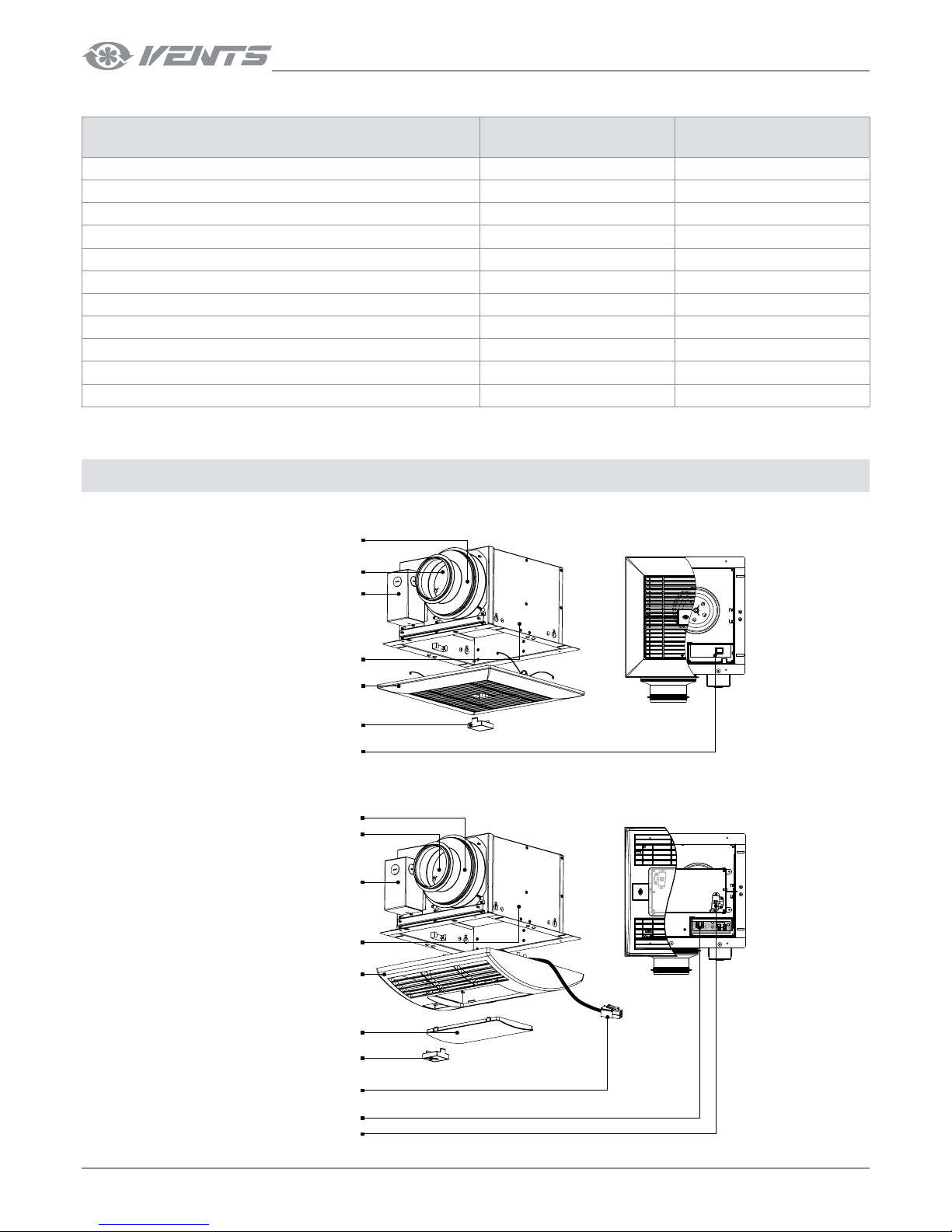
DESIGN AND OPERATING PRINCIPLE
Control unit
Casing
Backdraft damper
Terminal box
Exhaust spigot
Decorative grille
Protective cap / sensor panel
Control unit
Backdraft damper
Terminal box
Exhaust spigot
Decorative grille
Surface-mounted luminaire
Casing
Protective cap / sensor panel
Light sockets
Socket for lamp connection
Page 7
7
www.ventilation-system.com
The fan casing is made of galvanized steel. The fan casing includes an exhaust spigot with a back draft damper to prevent back air flow.
The terminal box comprises the terminals for wiring of the fan and is attached to the fan casing. The decorative grille is fixed to the casing
via the springs inserted to the holders. The front panel is fixed via the grille slots. A single-phase electric motor with a centrifugal impeller
with forward curved blades is fastened inside of the casing. Depending on the fan model the fan may be equipped with a LED lamp, a
timer, a humidity or motion sensor.
Timer T
After an external switch, e.g. a light switch is turned off, the fan is turned on or goes to high speed after countdown of a set turn-on delay
time, adjustable from 0 to 3 minutes.
After the fan is turned off it keeps running for a set turn-off delay time, adjustable from 1 to 90 minutes and the reverts to the initial
operation status.
Motion sensor TP
In case of activation of the motion sensor the fan turns on or switches to the higher speed.
After no motion is detected more the fan keeps running for a set turn-off delay time, adjustable from 1 to 90 minutes, and the reverts to
the initial operation status.
Humidity sensor TH
If the indoor humidity exceeds the set humidity point adjustable from 50 % up to 90 %, the fan either turns on or goes to the higher
speed.
After indoor humidity drops down the fan keeps running for a set turn-off delay time, adjustable from 1 to 90 minutes and the reverts to
the initial operation status.
MOUNTING AND SETUP
READ THE USER'S MANUAL BEFORE INSTALLING THE UNIT.
The fan is a component part and is not designed for stand-alone operation.
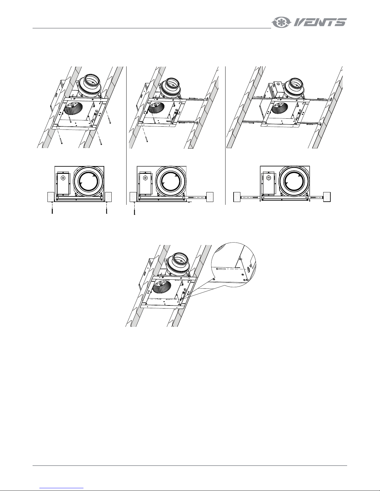
The fan is constructed for ceiling installation in the floor slab and fixation to the inter joist with the distance between the ceiling joists
from 270 up to 680 mm using the removable fixing brackets or the fastening holes in the fan casing.
The installation place must be in compliance with local construction norms for units of this type.
Check the fan for mechanical damages prior to mounting .
Make sure that the casing comprises no foreign objects, such as paper or foil.
While mounting the fan sufficient service access for maintenance or repair operations must be provided.
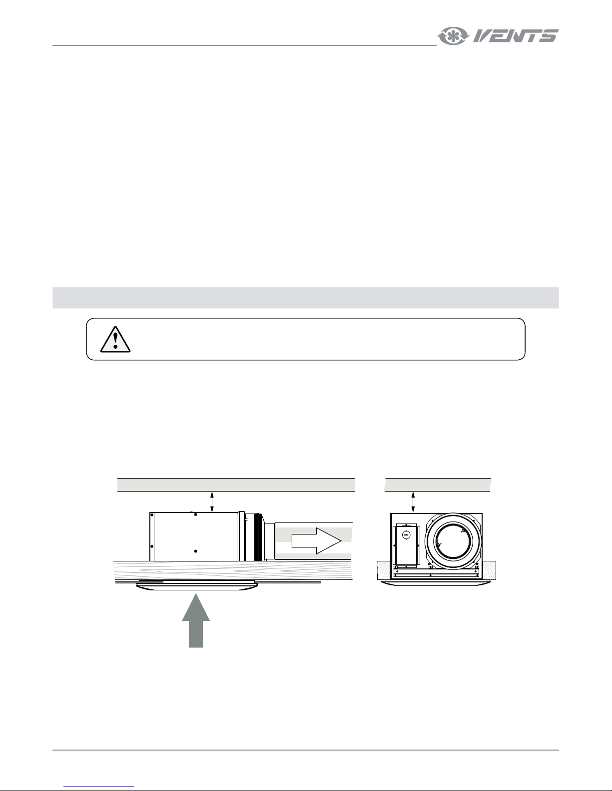
The minimum gap between the fan and the ceiling is 5 mm.
L = 5 mm (min) L = 5 mm (min)
Page 8
8
CBF DC
www.ventilation-system.com
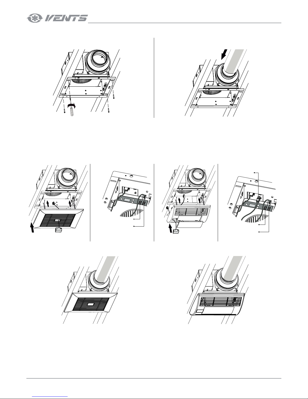
MOUNTING STEPS
1. Attach the fan to the interjoist using the screws. 2. Connect the fan of a required diameter.
3. Connect the LED lamps (included in the delivery set) for the Light models.
Option: connect the humidity sensor or the motion sensor (specially ordered accessory).
For the Light models: connect the power socket of the LED lamp and the respective sockets in the terminal box.
For the TH models with a humidity sensor: remove the protective cap from the grille prior to its installation.
Route the contact socket of the sensor TH or TP via the opening in the grille and connect the sensor socket to the respective contact
socket on the control unit.
Fix the sensor in the grille opening and cover the opening with a protective cap.
Connection socket
of the humidity sensor
Connection socket
of the motion sensor
Connection socket
of the LED lamp
Connection socket
of the humidity sensor
Connection socket
of the motion sensor
4. Install the decorative grille on the fan casing using the holders on the casing.
Page 9
9
www.ventilation-system.com
Side fixation
to one of the ceiling joists
Installation
between the ceiling joists
Fixation between
the ceiling joists using the mounting brackets
Additional fastening holes in the fan casing may be used for mounting purposes
BASIC FAN INSTALLATION OPTIONS
Page 10
10
CBF DC
www.ventilation-system.com
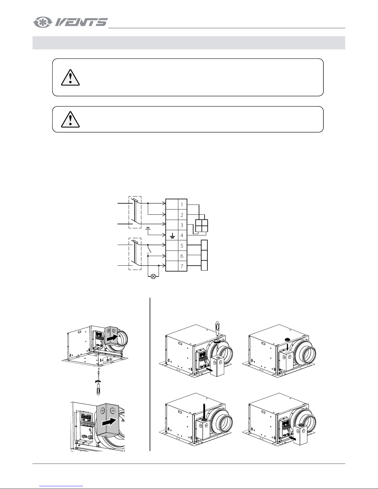
CONNECTION TO POWER MAINS
DISCONNECT THE UNIT FROM POWER MAINS PRIOR TO ANY OPERATIONS.
THE UNIT MUST BE CONNECTED TO POWER MAINS BY A QUALIFIED ELECTRICIAN.
THE RATED ELECTRICAL PARAMETERS OF THE UNIT ARE SHOWN ON THE RATING
PLATE.
ANY TAMPERING WITH THE INTERNAL CONNECTIONS IS PROHIBITED AND WILL VOID
THE WARRANTY.
The fan is rated for connection to single-phase ac 100-240 V/ 50/ (60) Hz power supply.
The fan must be connected to power mains using durable, insulated and heat-resistant conductors (cables and wires) via the circuit
breaker QF integrated into the house cabling system.
The external circuit breaker installation place must ensure unhampered access for emergency shutdown of the unit.
WIRING DIAGRAMS
ACCESS TO THE TERMINAL BOX FOR WIRING THE FAN
L2
L1
N
L
N
LT
N
L
N
L
QF
100-240 V
50 (60) Hz
100-240 V
50 (60) Hz
1234567
LIGHT
(contact socket is available only for
the models with LED light)
FAN
Х1QF
Remove the decorative grille.
For accessing the connection terminals
loosen the screw on the terminal box
lid and take the lid off.
Remove the protective cap and install the cable gland.
Page 11
11
www.ventilation-system.com
CONTROL
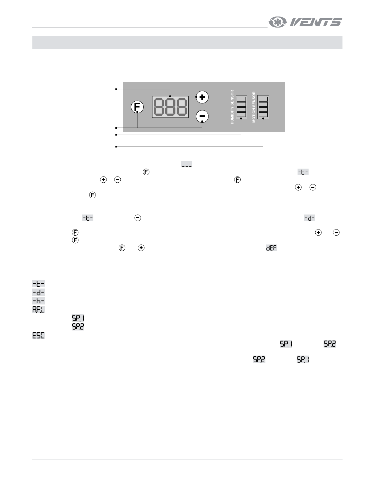
MICROPROCESSOR CONTROL UNIT WITH INDICATION
Indicator
Buttons
Connection
socket for humidity sensor
Connection
socket for motion sensor
The DC fan motor is operated by the microprocessor control unit. The front panel of the control unit comprises a light indicator, control
buttons and two sockets for connection of the humidity sensor and motion sensor.
After the fan is connected to power supply, the indicator displays
for two seconds. After that the light indicator goes off and the fan
starts operating in a set mode. Once the button
is pressed, the indicator displays the turn-off delay timer setting , the first setup
menu entry. Use the buttons
or to navigate in the setup menu. Press the button to select a current entry in the setup menu.
After that the indicator displays the selected parameter value (e.g., turn-off delay timer setting). Use the buttons
or to edit the
setting. Press the button
to come back to the setup menu. If no button is pressed for 60 seconds, the indicator goes down.
Example
The indicator displays
. Once the button is pressed, the setup menu list goes one position down and the symbol is displayed
(refer to the setup menu).
Once the button
is pressed, the indicator displays the turn-on delay timer setting, which can be edited with the buttons and .
Once the button
is pressed again, the setup menu is displayed again and the edited value is saved. To reset the menu to the factory
settings press and hold the buttons
and synchronously. In 5 seconds the indicator displays and goes off. The fan keeps
running normally with the factory settings.
INDICATOR SYMBOLS OF THE MICROPROCESSOR CONTROL UNIT
: turn-off delay timer adjustable from 1 to 90 minutes (default setting 15 minutes)
: turn-on delay timer adjustable from 0 to 180 seconds with the increment of 10 seconds (default setting 0)
: humidity set point adjustable from 50% up to 90% (default setting 75%)
: access to submenu of the fan operation mode
Operation mode
: the fan operates without any activation signal from the switch, humidity or motion sensor.
Operation mode
: the fan operates with activation signal from the switch, humidity or motion sensor.
: back to the upper setup menu level.
Once the switch is turned on or the humidity or motion sensor is activated, the fan switches from the mode
to the mode .
After no signal is received more from the sensor in case of the indoor humidity normalization or no motion detection or in case of the fan
shutdown the fan keeps running for a set turn-off delay time and then switches from the mode
to the mode .
Page 12
12
CBF DC
www.ventilation-system.com
MAINTENANCE
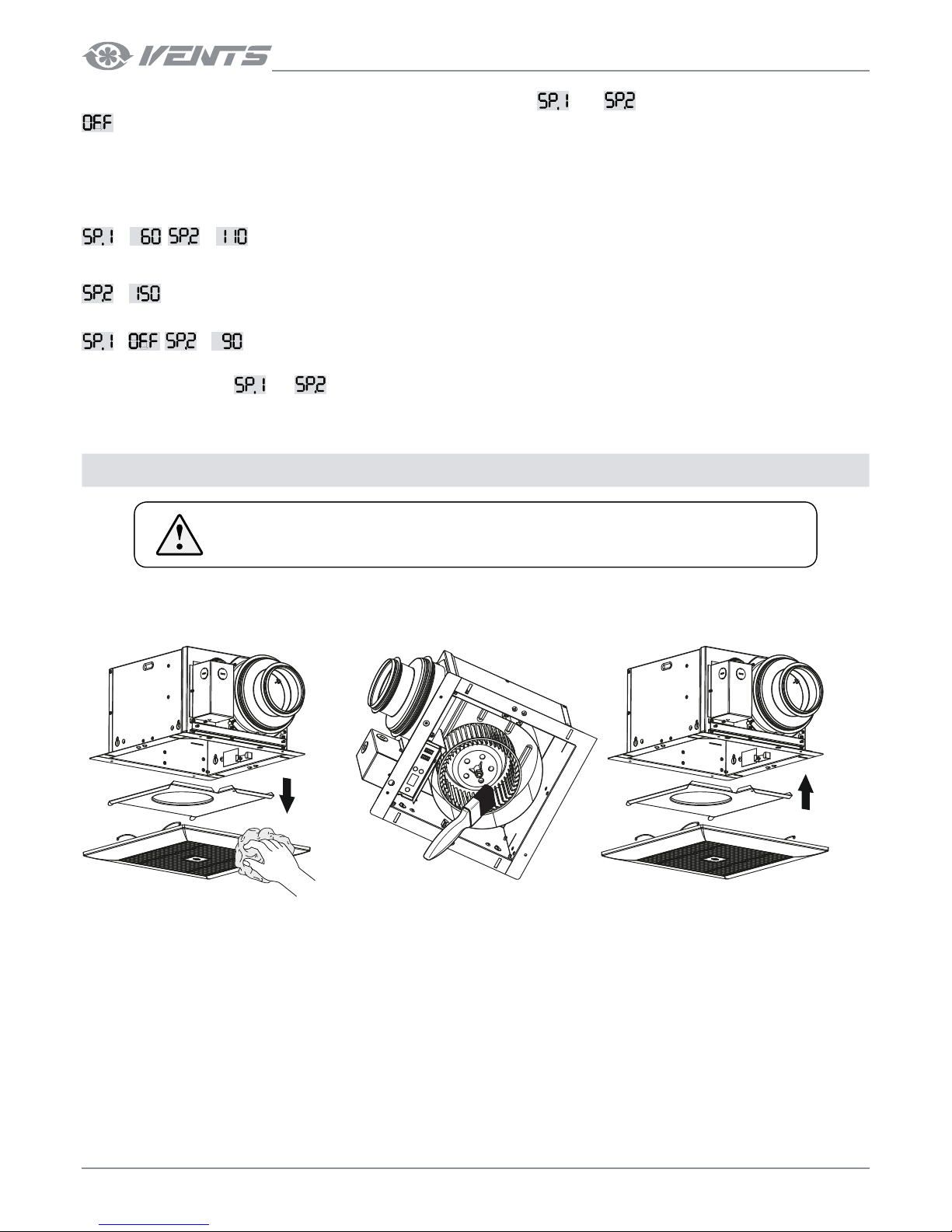
The fan maintenance includes regular cleaning of the surfaces of dust and dirt. Replace the filter as required, but at least every 6 months.
The impeller cleaning is shown below. Clean the impeller blades thoroughly every 6 months.
DISCONNECT THE UNIT FROM POWER SUPPLY BEFORE ANY MAINTENANCE
OPERATIONS.
SETUP OF THE OPERATION MODES AND
: the fan is turned off.
“60”, “70”, “80”, “90”, “100”, “110”, “120”, “130”, “140”, “150”: the fan runs to keep permanent air flow with set air capacity settings. The settings
are displayed in CFM.
The maximum air flow value is limited to 110 or 150 CFM, depending on the fan model.
“120”, “130”, “140” and “150” air flow values are not available for the fan with the air capacity 110 CFM.
Example 1
= , = : with these activated settings the fan runs to keep the air flow 60 CFM. Once the switch is turned on or a
sensor is activated, the fan starts to run with the maximum capacity.
That is a factory setting for the fans with the maximum air capacity 110 CFM.
= is applied for the fans with the maximum air capacity 150 CFM.
Example 2
= , = : with these activated settings the fan is off. Once the switch is turned on or a sensor is activated, the fan starts
running to keep the air flow 90 CFM.
This way by changing the
and parameters you can set a required operation mode.
Page 13
13
www.ventilation-system.com
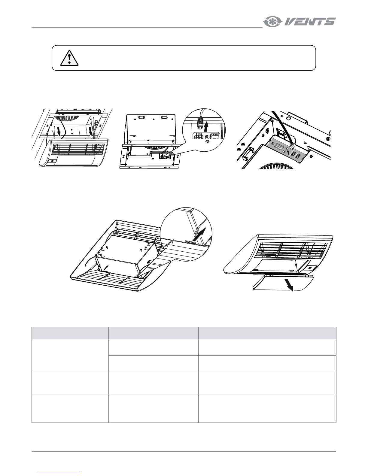
LAMP REPLACEMENT
DISCONNECT THE UNIT FROM POWER SUPPLY BEFORE ANY MAINTENANCE
OPERATIONS.
1. Remove the decorative grille:
• Pull the grille to release the springs from the holders on the casing.
• Take out the lamp power socket from the respective socket on the casing.
• Take out the power socket of the sensors from the respective sockets on the control unit (applicable for TH and TP models).
2. Take off the surface-mounted luminaire.
• Press the holders on the reverse side of the grille frame and take off the surface-mounted luminaire.
3. Replace the lamps.
4. Reassemble the unit in the reverse order.
TROUBLES AND TROUBLESHOOTING
TROUBLE POSSIBLE REASONS TROUBLESHOOTING
The fan does not get started.
No power supply.
Check the electric connections and the operation status of the
circuit breaker.
Motor jam.
Turn the fan off. Troubleshoot clogging of the impeller. Restart
the fan.
Automatic circuit breaker tripping
during the unit turning on.
Over current as a result of short circuit
in the electric circuit leads to tripping of
the circuit breaker.
Disconnect the fan from power supply and contact the product
Seller. Do not turn the fan on again!
Low air flow.
Air ducts or other components of the
ventilation system are clogged. The
impeller is clogged. The air ducts are
damaged. The air dampers are closed.
Clean the air ducts, the impeller and other components of
the ventilation system. Make sure that the air ducts are not
damaged. Make sure that the air dampers and louvre shutters
are open.
Page 14

14
CBF DC
www.ventilation-system.com
STORAGE AND TRANSPORTATION REGULATIONS
• Store the unit in the manufacturer’s original packaging box in a dry closed ventilated premise with temperature range from +5 °C to +
40 °C.
• Storage environment must not contain aggressive vapours and chemical mixtures provoking corrosion, insulation, and sealing
deformation.
• Use suitable hoist machinery for handling and storage operations to prevent possible damage to the unit.
• Follow the handling requirements applicable for the particular type of cargo.
• The unit can be carried in the original packaging by any mode of transport provided proper protection against precipitation and
mechanical damage. The unit can be transported only in the working position.
• Avoid sharp blows, scratches, or rough handling during loading and unloading.
• Prior to the initial power-up after transportation at low temperatures allow the unit to warm up at room temperature for at least
3-4 hours.
Page 15
15
www.ventilation-system.com
MANUFACTURER’S WARRANTY
The manufacturer hereby warrants normal operation of the unit for 24 months after the retail sale date provided the user's observance of
the transportation, storage, installation, and operation regulations.
Should any malfunctions occur in the course of the unit operation through the Manufacturer's fault during the guaranteed period of
operation, the user is entitled to get all the faults eliminated by the manufacturer by means of warranty repair at the factory free of charge.
The warranty repair includes work specific to elimination of faults in the unit operation to ensure its intended use by the user within the
guaranteed period of operation.
The faults are eliminated by means of replacement or repair of the unit components or a specific part of such unit component.
The warranty repair does not include:
• Routine technical maintenance
• Unit installation / dismantling
• Unit setup
To benefit from warranty repair, the user must provide the unit, the user's manual with the purchase date stamp, and the payment
paperwork certifying the purchase.
The unit model must comply with the one stated in the user’s manual.
Contact the Seller for warranty service.
The manufacturer’s warranty does not apply to the following cases:
• User’s failure to submit the unit with the entire delivery package as stated in the user’s manual including submission with
missing component parts previously dismounted by the user.
• Mismatch of the unit model and the brand name with the information stated on the unit packaging and in the user's manual.
• User’s failure to ensure timely technical maintenance of the unit.
• External damage to the unit casing (excluding external modifications as required for installation) and internal components
caused by the user.
• Redesign or engineering changes to the unit.
• Replacement and use of any assemblies, parts and components not approved by the manufacturer.
• Unit misuse.
• Violation of the unit installation regulations by the user.
• Violation of the unit control regulations by the user.
• Unit connection to power mains with a voltage different from the one stated in the user's manual;
• Unit breakdown due to voltage surges in power mains.
• Discretionary repair of the unit by the user.
• Unit repair by any persons without the manufacturer’s authorization.
• Expiration of the unit warranty period.
• Violation of the unit transportation regulations by the user.
• Violation of the unit storage regulations by the user.
• Wrongful actions against the unit committed by third parties.
• Unit breakdown due to circumstances of insuperable force (fire, flood, earthquake, war, hostilities of any kind, blockades).
• Missing seals if provided by the user’s manual.
• Failure to submit the user’s manual with the unit purchase date stamp.
• Missing payment paperwork certifying the unit purchase.
FOLLOWING THE REGULATIONS STIPULATED HEREIN WILL ENSURE A LONG AND
TROUBLEFREE OPERATION OF THE UNIT.
USERS’ WARRANTY CLAIMS SHALL BE SUBJECT TO REVIEW ONLY UPON PRESENTATION
OF THE UNIT, WARRANTY CARD, AND THE USER’S MANUAL WITH THE PURCHASE DATE
STAMP.
Page 16
16
CBF DC
www.ventilation-system.com
SELLER INFORMATION
Seller
Address
Phone Number
E-mail
Purchase Date
This is to certify acceptance of the complete unit delivery with the user’s manual. The warranty terms
are acknowledged and accepted.
Customer’s Signature
Seller’s Stamp
INSTALLATION CERTIFICATE
Installation Company Stamp
The centrifugal ceiling extract fan CBF ______________________ has been connected to power
mains pursuant to the requirements stated in the present user’s manual.
Seller
Address
Phone Number
Installation
Technician’s Full Name
Installation Date: Signature:
The unit has been installed in accordance with the provisions of all the applicable local and national
construction, electrical and technical codes and standards. The unit operates normally as intended by
the manufacturer.
Signature:
WARRANTY CARD
Seller’s Stamp
Un it Type Centrifugal ceiling extract fan
Model CBF _______________________
Serial Number
Manufacture Date
Purchase Date
Warranty Period
Seller
ACCEPTANCE CERTIFICATE
Un it Type Centrifugal ceiling extract fan
Model CBF _______________________
Serial Number
Manufacture Date
Quality Inspector’s
Stamp
The product is in compliance with EU norms and standards on low voltage guidelines and electromagnetic compatibility. We hereby
declare that the product complies with the provisions of Electromagnetic Council Directive 2014/30/EU, Low Voltage Directive 2014/35/
EU and CE-marking Directive 93/68/EEC.
Page 17

17
www.ventilation-system.com
Page 18

18
CBF DC
www.ventilation-system.com
Page 19

19
www.ventilation-system.com
Page 20

V166EN-01
 Loading...