

Page 1
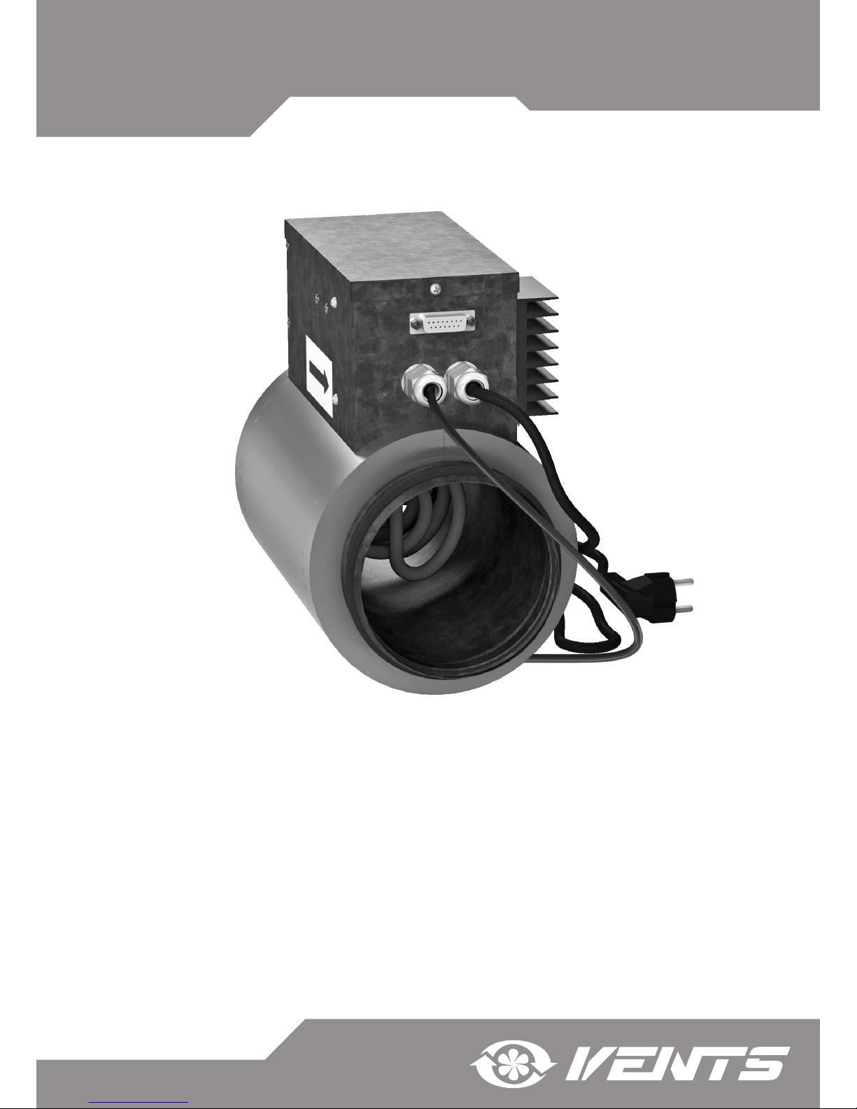
USER’S MANUAL
DUCT HEATER FOR SUPPLY AIR POSTHEATING
WITH EXTERNAL CONTROL
NKD Series
NKD-125
NKD-160
NKD-200
Page 2

2
CONTENTS
Safety requirements 3
Purpose 5
Delivery set 5
Designation key 5
Technical data 5
Unit design and operating logic 6
Mounting and set-up 7
Wiring diagram 8
Technical maintenance 9
Storage and transportation regulations 9
Manufacturer's warranty 10
Acceptance certicate 11
Seller information 11
Installation certificate 11
Warranty card 11
Page 3
www.ventilation-system.com
3
This user’s manual consisting of the technical details, operating instructions and technical specication covers the installation
and mounting of the NKD duct heater for supply air post-heating (hereinafter «the heater» or «the unit» as mentioned in the
«Safety Requirements» and «Manufacturer’s Warranty» sections as well as in warnings and information blocks).
SAFETY REQUIREMENTS
• Read the user’s manual carefully prior to installing and operating the unit.
• Fulfil the user’s manual requirements as well as the provisions of all the applicable local and national construction, electrical
and technical norms and standards.
• The warnings contained in the user’s manual must be considered most seriously since they contain vital personal safety
information.
• Failure to follow the rules and safety precautions noted in this user’s manual may result in an injury or unit damage.
• After a careful reading of the manual, keep it for the entire service life of the unit.
• While transferring the unit control the User’s manual must be turned over to the receiving operator.
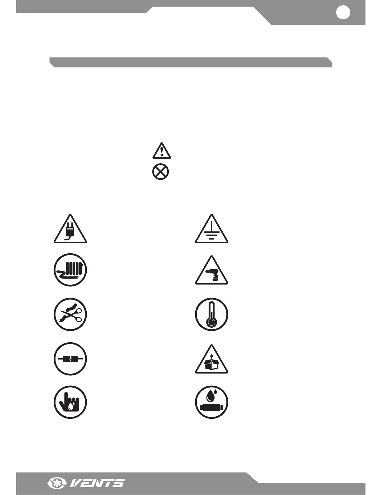
Symbol legend:
WARNING!
DO NOT!
UNIT MOUNTING AND OPERATION SAFETY PRECAUTIONS
• Disconnect the unit from power mains
prior to any installation operations.
• The unit must be grounded!
• Do not lay the power cable of the
unit in close proximity to heating
equipment.
• While installing the unit follow the
safety regulations specific to the use
of electric tools.
• Do not change the power cable length
at your own discretion.
• Do not bend the power cable.
• Avoid damaging the power cable.
• Do not put any foreign objects on the
power cable.
• Do not operate the unit outside the
temperature range stated in the user's
manual.
• Do not operate the unit in aggressive
or explosive environments.
• Do not use damaged equipment or
cables when connecting the unit to
power mains.
• Unpack the unit with care.
• Do not touch the unit controls with
wet hands.
• Do not carry out the installation and
maintenance operations with wet
hands.
• Do not wash the unit with water.
• Protect the electric parts of the unit
against ingress of water.
Page 4
4
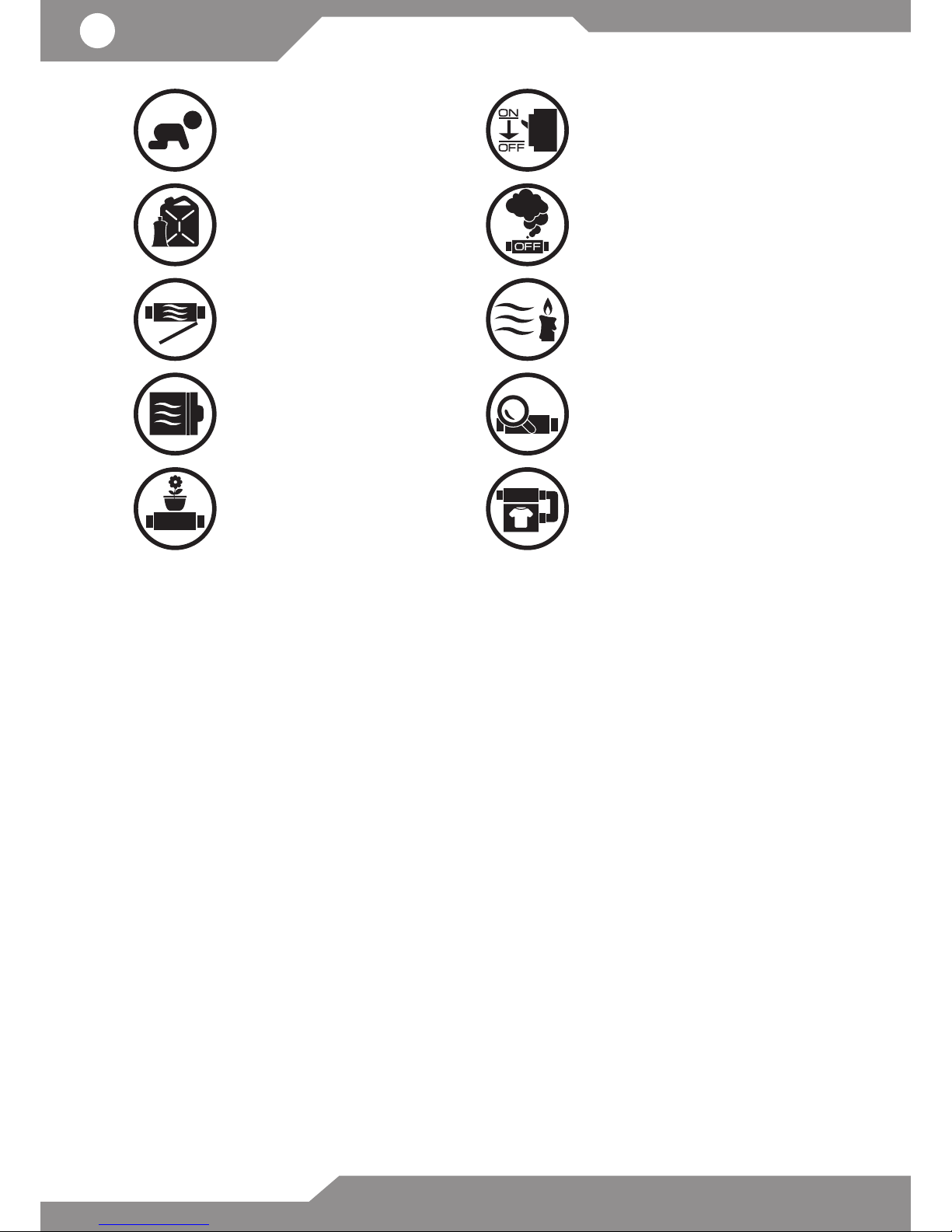
• Do not allow children to operate the
unit.
• Disconnect the unit from power mains
prior to any technical maintenance.
• Do not store any explosive or highly
flammable substances in close proximity
to the unit.
• When the unit generates unusual
sounds, odour or emits smoke
disconnect it from power supply and
contact the Seller.
• Do not open the unit during operation.
• Do not direct the air flow produced by
the unit towards open flame or ignition
sources.
• Do not block the air duct when the unit
is switched on.
• In case of continuous operation of the
unit periodically check the security of
mounting.
• Do not sit on the unit and avoid placing
foreign objects on it.
• Use the unit only for its intended
purpose.
Page 5
www.ventilation-system.com
5
PURPOSE
The heater is designed for integration into a ventilation system and joint operation with an air handling unit equipped with
a control system used to switch on the heater and control its operation.
The heater maintains the supply duct air temperature at a point set by the unit controller.
THE UNIT MAY NOT BE OPERATED BY CHILDREN OR PERSONS WITH REDUCED
PHYSICAL, MENTAL OR SENSORY CAPACITIES, OR LACKING THE APPROPRIATE
TRAINING.
THE UNIT MUST BE INSTALLED AND CONNECTED ONLY BY PROPERLY QUALIFIED
PERSONNEL AFTER THE APPROPRIATE BRIEFING.
THE CHOICE OF UNIT INSTALLATION LOCATION MUST PREVENT UNAUTHORIZED
ACCESS BY UNATTENDED CHILDREN.
DELIVERY SET
Heater 1 item
Connecting cable with DB-15M connectors 1 item
User's manual 1 item
Packing box 1 item
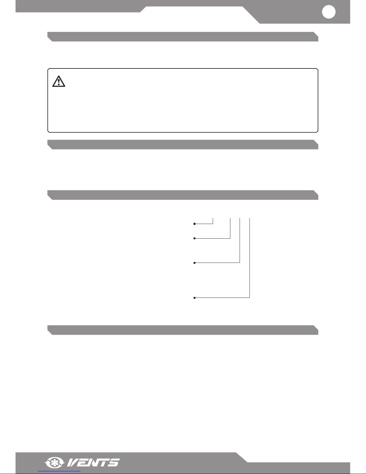
DESIGNATION KEY
NKD X-X-X
Connecting air duct diameter [mm]
125
160
200
Unit Type
NKD duct heater for supply air post-heating
Heater power consumption [kW]
0,6
0,8
1,2
1,7
2,0
Phases
1 - single-phase
TECHNICAL DATA
The heater is rated for indoor application with the ambient temperature ranging from -30°C up to +40°C and relative
humidity up to 80 %.
The heater is rated for connection to single-phase AC 230 V/50 (60) Hz.
The recommended minimum air flow speed in the air duct is 1.5 m/s.
Hazardous parts access and water ingress protection rating: IP 40
The heater design is regularly improved, so some models may slightly dier from those ones described in this manual.
Page 6
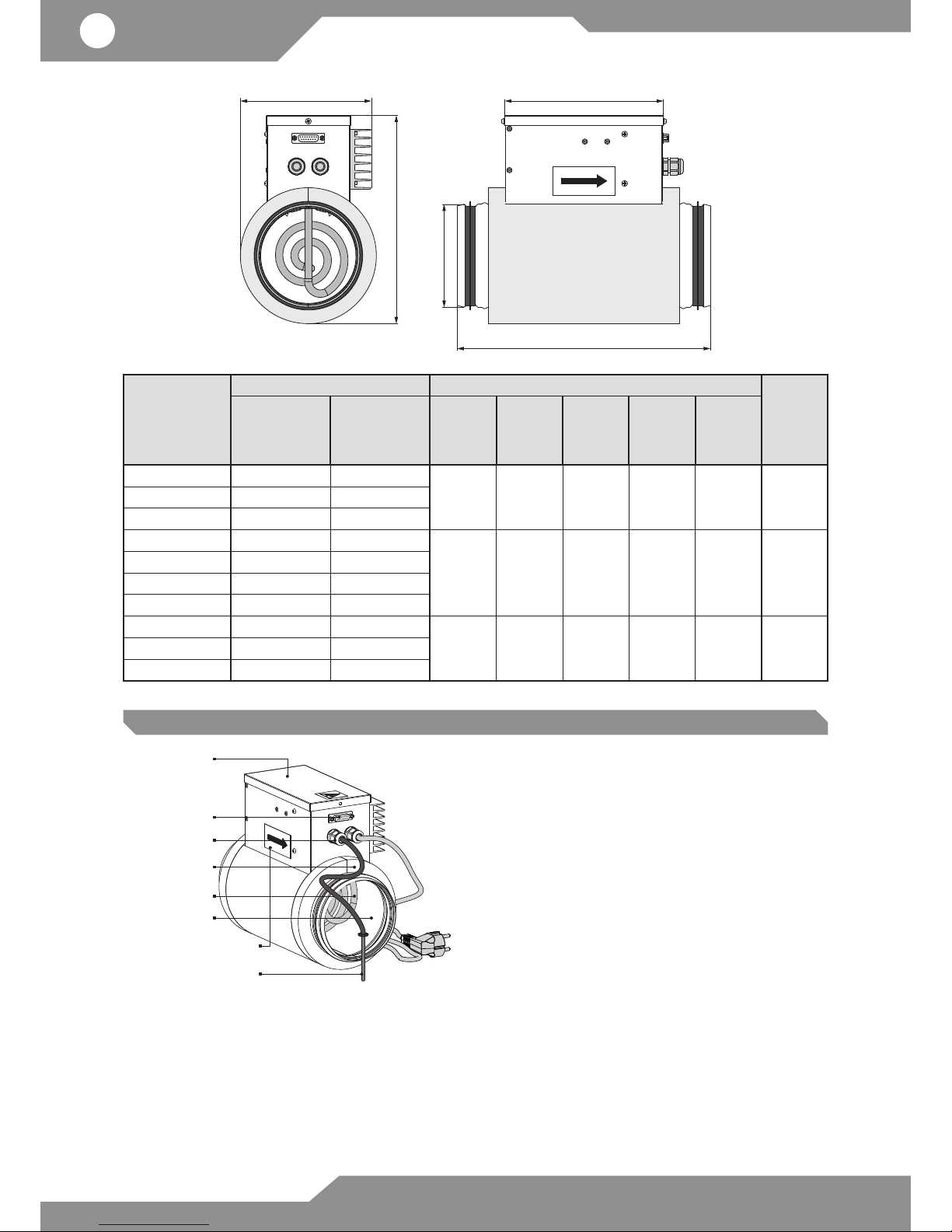
6
L1
H
L
B
ØD
Model
Technical data Dimensions [mm]
Weight
[kg]
Power
consumption of
electric heating
elements [kW]
Current [A] Ø D В H L L1
NKD 125-0,6-1 0,6 2,6
NKD 125-0,8-1 0,8 3,5 124 155 251 306 190 2,1
NKD 125-1,2-1 1,2 5,2
NKD 160-0,8-1 0,8 3,5
NKD 160-1,2-1 1,2 5,2
NKD 160-1,7-1 1,7 7,4 159 175 293 306 190 2,5
NKD 160-2,0-1 2,0 8,7
NKD 200-1,2-1 1,2 5,2
NKD 200-1,7-1 1,7 7,4 199 195 337 306 190 2,8
NKD 200-2,0-1 2,0 8,7
DESIGN AND OPERATING LOGIC
Control box
Air ow
direction
DB-15F connector
Cable glands
Electric heating
element
Heat insulation
Temperature sensor TE5
Casing
The control box is rigidly fixed to the heater casing and covered
with a detachable cover.
The control box incorporates:
• fasteners for the electric heating element;
• electric components for connection to power supply;
• ground screw clamp;
• manual reset thermal switch TK-90;
• automatic reset thermal switch TK-50;
The cable gland for power cable, the cable gland for the supply
air temperature sensor as well as the connector for connection to
the air handling unit are located on the front panel of the control
box.
The tubular electric heating element is located inside the
casing.
The casing, the connecting box and the heater cover are made
of galvanized steel.
The heater casing is heat-insulated with 20 mm mineral wool layer.
Connect the NKD heater and the air handling unit using the cable with DB-15 connectors and connect it to the power mains.
The electric heating element heats the air in the supply air duct.
Smooth control of air heating is performed with a signal given from the unit controller to the semiconductor regulator.
In case of overheating the thermostats switch the heater off.
Page 7
www.ventilation-system.com
7
MOUNTING AND SETUP
INSTALLATION SHALL ONLY BE PERFORMED BY A PROFESSIONAL ELECTRICIAN
QUALIFIED FOR UNASSISTED OPERATIONS WITH ELECTRICAL INSTALLATIONS AND
POSSESSING THE REQUIRED TOOLS AND MATERIALS.
FULFIL THE USER’S MANUAL REQUIREMENTS AS WELL AS THE PROVISIONS OF ALL
THE APPLICABLE LOCAL AND NATIONAL CONSTRUCTION, ELECTRICAL AND TECHNICAL
NORMS AND STANDARDS. THE HEATER MUST BE GROUNDED!
THE INSTALLATION PLACE MUST PROVIDE SUFFICIENT SERVICE ACCESS.
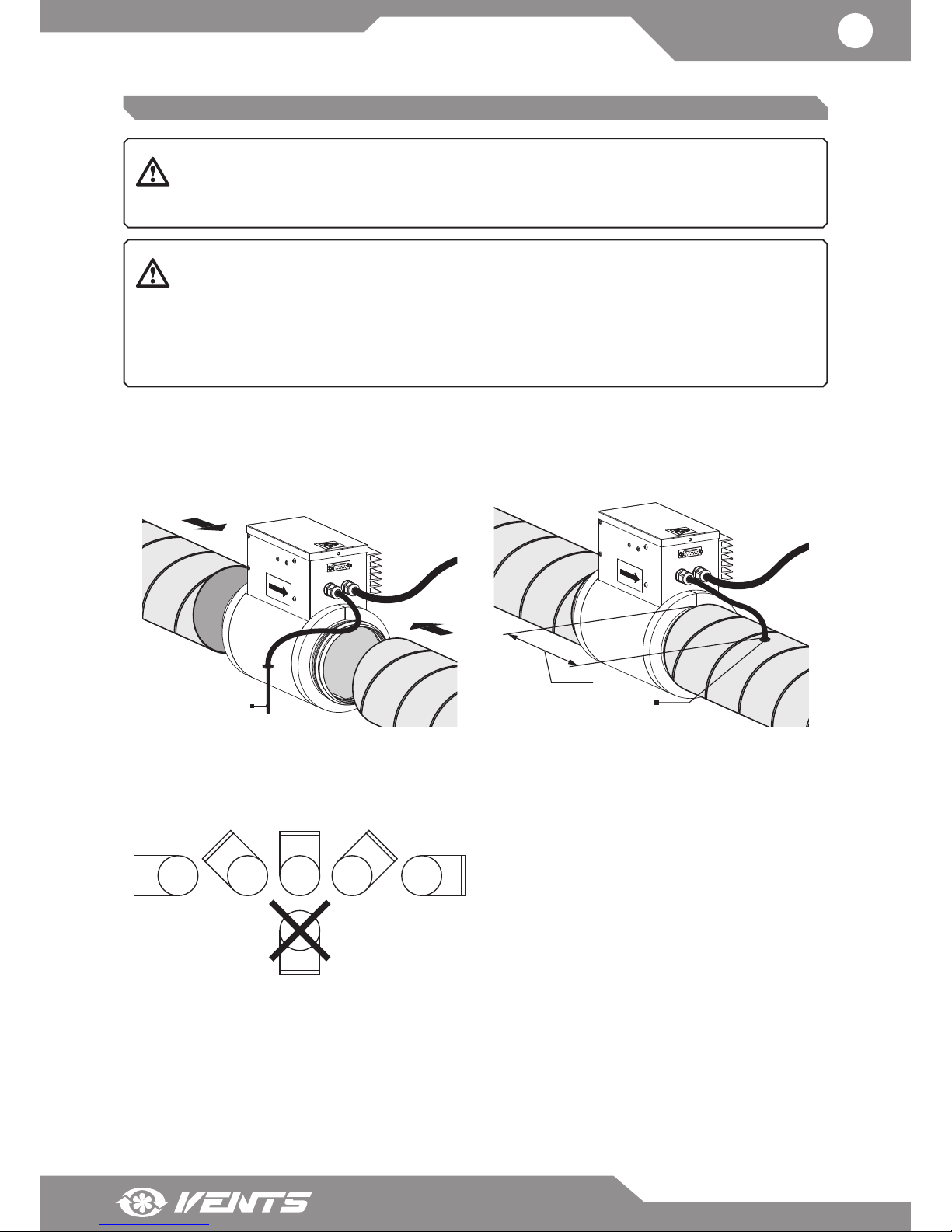
1. 1. Connect air ducts to the heater
The heater is designed for inline mounting in the air duct both
horizontally and vertically.
2. Install the duct temperature sensor TE5
The sensor is mounted in the supply air duct downstream of
the heater at the distance of min 1 m from the heater.
Temperature
sensor TE5
Temperature sensor TE5
min 1m
Heater position
In case of horizontal mounting position the control box cover
must be directed upwards only.
The maximum deviation angle is 90°. The control box cover
may not be positioned downwards!
Page 8
8
CONNECTION TO POWER MAINS
DISCONNECT THE UNIT FROM POWER MAINS PRIOR TO ANY OPERATIONS. THE FAN
MUST BE CONNECTED TO POWER MAINS BY A QUALIFIED ELECTRICIAN. THE RATED
ELECTRICAL PARAMETERS OF THE UNIT ARE GIVEN ON THE MANUFACTURER’S LABEL.
ANY TAMPERING WITH THE INTERNAL CONNECTIONS IS PROHIBITED AND WILL VOID
THE WARRANTY.
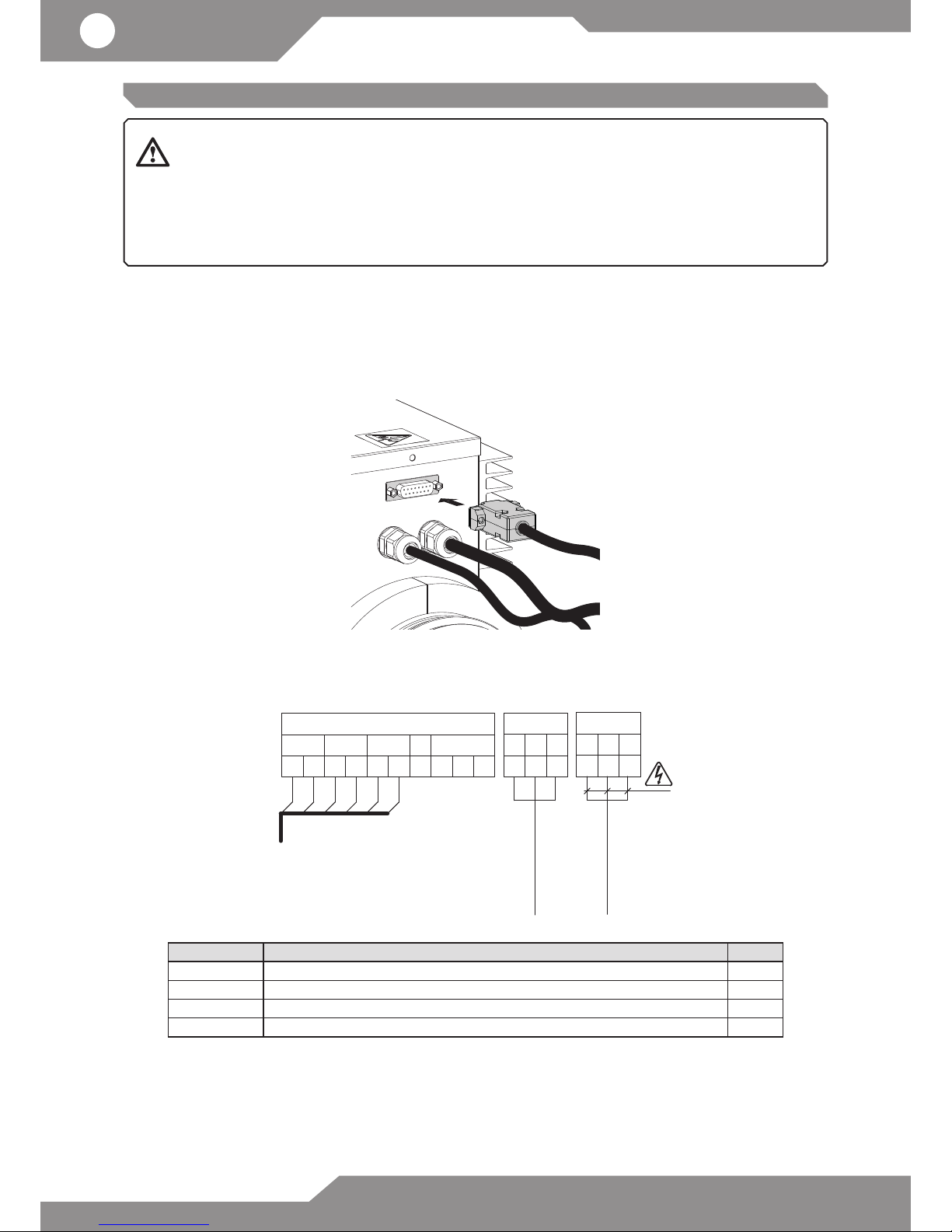
Temperature sensor TE5
The TE5 sensor is connected to the heater terminals by the manufacturer. The sensor cable is routed through the сable gland
at the casing of the heater.
Connection of the heater with the air handling unit.
The connection must be completed prior to connection of the heater and the air handling unit to power mains!
Connect the heater and the air handling unit using the cable with DB-15M connectors through the DB-15F external connectors
located on the heater or on the air handling unit.
HEATER CONNECTION TO POWER MAINS
Connect the heater to AC single-phase 230 V / 50 (60) Hz power mains using a pre-wired power cable with a Euro Plug XP.
Wiring diagram
10 11
External connector DB-15
Heating
signal
TE5
1 2
3 4 5 6
TK-50
TK-90
9
to the unit
...
TE5
6 5 4
Out
Gnd
+
U
Supply air
temperature sensor
230 VAC
ELECTRIC SHOCK HAZARD!
3 2 1
PE
N
L
Power input
230 VAC
Design. Name Type
ТК‐50 Contacts of automatic reset thermal switch with response temperature +50 °C. N0
ТК‐90 Contacts of manual reset thermal switch with response temperature +90 °C N0
Heating signal Heater control triac input signal VAC
TE5 Supply air sensor signal VDC
Page 9
www.ventilation-system.com
9
TECHNICAL MAINTENANCE
DISCONNECT THE UNIT FROM POWER MAINS PRIOR TO ANY MAINTENANCE
OPERATIONS.
PROTECT THE HEATER FROM WATER INGRESS! DO NOT USE AGGRESSIVE SOLVENTS AND
SHARP OBJECT FOR CLEANING.
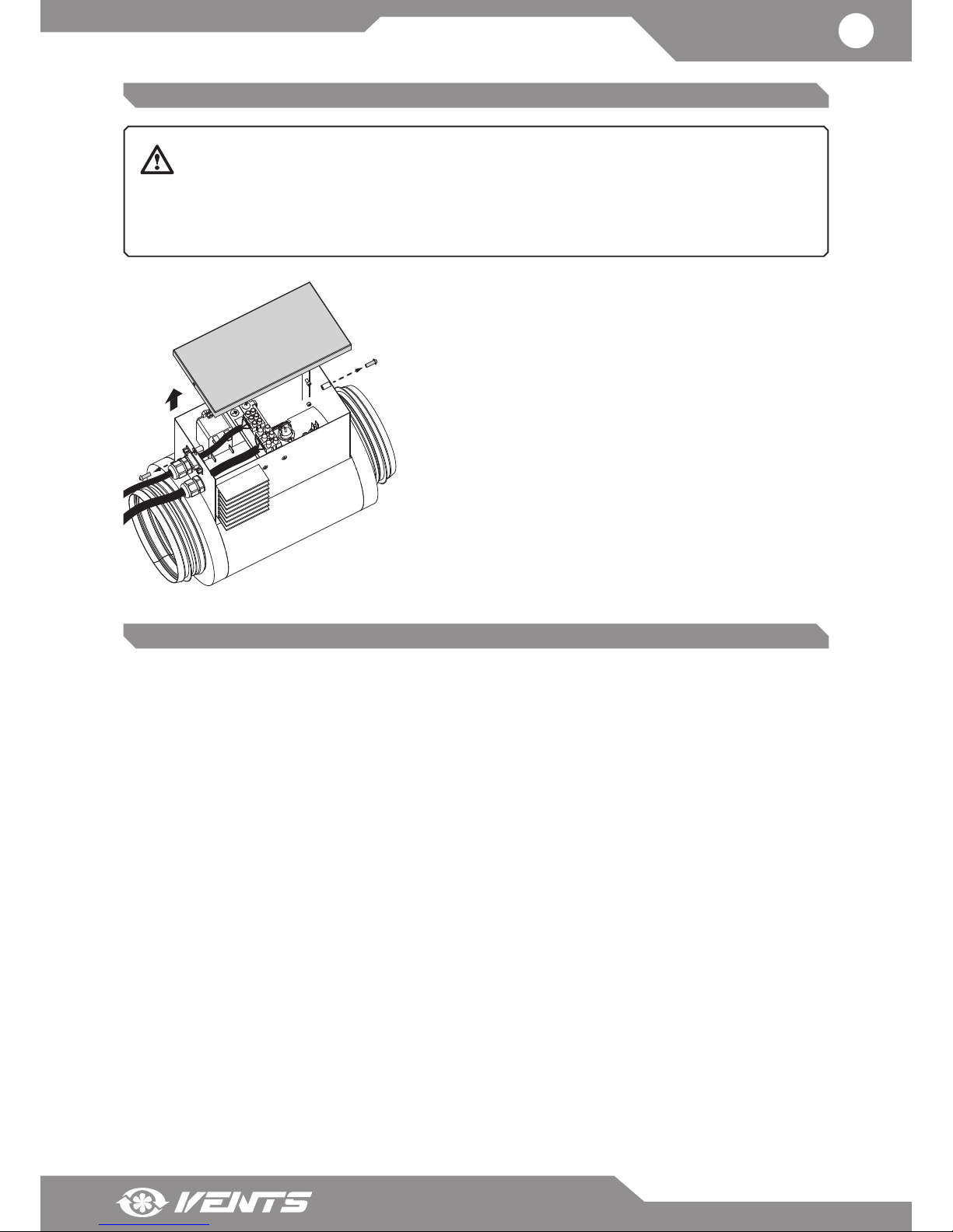
The heater maintenance includes:
• Inspection of screw connections as well as rivet and welded
joints.
• Inspection of tightening of ground screw clamps and electric
connections.
• Inspection of the wire terminal connections.
• Cleaning of the electric heating elements of dust and dirt.
STORAGE AND TRANSPORTATION REGULATIONS
Store the unit in the manufacturer’s original packing box in a dry closed ventilated premise with temperature range from +5 °C to + 40
°C.
Storage environment must not contain aggressive vapours and chemical mixtures provoking corrosion, insulation and sealing
deformation.
Use hoist machinery for handling and transportation to prevent possible mechanical damages of the unit.
Follow the applicable moving regulations specific to the particular cargo type while loading and unloading.
The unit can be transported in the original packing by any mode of transport without limitation provided proper protection against
precipitation and mechanical damage.
Avoid any mechanical shocks and strokes during handling operations.
Page 10
10
MANUFACTURER’S WARRANTY
The manufacturer hereby warrants normal operation of the unit for 24 months after the retail sale date provided the user’s
observance of the transportation, storage, mounting and operation regulations.
Should any malfunctions occur in the course of the unit operation through the Manufacturer’s fault during the guaranteed period
of operation the user is entitled to elimination of faults by the manufacturer by means of warranty repair at the factory free of charge.
The warranty repair shall include work specific to elimination of faults in the unit operation to ensure its intended use by the user
within the guaranteed period of operation.
The faults are eliminated by means of replacement or repair of the unit components or a specific part of such unit component.
The warranty repair does not include:
• routine technical maintenance
• unit installation / dismantling
• unit setup
To benefit from warranty repair the user must provide the unit, the user’s manual with the purchase date stamp and the payment
document certifying the purchase.
The unit model must comply with the one stated in the user’s manual.
Contact the Seller for warranty service.
The manufacturer’s warranty does not apply to the following cases:
• User’s failure to submit the unit with the entire delivery package as stated in the user’s manual including submission with
missing component parts previously dismounted by the user.
• Mismatch of the unit model and the brand name with the information stated on the unit packing and in the user’s manual.
• User’s failure to ensure timely technical maintenance of the unit.
• External damage to the unit casing (excluding external modifications as required for installation) and internal components
caused by the user.
• Redesign or engineering changes to the unit.
• Replacement and use of any assemblies, parts and components not approved by the manufacturer.
• Unit misuse.
• User’s violation of the unit installation regulations.
• User’s violation of the unit control regulations.
• Unit connection to the power mains with a voltage different from the one stated in the user’s manual.
• Unit breakdown due to voltage surges in the power mains.
• Discretionary repair of the unit by the user.
• Unit repair by any persons without the manufacturer’s authorization.
• Expiration of the unit warranty period.
• User’s violation of the unit transportation regulations.
• User’s violation of the unit storage regulations.
• Wrongful actions against the unit committed by third parties.
• Unit breakdown due to circumstances of insuperable force (fire, flood, earthquake, war, hostilities of any kind, blockades).
• Missing seals if provided by the user’s manual.
• Failure to submit the user’s manual with the unit purchase date stamp.
• Missing payment document certifying the unit purchase.
FOLLOWING THE REGULATIONS STIPULATED HEREIN WILL ENSURE A LONG AND
TROUBLEFREE OPERATION OF THE UNIT.
USERS’ CLAIMS SHALL BE A SUBJECT TO REVIEW ONLY UPON PRESENTATION OF
THE UNIT, THE PAYMENT DOCUMENT AND THE USER’S MANUAL WITH THE SALE
DATE STAMP.
Page 11
www.ventilation-system.com
11
ACCEPTANCE CERTIFICATE
Unit Type Duct heater for supply air post-heating
Model
NKD-
Serial Number
Manufacture Date
is recognized as serviceable.
Quality Inspector’s
Stamp
SELLER INFORMATION
Seller
Address
Phone Number
E-mail
Purchase Date
This is to certify acceptance of the complete unit delivery with the user’s manual. The warranty
terms are acknowledged and accepted.
Customer's Signature
Seller’s Stamp
MOUNTING CERTIFICATE
The unit has been connected to power mains pursuant to the requirements stated in the
present user’s manual.
Company Name
Address
Phone Number
Installation
Technician's Full Name
Installation Date: Signature:
"The heater has been installed in accordance with the provisions of all the applicable local
and national construction, electrical and technical codes and standards.
The unit operates normally as intended by the manufacturer."
Signature:
Installation
Company Stamp
WARRANTY CARD
Unit Type Duct heater for supply air post-heating
Model
NKD-
Serial Number
Manufacture Date
Purchase Date
Warranty Period
Seller
Seller’s Stamp
Page 12

V125EN-02
 Loading...