

Page 1
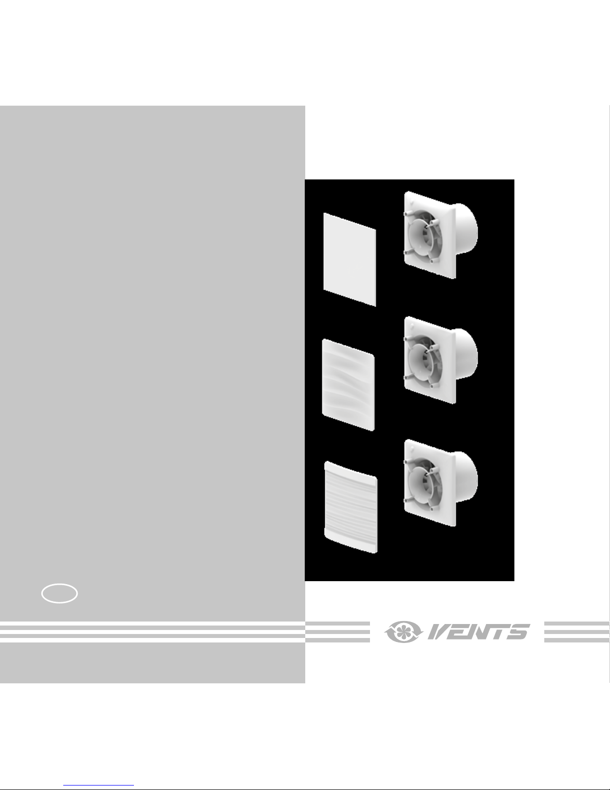
AXIAL FAN
User’s manual
www.ventilation-system.com
VENTS 100 Solid
VENTS 100 Wave
VENTS 100 Flip
EN
Page 2

2
EN
CONTENTS
Delivery set ............................................................................................................................................................................................................................................ 6
Brief description ................................................................................................................................................................................................................................. 6
Operation guidelines ....................................................................................................................................................................................................................... 6
Designation key ................................................................................................................................................................................................................................. 7
Mounting ................................................................................................................................................................................................................................................. 7
Electronic system operation algorithm ............................................................................................................................................................................... 7
Maintenance.......................................................................................................................................................................................................................................... 9
Storage and transportation regulations ............................................................................................................................................................................... 9
Manufacturer’s warranty ................................................................................................................................................................................................................ 10
Page 3
3
EN
This user’s manual is the primary operating document intended for technical, maintenance and operations staff.
The manual contains information about purpose, technical details, operating principle, design, and installation of the
VENTS 100 Solid (Wave/Flip) unit and all its modifications. Technical and maintenance staff must have proper theoretical
knowledge and practical training specific to ventilation systems as well as the necessary skills to carry out the work in
accordance with labour safety and construction regulations and standards applicable in the respective territory.
The information provided in the present document is true as at the document preparation. Due to the continuous product
development the company reserves the right to update the technical specifications, design or delivery package of its
products.
No part of the present publication may be reproduced, uploaded or saved in reference-providing information systems or
translated into other languages in any form whatsoever without the Company’s prior written consent.
READ THE USER’S MANUAL CAREFULLY BEFORE PROCEEDING WITH INSTALLATION WORKS.
COMPLIANCE WITH THE MANUAL REQUIREMENTS ENSURES RELIABLE OPERATION AND LONG
SERVICE LIFE OF THE UNIT.
KEEP THE USER’S MANUAL AVAILABLE AS LONG AS YOU USE THE UNIT. YOU MAY NEED TO RE-
READ THE INFORMATION ON THE PRODUCT SERVICING.
Page 4
4
EN
FOLLOW THE USER’S MANUAL REQUIREMENTS TO ENSURE DURABLE AND
TROUBLE-FREE OPERATION OF THE UNIT.
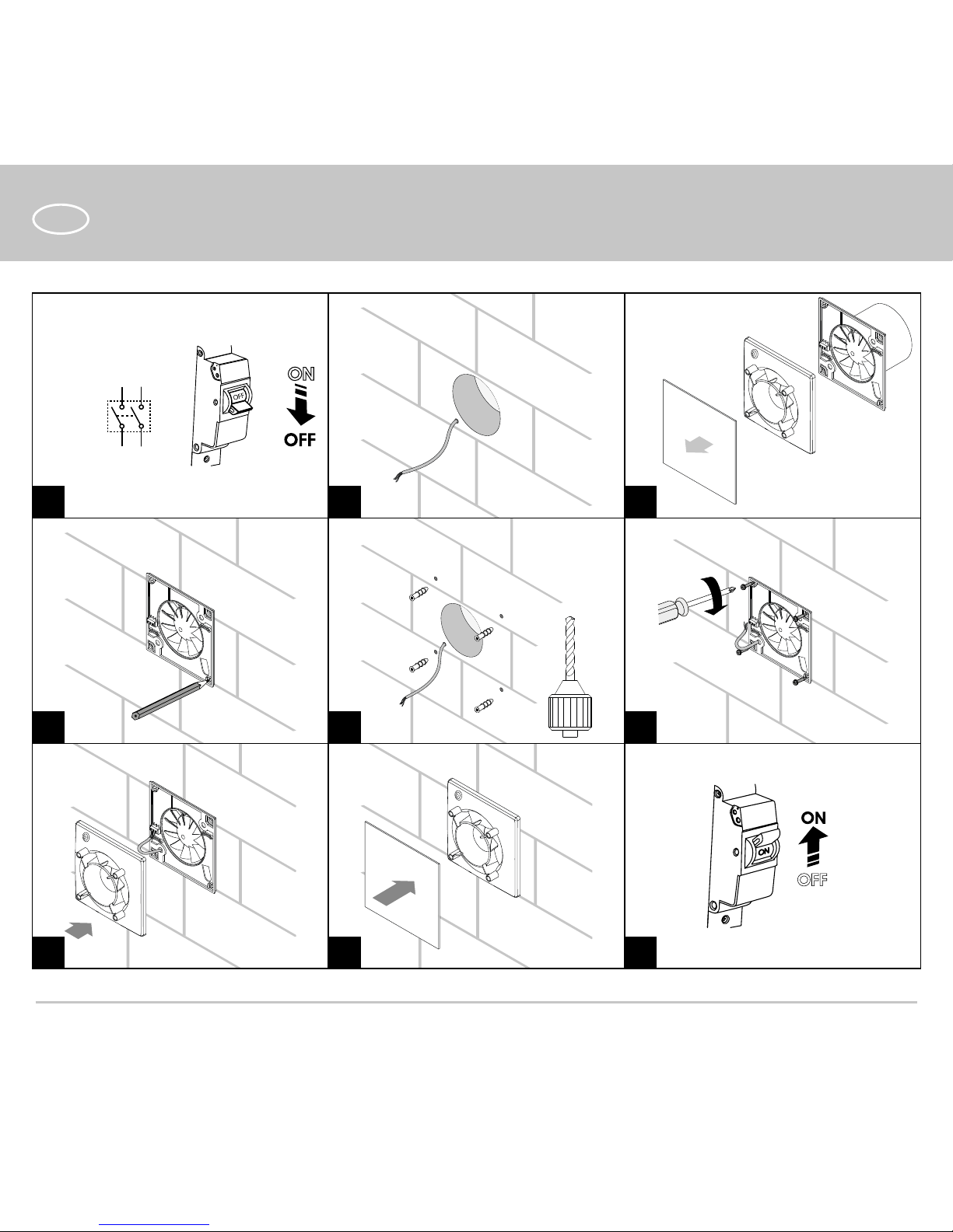
Disconnect the unit from power supply prior to any connection, servicing, maintenance, and repair
operations.
Only qualied electricians with a work permit for electrical units up to 1000 V are allowed
for installation and maintenance. The present user’s manual should be carefully read
before beginning works.
• Single-phase power mains must comply with the acting local electrical norms and standards.
• Fixed electrical wiring must be equipped with an automatic circuit breaker.
• The unit must be connected to power mains through a QF automatic circuit breaker
integrated into the fixed wiring system. The gap between the circuit breaker contacts on all
poles must be not less than 3 mm. Check the unit for any visible damages of the impeller and
the casing before starting installation. The casing internals must be free of any foreign objects
that can damage the impeller blades.
• While mounting the unit, avoid compression of the casing! Deformation of the casing
may result in the motor jam and noisy operation. Misuse of the unit and any unauthorised
modifications are not allowed.
• Take steps to prevent ingress of smoke, carbon monoxide, and other combustion products
into the room through open chimney flues or other fire-protection devices. Sufficient air
supply must be provided for proper combustion and exhaust of gases through the chimney of
fuel burning equipment to prevent back drafting. Transported air must not contain any dust or
Page 5
5
EN
THE PRODUCT MUST BE DISPOSED SEPARATELY AT THE END OF ITS SERVICE LIFE.
DO NOT DISPOSE THE UNIT AS UNSORTED MUNICIPAL WASTE.
other solid impurities, sticky substances, or fibrous materials.
• Do not use the unit in a hazardous or explosive environment containing spirits, gasoline,
insecticides, etc.
• Do not close or block the intake or extract vents in order to ensure the efficient air flow.
• Do not sit on the unit and do not put objects on it.
• The unit is allowed to be used by children aged from 8 years old and above and persons with
reduced physical, sensory, or mental capabilities or no experience and knowledge provided
that they have been given supervision or instruction regarding safe use of the unit and
understand the risks involved.
• Do not allow children to play with the unit.
Page 6

6
EN
DELIVERY SET
Fan - 1 item
Screws with dowels - 4 items
Plastic screwdriver - 1 item (only for the models with a timer)
User’s manual - 1 item
Packing box - 1 item
BRIEF DESCRIPTION
The product is an axial fan for exhaust ventilation of small and medium-sized premises heated in winter. The design of the fan
may include a back valve that prevents air from flowing into the room when the fan is off. The fan is designed for connection
to ø100 mm air ducts.
OPERATION GUIDELINES
The fan is rated for connection to 220...240 V / 50 Hz or 220...240 V / 60 Hz or 12 V / 50 Hz single-phase AC power mains,
depending on the model type. For more detailed information, see the casing sticker. Ingress protection rating against access to
hazardous parts and water ingress is IP44. The manufacturer’s recommended operating temperature range is +1 °C to + 45 °C.
The fan requires no grounding.
Page 7
7
EN
MOUNTING
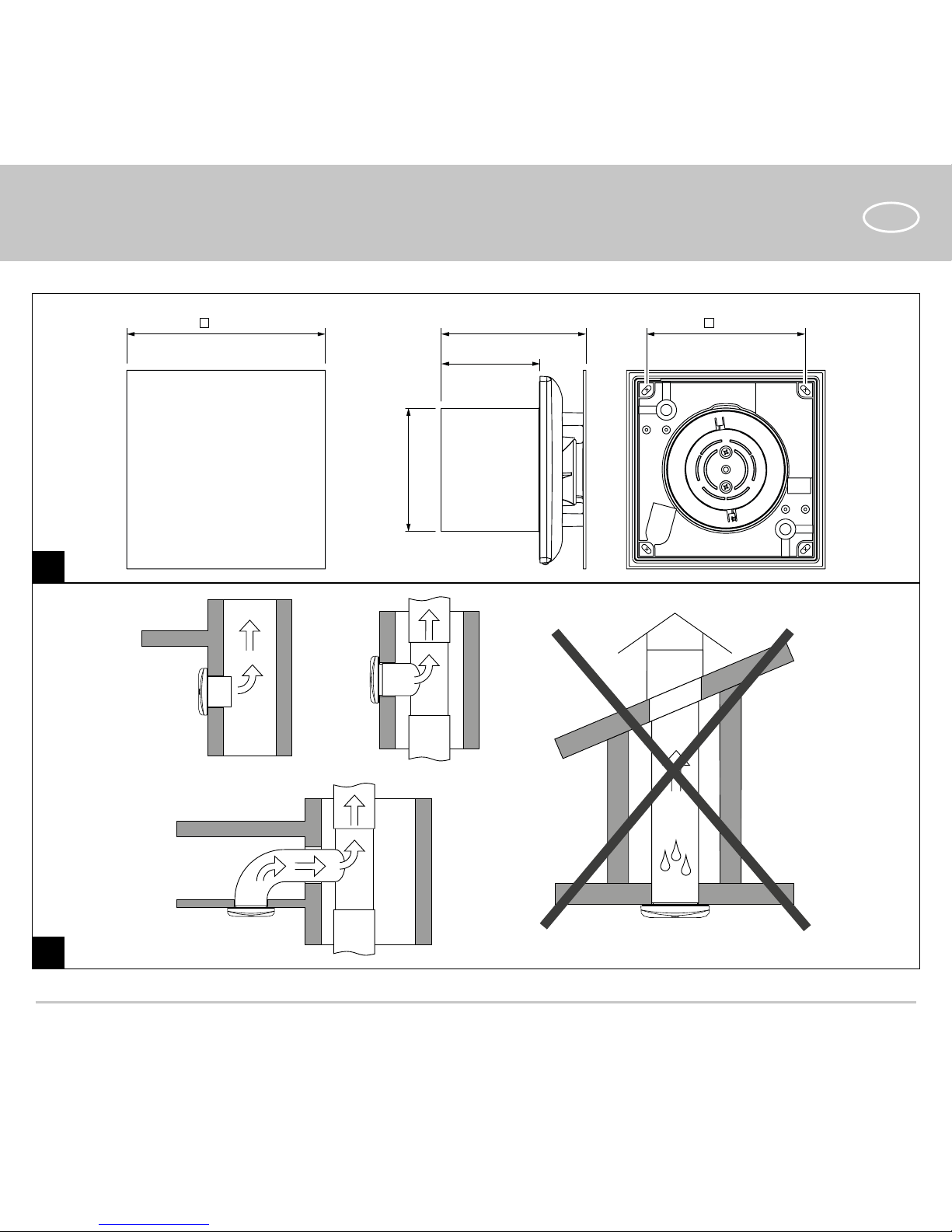
The fan can be mounted to the ceiling or onto a wall with air extraction into a ventilation shaft or a matching diameter
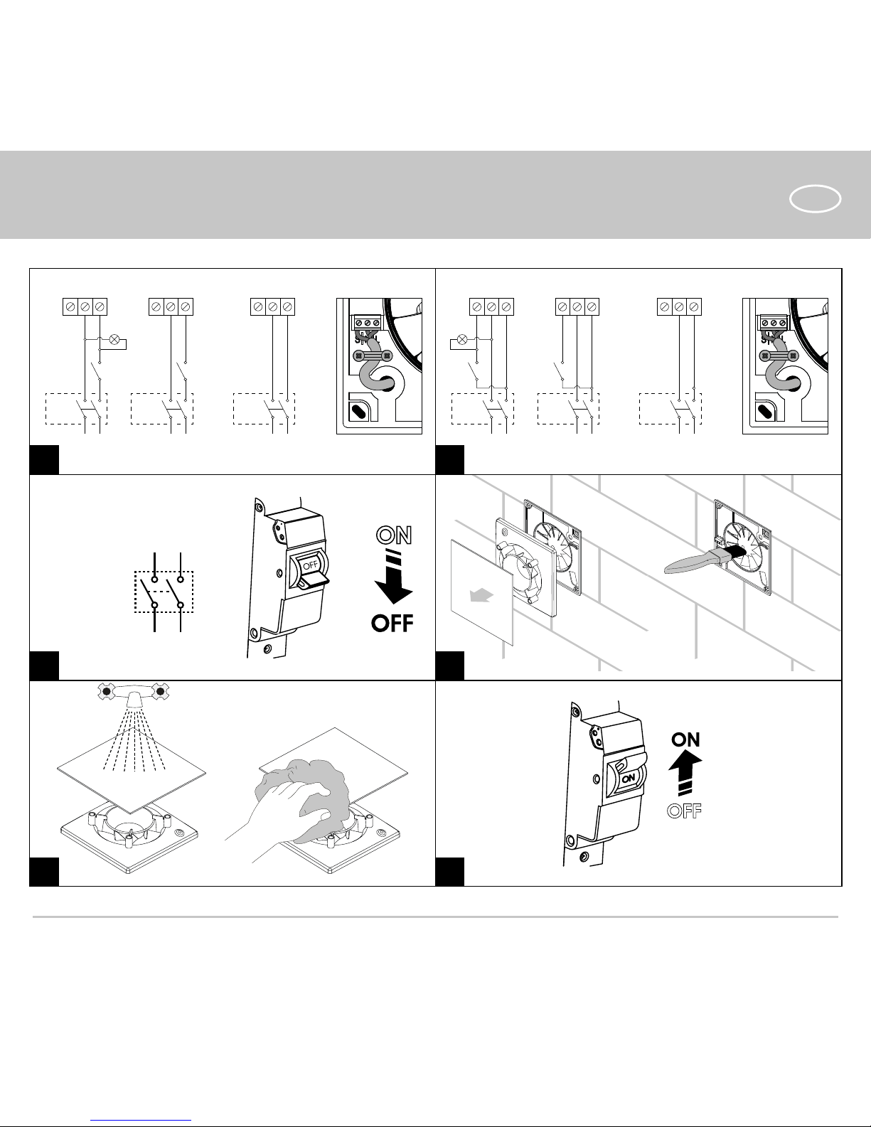
round air duct (Fig. 2). The fan installation steps are given on Fig. 3-11. Electric connection diagrams are given on Fig. 12-13.
Connection diagram terminal key:
L — phase (220-240 V only) SW — external switch
N — neutral (220-240 V only) QF — automatic switch.
S — timer control line
WARNING! Fans rated for 12 V (as specied on the fan packing and casing) must be connected to ~12 V electric
mains only!
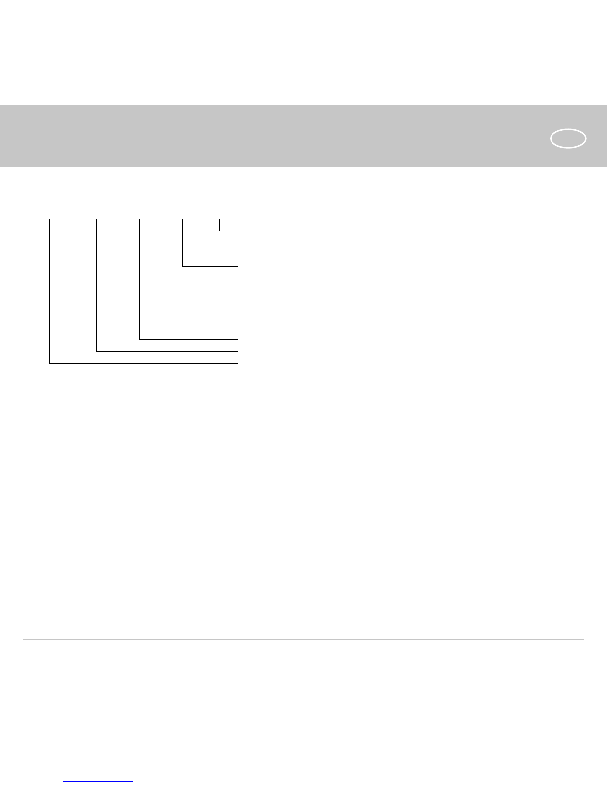
DESIGNATION KEY
VENTS 100 Solid X X
Motor modications
_ — basic motor
L — motor with ball bearings
Options
_ — basic model
S — cord-operated switch
Т — deactivation delay timer
Т1 — deactivation and activation delay timer
ТН — humidity sensor and deactivation delay timer
Fan series
Outlet duct diameter [mm]
Trade mark
ELECTRONIC SYSTEM OPERATION ALGORITHM
The T model fans equipped with a timer are activated by control voltage application to input terminal S by an external
switch (e.g. indoor light switch). Upon control voltage removal the fan continues to operate for the period of time set by the
timer within the range from 2 to 30 minutes. The ST model fans are activated and deactivated by the internal cord switch.
In T1 model fans equipped with a timer the activation delay timer is activated upon application of control voltage to input
terminal S by and an external switch (e.g. indoor light switch), but the fan blades remain in the stationary position. The
Page 8
8
EN
THE TIMER CIRCUIT IS LIVE.
MAKE SURE THE FAN IS DISCONNECTED FROM POWER SUPPLY.
activation delay value can be set in two ranges: from 10 to 90 seconds and from 2 minutes to 30 minutes. The adjustment
range can be selected by means of the jumper on the timer circuit board. Upon control voltage removal the fan continues
to operate for the period of time set by the timer within the range from 2 to 30 minutes.
The TH model fans equipped with a timer and a humidity sensor are activated by control voltage application to input
terminal S or on exceeding the pre-set humidity level H adjustable within the ~60 % to ~90 % range. Upon control voltage
removal or a decrease of humidity level H the fan continues to operate for the period of time set by the timer within the
range from 2 to 30 minutes. To adjust the maximum humidity level set the potentiometer knob to the Н mах (90 %) position.
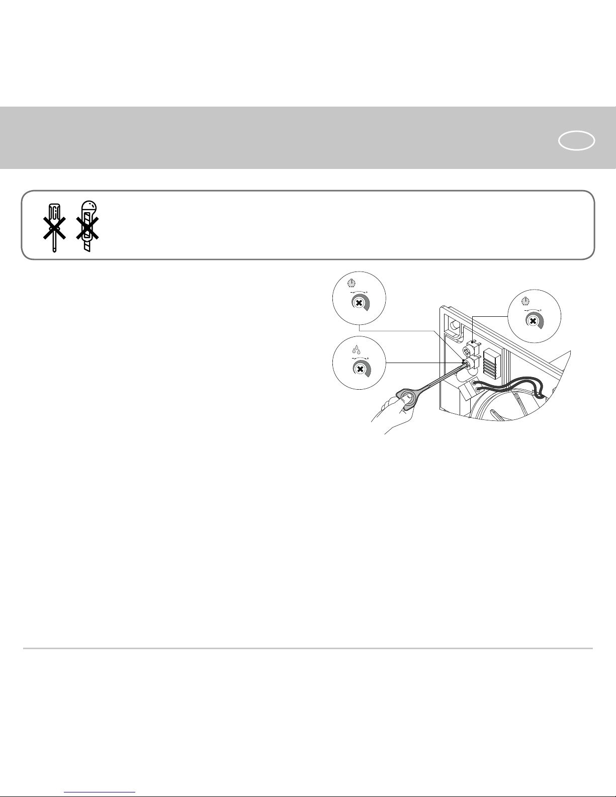
To adjust the fan activation delay time turn the Tz potentiometer knob clockwise (+) or counter-clockwise (-).
To adjust the fan deactivation delay time turn the T potentiometer knob clockwise (+) or counter-clockwise (-).
To adjust the threshold value of the humidity sensor turn the H potentiometer knob clockwise (+) or counter-clockwise (-).
— To adjust the fan activation delay time turn the Ton potentiometer knob clockwise (+) or counter-clockwise (-)
which sets the activation delay time within the range from 0 to 2 minutes.
— To adjust the fan deactivation delay time turn the To potentiometer knob clockwise (+) or counter-clockwise (-)
which sets the activation delay time within the range from 2 to 30 minutes.
— To adjust the humidity sensor threshold value turn the H potentiometer knob clockwise (+) or counter-clockwise (-)
which sets the threshold value within the range from 60 % to 90 %.
Page 9
9
EN
H
60%
90%
T
o
2 min
30 min
T
on
0 min
2 min
for Т1
for ТH/SТН
DO NOT USE A METAL SCREWDRIVER, KNIFE, ETC. FOR ADJUSTMENT
OPERATIONS NOT TO DAMAGE THE CIRCUIT BOARD.
MAINTENANCE
To clean the unit from any dust and dirt which may accumulate on the surfaces (Fig. 14-17) use a soft cloth and a brush
soaked in a mild detergent solution. Avoid spilling liquid on the electrical components. Wipe the cleaned surfaces dry.
• Store the unit in the manufacturer’s original packaging box in a dry closed ventilated premise with temperature range
from +5 ˚С to +40 ˚С .
• Storage environment must not contain aggressive vapours and chemical mixtures provoking corrosion, insulation, and
sealing deformation.
• Use suitable hoist machinery for handling and storage operations to prevent possible damage to the unit.
• Follow the handling requirements applicable for the particular type of cargo.
• The unit can be carried in the original packaging by any mode of transport provided proper protection against
precipitation and mechanical damage. The unit can be transported only in the working position.
STORAGE AND TRANSPORTATION REGULATIONS
The fan is supplied with a special plastic screwdriver. Use the
screwdriver to adjust the fan activation or deactivation delay
or the humidity sensor threshold value.
Page 10

10
EN
• Avoid sharp blows, scratches, or rough handling during loading and unloading.
• Prior to the initial power-up after transportation at low temperatures allow the unit to warm up at room temperature
for at least 3-4 hours.
The product is in compliance with EU norms and standards on low voltage guidelines and electromagnetic compatibility.
We hereby declare that the product complies with the provisions of Electromagnetic Council Directive 2014/30/EU, Low
Voltage Directive 2014/35/EU and CE-marking Directive 93/68/EEC. This certificate is issued following test carried out on
samples of the product referred to above.
The manufacturer hereby warrants normal operation of the unit for 60 months after the retail sale date provided the user's
observance of the transportation, storage, installation, and operation regulations.
Should any malfunctions occur in the course of the unit operation through the Manufacturer's fault during the guaranteed
period of operation, the user is entitled to get all the faults eliminated by the manufacturer by means of warranty repair at
the factory free of charge. The warranty repair includes work specific to elimination of faults in the unit operation to ensure
its intended use by the user within the guaranteed period of operation.
The faults are eliminated by means of replacement or repair of the unit components or a specific part of such unit component.
The warranty repair does not include:
• routine technical maintenance
• unit installation/dismantling
• unit setup
To benefit from warranty repair, the user must provide the unit, the user's manual with the purchase date stamp, and the
payment paperwork certifying the purchase.
The unit model must comply with the one stated in the user’s manual.
Contact the Seller for warranty service.
The manufacturer’s warranty does not apply to the following cases:
• User’s failure to submit the unit with the entire delivery package as stated in the user’s manual including submission
with missing component parts previously dismounted by the user.
• Mismatch of the unit model and the brand name with the information stated on the unit packaging and in the user's
manual.
• User’s failure to ensure timely technical maintenance of the unit.
MANUFACTURER’S WARRANTY
Page 11
11
EN
• External damage to the unit casing (excluding external modifications as required for installation) and internal
components caused by the user.
• Redesign or engineering changes to the unit.
• Replacement and use of any assemblies, parts and components not approved by the manufacturer.
• Unit misuse.
• Violation of the unit installation regulations by the user.
• Violation of the unit control regulations by the user.
• Unit connection to power mains with a voltage different from the one stated in the user's manual.
• Unit breakdown due to voltage surges in power mains.
• Discretionary repair of the unit by the user.
• Unit repair by any persons without the manufacturer’s authorization.
• Expiration of the unit warranty period.
• Violation of the unit transportation regulations by the user.
• Violation of the unit storage regulations by the user.
• Wrongful actions against the unit committed by third parties.
• Unit breakdown due to circumstances of insuperable force (fire, flood, earthquake, war, hostilities of any kind,
blockades).
• Missing seals if provided by the user’s manual.
• Failure to submit the user’s manual with the unit purchase date stamp.
• Missing payment paperwork certifying the unit purchase.
FOLLOWING THE REGULATIONS STIPULATED HEREIN WILL ENSURE A LONG AND TROUBLE-FREE
OPERATION OF THE UNIT.
USERS’ WARRANTY CLAIMS SHALL BE SUBJECT TO REVIEW ONLY UPON PRESENTATION OF THE
UNIT, THE PAYMENT DOCUMENT AND THE USER’S MANUAL WITH THE PURCHASE DATE STAMP.
Page 12
12
EN
160 128117
79
ø 99
1.
2.
Page 13
13
EN
QF
L N
3. 4. 5.
6. 7. 8.
9. 10. 11.
Page 14
14
EN
S NQFL
N L
S
S NQFL
N L
S
S
- V
NQFL
N L
QF
L N
S N
S
QF
L
N L
S N
S
QF
L
N L
NQFL
N L
Т/TH VТ/VTH
12.
14.
16.
13.
15.
17.
Page 15

15
EN
Quality Inspector’s Stamp
Manufacture Date
Seller
(name and stamp of the seller)
Purchase Date
Page 16

V160EN-02
Acceptance certificate
The fan is recognized as serviceable.
We hereby declare that the product complies
with the essential protection requirements of
Electromagnetic Council Directive 2004/108/EC,
89/336/EEC and Low Voltage Directive 2006/95/EC,
73/23/EEC and CE-marking Directive 93/68/EEC on
the approximation of the laws of the Member States
relating to electromagnetic compatibility.
This certificate is issued following test carried out on
samples of the product referred to above.
 Loading...