

Page 1
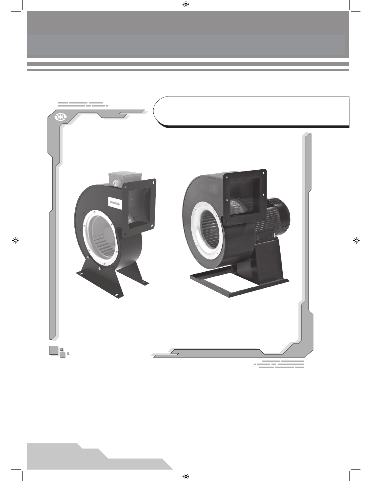
USER’S MANUAL
VCU/VCUN Series
CENTRIFUGAL FAN IN
SCROLL CASING
V16EN-07.indd 1 03.11.2015 14:24:55
Page 2

2
CONTENTS
Introduction
Use
Delivery set
Designation key
Technical data
Safety requirements
Design and operating logic
Mounting and set-up
Connection to power mains
Maintenance
Troubleshooting
Storage and transportation rules
Manufacturer’s warranty
Acceptance certicate
Connection certicate
Warranty card
3
3
3
3
4
10
10
11
12
15
17
17
17
18
18
18
V16EN-07.indd 2 03.11.2015 14:24:55
Page 3
3
VCU/VCUN
INTRODUCTION
USE
DELIVERY SET
This user’s manual includes technical description, operation, installation and mounting guidelines, technical data for VCU centrifugal
fan in metal spiral casing with an integrated motor and the impeller diameter from 140 up to 250 mm as well as VCUN centrifugal fan in a
metal spiral casing with an external motor and the impeller diameter from 140 up to 500 mm, hereinafter the fan.
Fan - 1 item;
User’s manual - 1 item;
Fixing bracket (for VCU fans) - 1 item;
Packing box - 1 item.
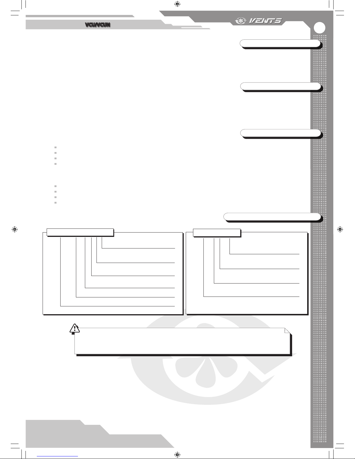
DESIGNATION KEY
The centrifugal inline fans are designed for supply and extract ventilation of residential, public and industrial premises.
The fan is rated for continuous operation always connected to power mains.
Transported air must not contain any ammable or explosive mixtures, evaporation of chemicals, coarse dust, soot and oil particles,
sticky substances, brous materials, pathogens or any other harmful substances.
Power mains parameters
Name of the device
VCU - centrifugal fan with an integrated motor
VCU Х Х ХхХ
Impeller dimensions [mm]
E - single-phase
Number of poles
2, 4, 6
Motor power [kW]
Name of the device
VCUN - centrifugal fan with an external motor
VCUN ХхХ-Х-Х-Х-Х
Impeller dimensions [mm]
Number of poles
2; 4; 6; 8
Version
R - Right-handed, L - left-handed
Scroll positioning
0; 45; 90; 135; 180; 225; 270; 315
THE STANDARD VCUN MODEL HAS 90° CASING ANGLE AND A RIGHT-HANDED IMPELLER ROTATION.
THE FAN CASING ROTATION ANGLE MODIFICATIONS ARE SHOWN IN FIG. 2, PAGE 7.
Fan accessories:
Air intake grille RVC-VCU, RVC-VCUN;
Air intake ange FVC-VCU, FVC-VCUN;
VVCr - rubber anti-vibration mounts;
VVCp - spring-loaded anti-vibration mounts;
V16EN-07.indd 3 03.11.2015 14:24:56
Page 4
4
The fan is designed for indoor application with the ambient temperature ranging from 0°C up to +45°C and relative humidity up to
80%.
The fan design is regularly improved, so some models may slightly dier from those ones described in this manual.
Ingress Protection (IP) rating from solid objects and liquids is IP X4 for the VCU models and IP54 for the VCUN fans.
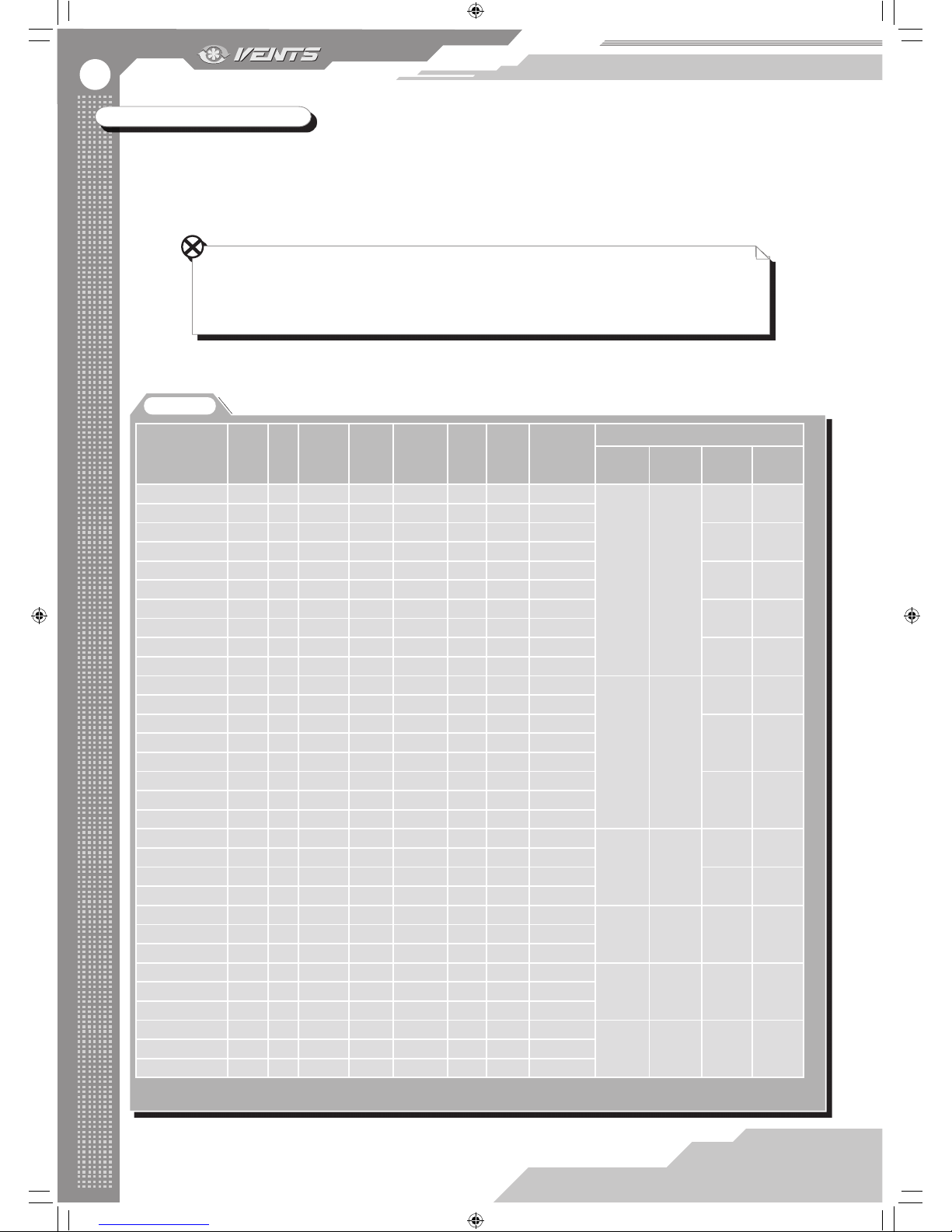
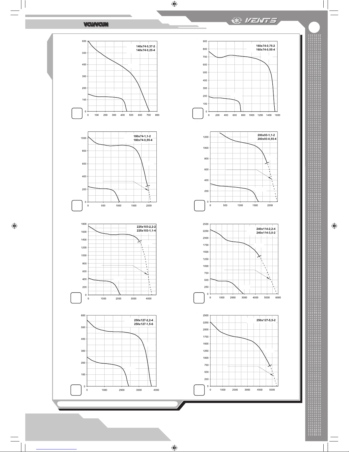
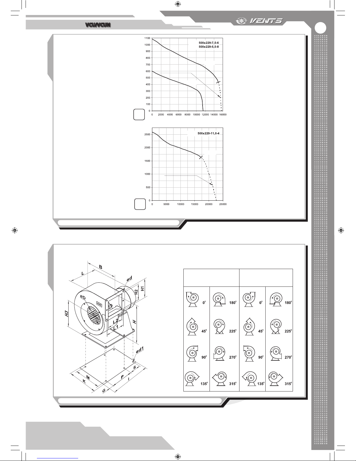
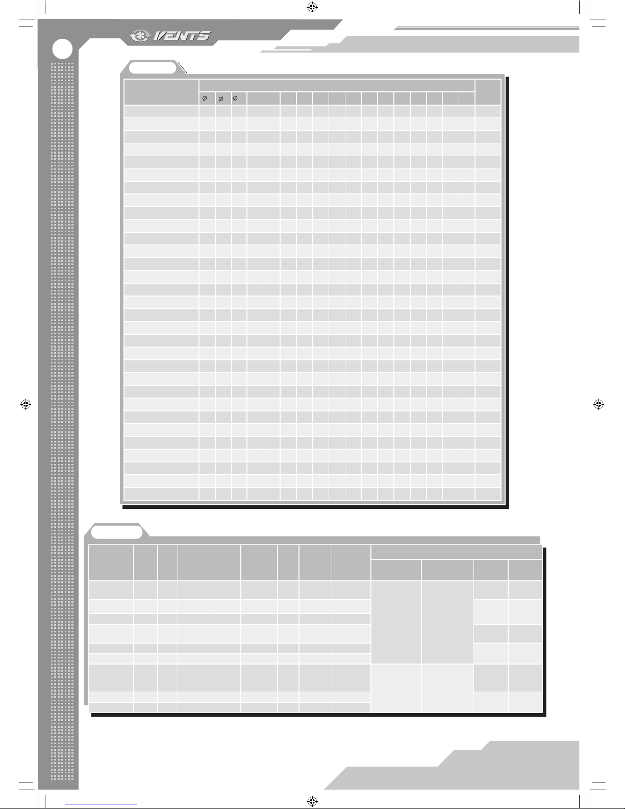
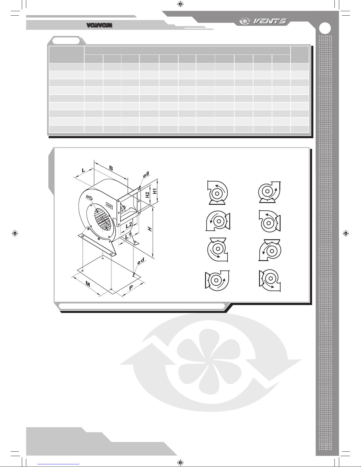
The main overall and connection dimensions, outer view and technical data are shown in g. 1 and in table 1, 2, 3, 4.
TECHNICAL DATA
DURING THE FAN OPERATION AND THE TRIAL RUN OF THE UNCONNECTED FAN THE AIR FLOW AND
THE CURRENT CONSUMPTION MUST NOT EXCEED THE MAXIMUM ALLOWABLE VALUES FOR THE
APPLICABLE FAN SIZE, SEE THE HIGHLIGHTED AREAS IN TABLES 1, 3 AND FIG. 1.1-1.19. THE MOTOR
HEAT PROTECTION MUST BE PROVIDED!
Table 1
Fan model
Supply
Voltage, 50
Hz [V]
Power
[kW]
Current
consumption
[A]
Circuit
breaker trip
current [A]
Max. air
capacity [m3/h]
RPM
[min
-1
]
Noise level,
3 m [dBA]
Max. transported
air temperature
[°C]
Compatibility of accessories
Rubber
anti-vibration
mounts
Spring-loaded
anti-vibration
mounts
Flange
Grille
VCUN 140х74-0,25-4 400 0,25 0,8 1,6 450 1350 60 60
VVCr 8 VVCp 8
FVC-VCUN
140
RVC-VCUN
140
VCUN 140х74-0,37-2 400 0,37 0,9 1,6 710 2730 65 60
VCUN 160х74-0,55-4 400 0,55 1,6 2,5 750 1360 62 60
FVC-VCUN
160
RVC-VCUN
160
VCUN 160х74-0,75-2 400 0,75 1,8 2,5 1540 2820 68 60
VCUN 180х74-0,55-4 400 0,55 1,6 2,5 1030 1360 64 60
FVC-VCUN
180
RVC-VCUN
180
VCUN 180х74-1,1-2 400 1,1 2,6 3,2 1950 2800 70 60
VCUN 200х93-0,55-4 400 0,55 1,6 2,5 1615 1360 67 60
FVC-VCUN
200
RVC-VCUN
200
VCUN 200х93-1,1-2 400 1,1 2,6 3,2 1900 2800 73 60
VCUN 225х103-1,1-4 400 1,1 2,8 3,2 2125 1420 72 60
FVC-VCUN
225
RVC-VCUN
225
VCUN 225х103-2,2-2 400 2,2 4,7 6,3 3350 2865 75 60
VCUN 240х114-2,2-4 400 2,2 5,1 6,3 2930 1420 74 60
VVCr 16 VVCp 16
FVC-VCUN
240
RVC-VCUN
240
VCUN 240х114-3,0-2 400 3,0 6,1 8,0 4350 2870 78 60
VCUN 250х127-1,5-6 400 1,5 4,2 6,3 2415 940 68 60
FVC-VCUN
250
RVC-VCUN
250
VCUN 250х127-2,2-4 400 2,2 5,1 6,3 3720 1420 78 60
VCUN 250х127-5,5-2 400 5,5 10,7 12,5 4820 2850 81 60
VCUN 280х127-1,5-6 400 1,5 4,2 6,3 3450 940 69 60
FVC-VCUN
280
RVC-VCUN
280
VCUN 280х127-2,2-4 400 2,2 5,1 6,3 4395 1420 75 60
VCUN 280х127-5,5-2 400 5,5 10,7 12,5 6330 2850 81 60
VCUN 315х143-2,2-6 400 2,2 5,6 6,3 4375 940 70 60
VVCr 26 VVCp 26
FVC-VCUN
315
RVC-VCUN
315
VCUN 315х143-4,0-4 400 4,0 8,7 10,0 6530 1410 79 60
VCUN 355х143-2,2-6 400 2,2 5,6 6,3 5090 940 71 60
FVC-VCUN
355
RVC-VCUN
355
VCUN 355х143-4,0-4 400 4,0 8,7 10,0 8150 1410 79 60
VCUN 400х183-1,5-8 400 1,5 4,2 6,3 6545 700 62 60
VVCr 35 VVCp 35
FVC-VCUN
400
RVC-VCUN
400
VCUN 400х183-2,2-6 400 2,2 5,8 6,3 8100 940 73 60
VCUN 400х183-5,5-4 400 5,5 11,0 16,0 10175 1430 80 60
VCUN 450х203-3,0-8 400 3,0 7,8 10,0 10230 700 70 60
VVCr 50 VVCp 50
FVC-VCUN
450
RVC-VCUN
450
VCUN 450х203-4,0-6 400 4,0 9,1 12,5 11150 950 76 60
VCUN 450х203-11,0-4 400 11,0 24,0 31,5 19000 1450 84 60
VCUN 500х229-5,5-8 400 5,5 14,8 16,0 11550 700 72 60
VVCr 75 VVCp 75
FVC-VCUN
500
RVC-VCUN
500
VCUN 500х229-7,5-6 400 7,5 17,0 20,0 14960 955 78 60
VCUN 500х229-11,0-4 400 11,0 24,0 31,5 17250 1450 85 60
Allowable deviation of power mains voltage is ±10% of the rated voltage.
V16EN-07.indd 4 03.11.2015 14:24:57
Page 5
5
VCU/VCUN
1 2
3 4
5 6
7 8
Pressure ΔP [Pa]
Air capacity [m3/h]
Pressure ΔP [Pa]
Air capacity [m3/h]
Pressure ΔP [Pa]
Air capacity [m3/h]
Pressure ΔP [Pa]
Air capacity [m3/h]
Pressure ΔP [Pa]
Air capacity [m3/h]
Pressure ΔP [Pa]
Air capacity [m3/h]
Pressure ΔP [Pa]
Air capacity [m3/h]
Pressure ΔP [Pa]
Air capacity [m3/h]
0.37 kW
0.75 kW
0.55 kW
1.1 kW
0.55 kW
VCUN
VCUN
VCUN
VCUN
VCUN
VCUN
VCUN
VCUN
VCUN
VCUN
VCUN
VCUN VCUN
VCUN
Do not operate in this
operating area
Do not operate in this
operating area
Do not operate in this
operating area
Do not operate in this
operating area
Do not operate in this
operating area
VCUN
0.25 kW
1.1 kW
2.2 kW
2.2 kW
3.0 kW
2.2 kW
5.5 kW
1.5 kW
1.1 kW
0.55 kW
Fig. 1. Aerodynamic fan characteristics
V16EN-07.indd 5 03.11.2015 14:24:58
Page 6
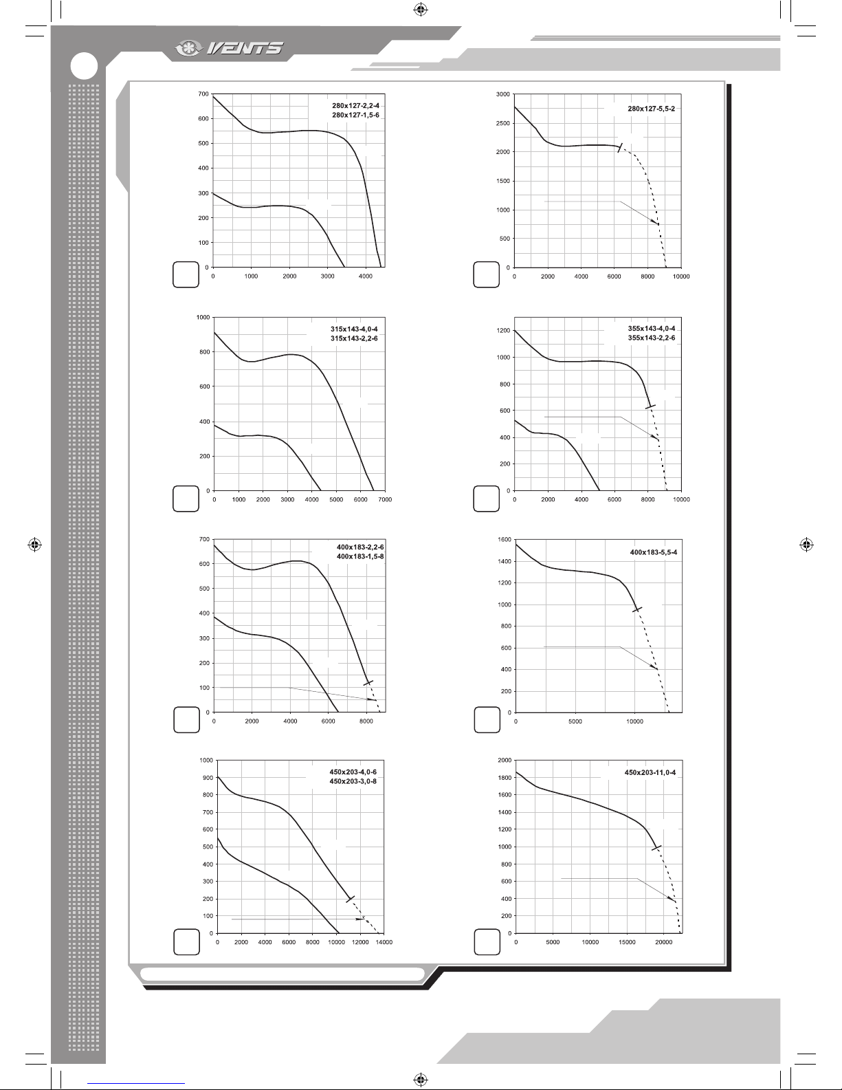
6
7 8
9 10
11 12
13 14
15
16
Pressure ΔP [Pa]
Air capacity [m3/h]
Pressure ΔP [Pa]
Air capacity [m3/h]
Pressure ΔP [Pa]
Air capacity [m3/h]
Pressure ΔP [Pa]
Air capacity [m3/h]
Pressure ΔP [Pa]
Air capacity [m3/h]
Pressure ΔP [Pa]
Air capacity [m3/h]
Pressure ΔP [Pa]
Air capacity [m3/h]
Pressure ΔP [Pa]
Air capacity [m3/h]
Pressure ΔP [Pa]
Air capacity [m3/h]
Pressure ΔP [Pa]
Air capacity [m3/h]
VCUN VCUN
VCUN
VCUN
VCUN
VCUN
VCUN
VCUN
VCUN
VCUN
VCUN
VCUN
VCUN
VCUN
Do not operate in this
operating area
Do not operate in this
operating area
Do not operate in this
operating area
Do not operate in this
operating area
Do not operate in this
operating area
Do not operate in this
operating area
Do not operate in this
operating area
2.2 kW
5.5 kW
5.5 kW
2.2 kW
4.0 kW
2.2 kW
1.5 kW
4.0 kW
3.0 kW
11.0 kW
2.2 kW
VCUN
VCUN
4.0 kW
5.5 kW
1.5 kW
1.5 kW
Fig. 1. Aerodynamic fan characteristics
V16EN-07.indd 6 03.11.2015 14:25:00
Page 7
7
VCU/VCUN
9 10
11 12
13 14
15
16
17
18
Pressure ΔP [Pa]
Air capacity [m3/h]
Pressure ΔP [Pa]
Air capacity [m3/h]
Pressure ΔP [Pa]
Air capacity [m3/h]
Pressure ΔP [Pa]
Air capacity [m3/h]
Pressure ΔP [Pa]
Air capacity [m3/h]
Pressure ΔP [Pa]
Air capacity [m3/h]
Pressure ΔP [Pa]
Air capacity [m3/h]
Pressure ΔP [Pa]
Air capacity [m3/h]
Pressure ΔP [Pa]
Air capacity [m3/h]
Pressure ΔP [Pa]
Air capacity [m3/h]
VCUN
VCUN
VCUN
VCUN
VCUN
VCUN
VCUN
VCUN
VCUN
VCUN
VCUN
VCUN
VCUN
VCUN
Do not operate in this
operating area
Do not operate in this
operating area
Do not operate in this
operating area
Do not operate in this
operating area
Do not operate in this
operating area
Do not operate in this
operating area
Do not operate in this
operating area
Do not operate in this
operating area
5.5 kW
2.2 kW
4.0 kW
2.2 kW
1.5 kW
4.0 kW
3.0 kW
7.5 kW 11.0 kW
5.5 kW
11.0 kW
2.2 kW
VCUN
VCUN
4.0 kW
5.5 kW
1.5 kW
16
18
Pressure ΔP [Pa]
Air capacity [m3/h]
Pressure ΔP [Pa]
Air capacity [m3/h]
Pressure ΔP [Pa]
Air capacity [m3/h]
Pressure ΔP [Pa]
Air capacity [m3/h]
Pressure ΔP [Pa]
Air capacity [m3/h]
VCUN
VCUN
VCUN
VCUN
Do not operate in this
operating area
Do not operate in this
operating area
Do not operate in this
operating area
Do not operate in this
operating area
Do not operate in this
operating area
5.5 kW
11.0 kW
VCUN
VCUN
4.0 kW
5.5 kW
Fig. 1. Aerodynamic fan characteristics
Fig. 2. VCUN fan overall dimensions and casing rotation options
Possible VCUN casing rotation options
(view on intake side)
Impeller right-handed
rotation
Impeller left-handed
rotation
R R L L
R R L L
R R L L
R R L L
V16EN-07.indd 7 03.11.2015 14:25:01
Page 8
8
Table 2
Fan type
Dimensions [mm]
Weight
[kg]
D
d
d1 B H H1 H2 H3 L L1 L2 P M l G K S
VCUN 140х74-0,25-4 140 8 10 242 323 125 92 144 309 125 95 124 220 234 18 253 80 9,3
VCUN 140х74-0,37-2
140 8 10 242 323 125 92 144 309 125 95 124 220 234 18 253 80 9,3
VCUN 160х74-0,55-4
160 8 10 277 373 134 106 173 356 134 104 141 220 260 17 252 90 12,7
VCUN 160х74-0,75-2
160 8 10 277 373 134 106 173 356 134 104 141 220 260 17 252 90 13,0
VCUN 180х74-0,55-4
180 10 10 311 414 143 120 193 365 143 114 146 270 270 22 314 90 13,5
VCUN 180х74-1,1-2
180 10 10 311 414 143 120 193 365 143 114 146 270 270 22 314 90 14,5
VCUN 200х93-0,55-4
200 10 10 345 436 160 134 193 380 160 129 158 270 284 24 315 90 15,2
VCUN 200х93-1,1-2
200 10 10 345 436 160 134 193 380 160 129 158 270 284 24 315 90 16,2
VCUN 225х103-1,1-4
225 10 12 388 507 178 151 232 432 172 141 174 275 316 27 330 100 21,2
VCUN 225х103-2,2-2
225 10 12 388 507 178 151 232 432 172 141 174 275 316 27 330 100 24,2
VCUN 240х114-2,2-4
240 10 12 414 568 186 161 282 461 186 156 195 275 362 27 330 125 30,5
VCUN 240х114-3,0-2
240 10 12 414 568 186 161 282 461 186 156 195 275 362 27 330 125 31,4
VCUN 250х127-1,5-6
250 10 12 431 594 202 168 292 473 202 166 206 300 373 27 355 125 33,0
VCUN 250х127-2,2-4
250 10 12 431 594 202 168 292 473 202 166 206 300 373 27 355 125 32,2
VCUN 250х127-5,5-2
250 10 12 431 614 202 168 312 517 202 166 213 300 397 27 355 140 40,0
VCUN 280х127-1,5-6
280 10 12 483 626 225 189 292 503 231 196 243 300 410 27 355 125 35,1
VCUN 280х127-2,2-4
280 10 12 483 626 225 189 292 503 231 196 243 300 410 27 355 125 34,2
VCUN 280х127-5,5-2
280 10 12 483 646 225 189 312 545 231 196 243 300 427 27 355 140 42,4
VCUN 315х143-2,2-6
315 10 15 543 731 250 213 353 568 255 216 268 350 452 27 405 140 46,8
VCUN 315х143-4,0-4
315 10 15 543 731 250 213 353 568 255 216 268 350 452 27 405 140 49,8
VCUN 355х143-2,2-6
355 10 15 611 817 275 241 403 566 255 214 253 350 442 32 405 140 49,0
VCUN 355х143-4,0-4
355 10 15 611 817 275 241 403 566 255 214 253 350 442 32 405 140 51,0
VCUN 400х183-1,5-8
400 10 15 689 870 310 272 403 619 310 268 313 400 497 27 455 140 57,1
VCUN 400х183-2,2-6
400 10 15 689 870 310 272 403 619 310 268 313 400 497 27 455 140 54,1
VCUN 400х183-5,5-4
400 10 15 689 882 310 272 414 662 330 289 341 400 525 27 455 140 69,5
VCUN 450х203-3,0-8
450 10 15 774 985 345 306 464 690 352 315 351 450 550 42 530 140 77,8
VCUN 450х203-4,0-6
450 10 15 774 985 345 306 464 690 352 315 351 450 550 42 530 140 76,5
VCUN 450х203-11,0-4
450 10 15 774 1005 345 306 484 722 352 315 371 450 608 42 530 178 105,0
VCUN 500х229-5,5-8
500 11 15 860 1115 390 341 534 761 401 353 408 500 645 42 580 178 85,0
VCUN 500х229-7,5-6
500 11 15 860 1115 390 341 534 761 401 353 408 500 645 42 580 178 86,0
VCUN 500х229-11,0-4
500 11 15 860 1115 390 341 534 761 401 353 408 500 645 42 580 178 107,0
Table 3
Fan type
Supply
Voltage,
50 Hz
[V]
Power
[W]
Current
consumption
[A]
Circuit
breaker trip
current [A]
Max. air
capacity [m3/h]
RPM
[min-1]
Noise level, 3
m [dBA]
Max.
transported air
temperature
[°C]
Compatibility of accessories
Rubber anti-vibration
mounts
Spring-loaded
anti-vibration mounts
Flange Grille
VCU 2Е 140х60 230 148 0,64
1,6 515 2820
68 -25 +45
VVCr 8 VVCp 8
FVC-VCU
140
RVC-VCU
140
VCU 2Е 160х62 230 320
1,48 1,6 755 2630
70 -25 +50
FVC-VCU
160
RVC-VCU
160
VCU 2Е 160х90 230 320 1,48 2,5 730 2745 70 -25 +45
VCU 4Е 180х92 230 160
0,70 1,6 800
1465 62 -25 +45
FVC-VCU
180
RVC-VCU
180
VCU 4Е 200х80 230 125 0,55 1,6 730 1430 63 -25 +45
FVC-VCU
200
RVC-VCU
200
VCU 4Е 200х102 230 280 1,25 1,6 1350 1475 65 -25 +40
VCU 4Е 225х102 230 395 1,98 2,5 1480 1330 69 -40 +70
VVCr 16 VVCp 16
FVC-VCU
200 /FVCVCUN 225
RVC-VCU
200 / RVCVCUN 225
VCU 4Е 250х102 230 810 3,65 5,0 2000 1330 63 -40 +70
FVC-VCU
250
RVC-VCU
250
VCU 4Е 250х140 230 570 2,48 3,15 2000 1310 60 -40 +70
Allowable deviation of power mains voltage is ±10% of the rated voltage.
V16EN-07.indd 8 03.11.2015 14:25:03
Page 9
9
VCU/VCUN
Table 4
Fan type
Dimensions [mm]
Weight
[kg]
ØD
B
H
H1
H2
L
L1
L2
P
M
Ød
VCU 2Е 140х60 140
243
287 125
93 85
107
75 116
150 9
3,5
VCU 2Е 160х62 160
277
324
136
106
89
112
82
122
200
9
4,6
VCU 2Е 160х90 160
277
324 136
106 136
158
127 168
200 9
5,5
VCU 4Е 180х92
180
311
360
150
120
145
166
137
181
230
9
7,1
VCU 4Е 200х80
200 345 398 165 134 116 140 108 150 240 9 7,5
VCU 4Е 200х102
200 345 398 165 134 152 175 143 185 240 9 8,0
VCU 4Е 225х102
225 365 441 210 171 145 170 137 178 250 11 11,9
VCU 4Е 250х102 250 410 485 230 191 165 190 157 198 270 11 16,3
VCU 4Е 250х140 250 410 485 230 191 205 230 197 238 270 11 16,3
Fig. 3. VCU fan overall dimensions and casing rotation options
Possible VCU casing rotation options
(view on intake side)
V16EN-07.indd 9 03.11.2015 14:25:03
Page 10
10
DO NOT! THE FAN MUST NOT BE OPERATED OUTSIDE THE TEMPERATURE RANGE STATED IN THE
USER’S MANUAL OR IN AGGRESSIVE OR EXPLOSIVE ENVIRONMENTS.
WARNING!
DISCONNECT THE FAN FROM POWER MAINS PRIOR TO MAINTENANCE AND SERVICING OPERATIONS
AND MAKE SURE THAT THE IMPELLER HAS COME TO A FULL STOP.
SAFETY REQUIREMENTS
Installation and operation of the fan shall be performed in accordance with the present user’s manual as well as the provisions of all the
applicable local and national construction, electrical and technical codes and standards.
Mounting and electric connection of the fan are allowed only by duly qualied electricians in compliance with valid rated norms.
The fan must be grounded!
Check the fan for any visible damages of impeller and casing prior to connecting the fan to power mains. The fan casing must not contain
any foreign objects which can damage the impeller blades. Otherwise please contact the service centre.
Misuse of the fan or, any unauthorized design alteration or modications are not allowed.
The fan is classied as a class I electric appliance.
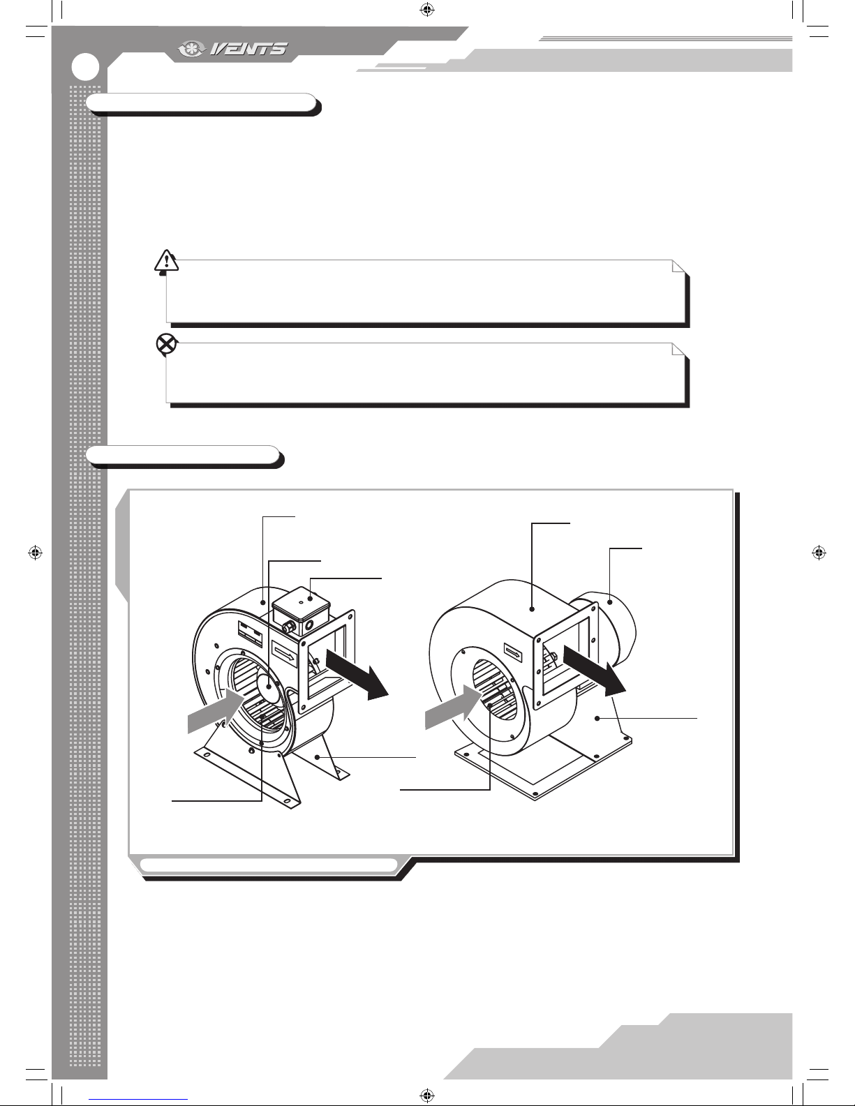
DESIGN AND OPERATING LOGIC
Fig. 4. Fan design and operating logic
Casing
Impeller
Motor
Fixing bracket
Casing
Fixing bracket
Motor
Terminal block
Impeller
VCU VCUN
The VCUN series fan consists of a metal casing connected to the motor and the intake ring through the ange, g. 4. The impeller is
xed to the drive shaft. The mounting bracket is xed on the bottom to the electric motor for mounting of the fan.
The VCUN fans are available in right-handed and left-handed modications. The impeller of the right-handed models has clockwise
rotation and the impeller of the left-handed models has counter-clockwise rotation, view on air intake side, g. 2.
The VCUN series fan consists of a metal casing with an impeller with an electric motor that is screwed to the ange. The terminal box
with the operating capacitor is xed on the casing top and is used for connection to power mains.
The xing brackets are used for the fan mounting.
V16EN-07.indd 10 03.11.2015 14:25:04
Page 11
11
VCU/VCUN
MOUNTING AND SET-UP
After the fan unpacking, prior to the mounting:
read carefully the user’s manual and the mounting, start-up, operating and servicing guidelines.
Check the fan for any transport damages.
Full the safety requirements during the fan set-up and operation.
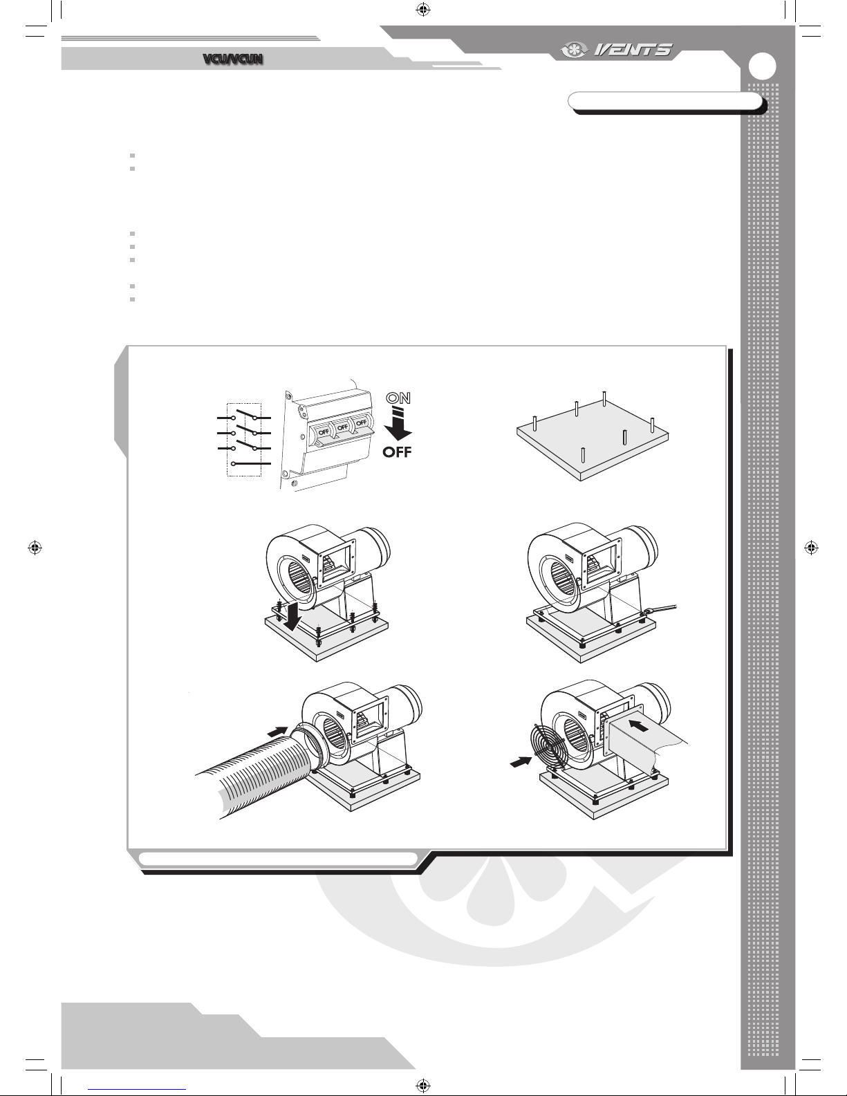
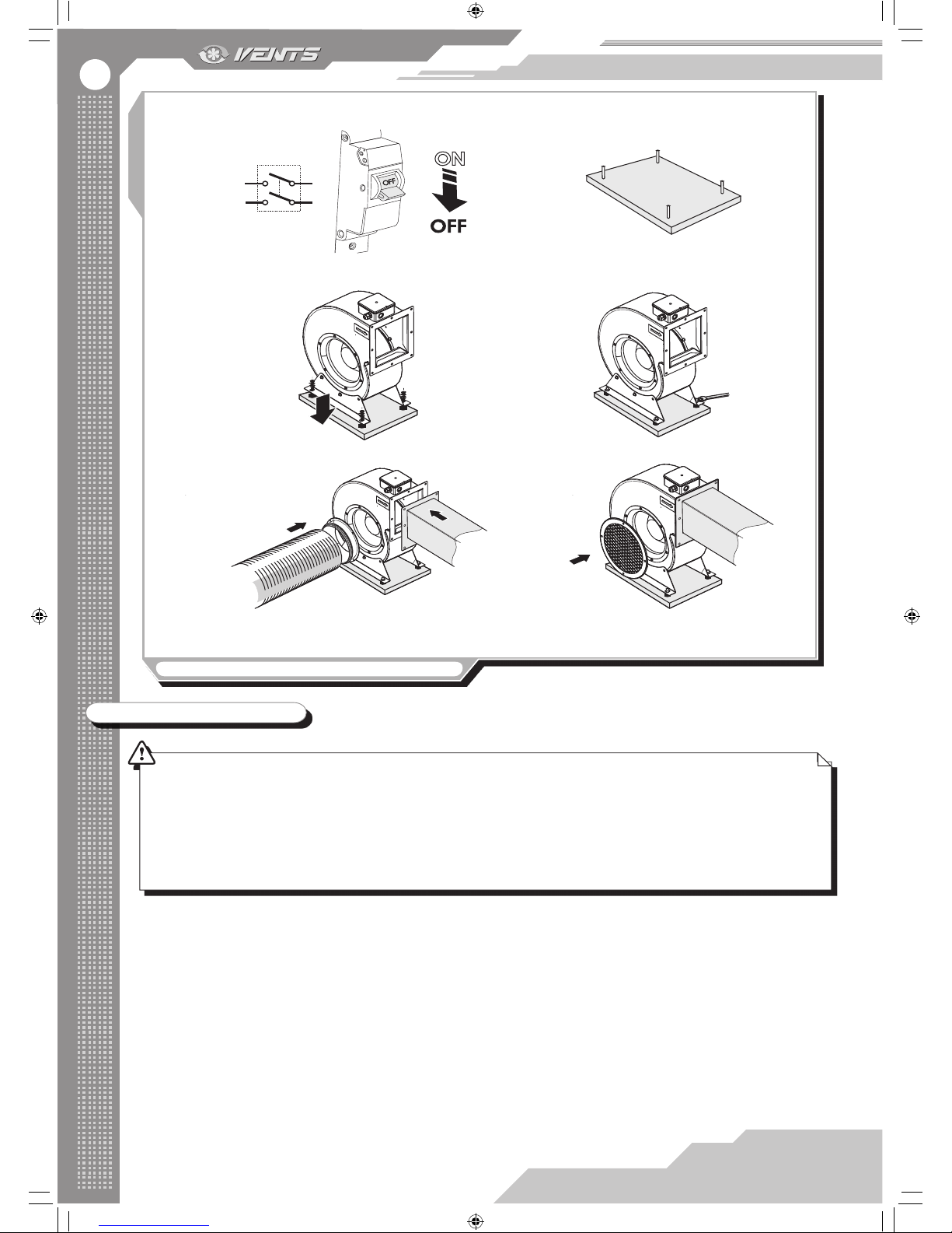
Mounting of the fan as follows:
make sure that the fan is disconnected from power mains, g. 5.1, 6.1;
mark the fastening holes for mounting of the xing bracket on the load-bearing surface, g. 5.2, 6.2;
drill the holes and x the mounting bracket with suitable fasteners, i.e. dowels. Use the anti-vibration mounts VVCr or VVCp
(option) if required, g. 5.3, 6.3;
ground the fan, g. 5.4, 6.4;
connect the air ducts to the fan. Install the FVC-VCU, FVC-VCUN ange (option) on the intake side, g. 5.5, 6.5, table 1, 3 or the
RVC-VCU, RVC-VCUN protecting grille, g. 5.6, 6.6, table 1, 3.
Fig. 5. VCUN fan mounting sequence
S1
PE
1. 2.
3. 4.
5. 6.
V16EN-07.indd 11 03.11.2015 14:25:05
Page 12
12
Fig. 6. VCU fan mounting sequence
1. 2.
3. 4.
5. 6.
S1
CONNECTION TO POWER MAINS
THE FAN MUST BE CONNECTED TO POWER MAINS BY A QUALIFIED ELECTRICIAN AFTER CAREFUL READING OF
THE USER’S MANUAL.
THE FAN IS RATED FOR CONNECTION TO ALTERNATING CURRENT POWER SUPPLY WITH VOLTAGE COMPLIANT
TO THE TECHNICAL DATA TABLE. MAKE SURE THE CABLE IS NOT PRESSED ANYWHERE.
THE RATED ELECTRICAL PARAMETERS OF THE FAN ARE STATED ON THE RATING PLATE. ANY INTERNAL
CONNECTION MODIFICATIONS ARE NOT ALLOWED AND RESULT IN VOID WARRANTY.
VCU fan is rated for connection to single-phase ac 230 V / 50 Hz power mains. VCUN fan is rated for connection to three-phase AC 400
V / 50 Hz power mains.
Connect the fan to power mains by means of insulated, durable and thermal-resistant cords (cables, wires). Install an automatic circuit
breaker at the external electric input and connect it into the house wireworks. Install the external automatic circuit breaker to enable quick
unhampered access to it in case urgent disconnection of the fan is required.
The recommended circuit breaker trip current is determined by the fan model, for more details refer to table 1 and 3. The recommended
cable cross section is stated in the table 5. While selecting the cable type consider the maximum allowable cable heating temperature that
depends on the wire type, insulation, length and layout way (open wire mounting, channel type or wall-mounted).
V16EN-07.indd 12 03.11.2015 14:25:07
Page 13
13
VCU/VCUN
Table 5
Fan model Min. conductor cross section, mm
2
VCU, all fan models 1,5
VCUN 140 .. VCUN 180 1,5
VCUN 200 .. VCUN 400 2,5
VCUN 450 .. VCUN 500 4
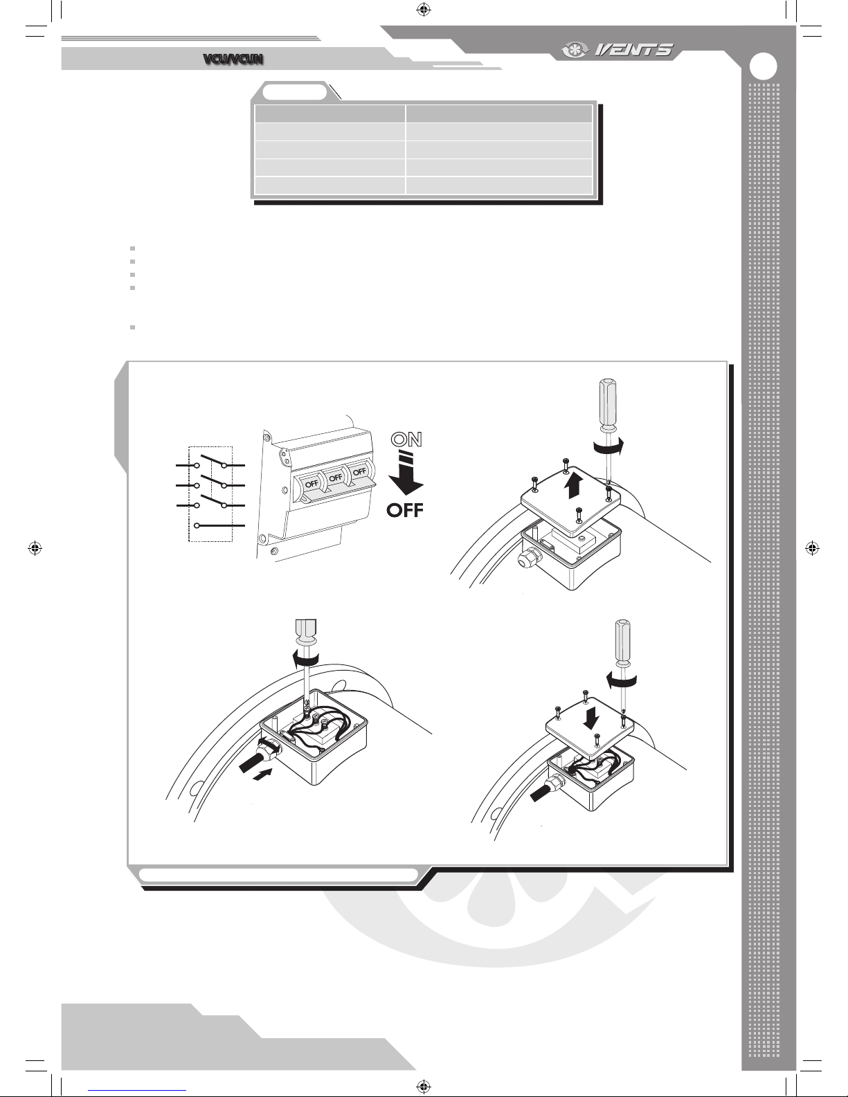
Fig. 7. Connection of VCUN fan to power mains, g. 7
S1
PE
1.
2.
3.
4.
Connection of VCUN fan is as follows, g. 7:
Make sure that power cable is disconnected to power mains, g. 7.1;
Remove the lid of the terminal box located on the motor casing, g. 7.2.
Route the power cable wires through the cable gland on the terminal box, then strip the wires for 7-8 mm, g. 7.3.
Connect the cables to the terminal box in compliance with the wiring diagram. The three-phase motors must be starconnected considering the terminal marking, g. 7.3, 9.4. For doing so, insert the wires into the respective terminals against insulation
stop and x those with the screws.
Cover the terminal box with the lead, g. 7.4.
Air ow direction in the system must match the pointer in the fan casing.
To check the correct impeller rotation start the fan for a short time. If the impeller rotation is wrong, switch over any two phases on
the motor terminals by changing the respective wires in the terminal block.
V16EN-07.indd 13 03.11.2015 14:25:08
Page 14
14
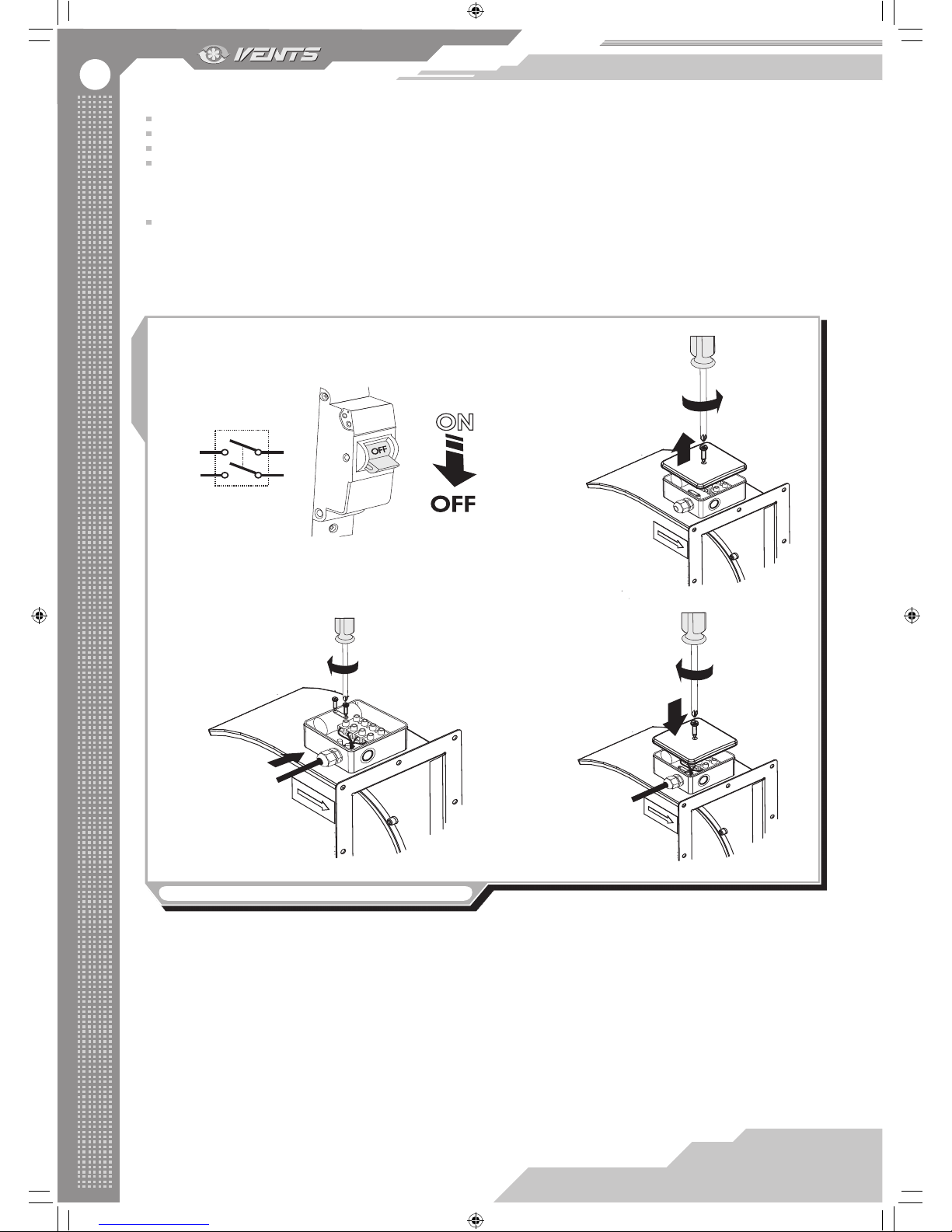
Connection of VCU fan is as follows, g. 8:
make sure that power cable is disconnected to power mains, g. 8.1.
remove the lid of the terminal box located on the motor casing, g. 8.2.
route the power cable wires through the cable gland on the terminal box, then strip the wires for 7-8 mm, g. 8.3.
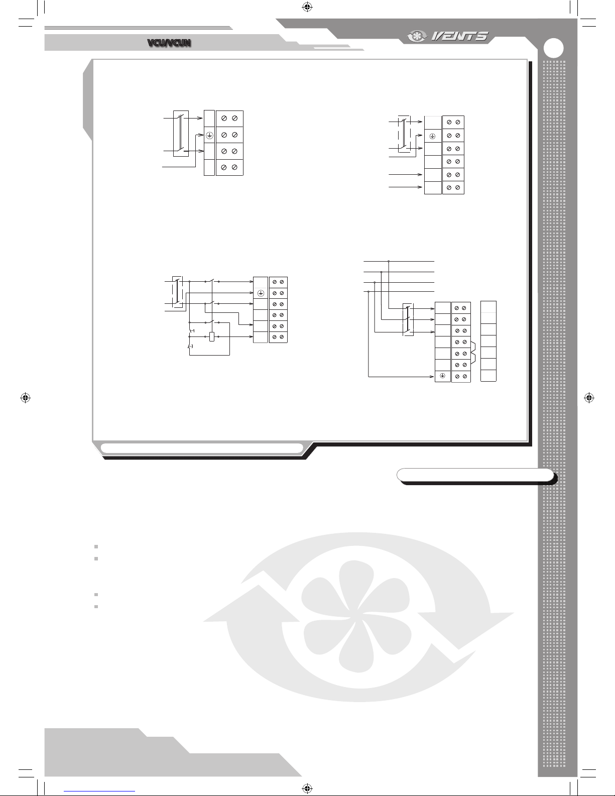
connect the cables to the terminal box in compliance with the wiring diagram and considering the terminal marking. Connection
of the single-phase motors is shown in g. 8.3 and 9.1. Connection of the single-phase motors with external thermal contacts is shown in
g. 9.2. To connect the cable to power mains, insert the wires into the respective terminals against insulation stop in the metal part and x
those with the screws.
cover the terminal box with the lead, g. 8.4.
Connection example of the VCU fan with external thermal protection and a magnetic starter is shown in g. 9.3.
The terminals TW1, TW2 are the electrical leads of the normally closed contact of the motor overheating protection. Connect the
contact in series to the power circuit of the magnetic starter coil that starts the motor. In case of the motor overheating the contact gets
broken and switches the starter coil o to cut power o and stop the motor.
Fig. 8. Connection of VCU fan to power mains
1.
2.
3.
4.
S1
V16EN-07.indd 14 03.11.2015 14:25:09
Page 15
15
VCU/VCUN
Fig. 9. Fan wiring diagrams
QF - automatic circuit breaker
(not included into the delivery set);
X1 - terminal block
1
2
3
4
X1
L
N
QF
L
~230V
50Hz
N
PE
1. VCU
1
2
3
4
5
6
X1
L
N
TW1
TW2
L
~230V
50Hz
N
PE
QF
TW1
TW2
2.
VCU
with a thermal contact
QF - automatic circuit breaker
(not included into the delivery set);
KM1 - magnetic starter
(not included into the delivery set);
S1, S2 - control buttons
(not included into the delivery set);
X1 - terminal block
X1
L
N
1
2
3
4
5
6
TW1
TW2
KM1
L
~230V
50Hz
N
PE
S1
“пуск”
S2
“стоп”
3.
VCU
with a magnetic starter
and a thermal contact
X1
U1
V1
W1
U2
V2
W2
PE
L1
L2
L3
L1
L2
L3
QF
PE
L3
L2
L1
~400V
50Hz
1
2
3
4
5
6
7
QF - automatic circuit breaker
(not included into the delivery set);
X1 - terminal block
4. VCUN
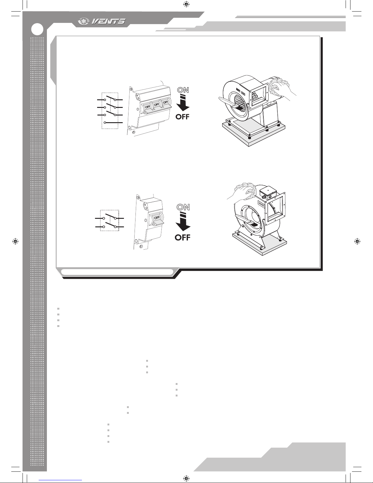
MAINTENANCE
Disconnect the fan from power mains prior to maintenance and servicing operations and make sure that the moving parts have
come to a full stop. The fan maintenance means regular cleaning of the fan surfaces of dust and dirt, g. 10.
Clean the impeller blades thoroughly once in 6 months as follows:
cut o power supply to the fan;
access to the fan impeller:
for VCUN fan: remove the screws and take o the ring;
for VCU fan: remove the screws and pull out the impeller-motor unit;
clean the impeller blades using a dry brush or compressed air;
in case of high soiling wet cleaning is recommended. Clean the impeller blades with a soft cloth wetted in a neutral detergent
solution. Avoid liquid dripping on the motor.
Perform all the operations in the reverse order after cleaning.
V16EN-07.indd 15 03.11.2015 14:25:10
Page 16
16
Fig. 10. Fan maintenance
1. 2.
1.
2.
S1
S1
PE
VCUN
VCU
Maintenance instructions:
Perform regular maintenance of the fan to ensure its reliable, safe and ecient operation.
General maintenance includes:
daily maintenance;
maintenance after each 1000 operation hours;
current repair operations after each 10 000 operating hours;
overhaul repairs after 20 000 operating hours.
All the maintenance works must be carried out according to the schedule above, no matter of the fan operating condition.
Daily fan maintenance must be performed by a mechanician. Current repair operations and overhaul repair operations must be
performed by a mechanician and an electrician responsible for the equipment repair and operation.
Daily maintenance of the fan includes: bolt tightening;
checking of the ground xation reliability;
checking the fan for no noise.
Maintenance after each 1000 operating hours includes: includes all the daily maintenance operations;
troubleshooting of any faults in bolt or welded connections;
checking the clearance between the impeller and the capacitor.
Current repair includes: all the above operations of the maintenance after each 1000 operating hours;
cleaning the casing and the impeller of dirt.
The overhaul repair:
disconnect the air ducts;
disassemble the fan components;
assemble the fan units of new or repair parts;
check the bearing grease and perform adjustment and test running.
V16EN-07.indd 16 03.11.2015 14:25:11
Page 17
17
VCU/VCUN
STORAGE AND TRANSPORTATION RULES
Store the fan in the manufacturer’s original packing box in a dry ventilated premise at the temperatures from +5°C up to + 40°C.
Storage environment must not contain aggressive vapours and chemical mixtures provoking corrosion, insulation and sealing
deformation.
Use hoist machinery for handling and storage operations to prevent the fan damage. Full the handling requirements applicable for
the applicable freight type.
Transportation with any vehicle type is allowed provided that the fan is protected against mechanical and weather damage.
Avoid any mechanical shocks and strokes during handling operations.
MANUFACTURER’S WARRANTY
IN CASE OF WARRANTY CLAIM PLEASE SUBMIT THE USER’S MANUAL AND THE FILLED CONNECTION CERTIFICATE.
THE MANUFACTURER IS NOT RESPONSIBLE FOR ANY DAMAGES RESULTING FROM THE FAN MISUSE OR GROSS
MECHANICAL INTERFERENCE. FOLLOW THE USER’S MANUAL REQUIREMENTS TO ENSURE NON-STOP AND
TROUBLE-FREE OPERATION OF THE FAN.
The manufacturer hereby warrants normal operation of the fan over the period of 24 months from the retail sale date provided the user’s
observance of the transportation, storage, installation and operation regulations.
In case of no conrmation of sales date the warranty period is calculated from the production date.
In case of failures in the fan operation during the warranty period the manufacturer will accept claims and complaints from a customer
only after receiving a technical protocol with a fault description.
The fan damage as a result of unauthorized modications in the electric circuit diagram is not a warranty case.
Both warranty and post-warranty services are carried out at the manufacturing facility. In case of warranty claim please provide the lled
guarantee card with the trade company stamp and the user manual.
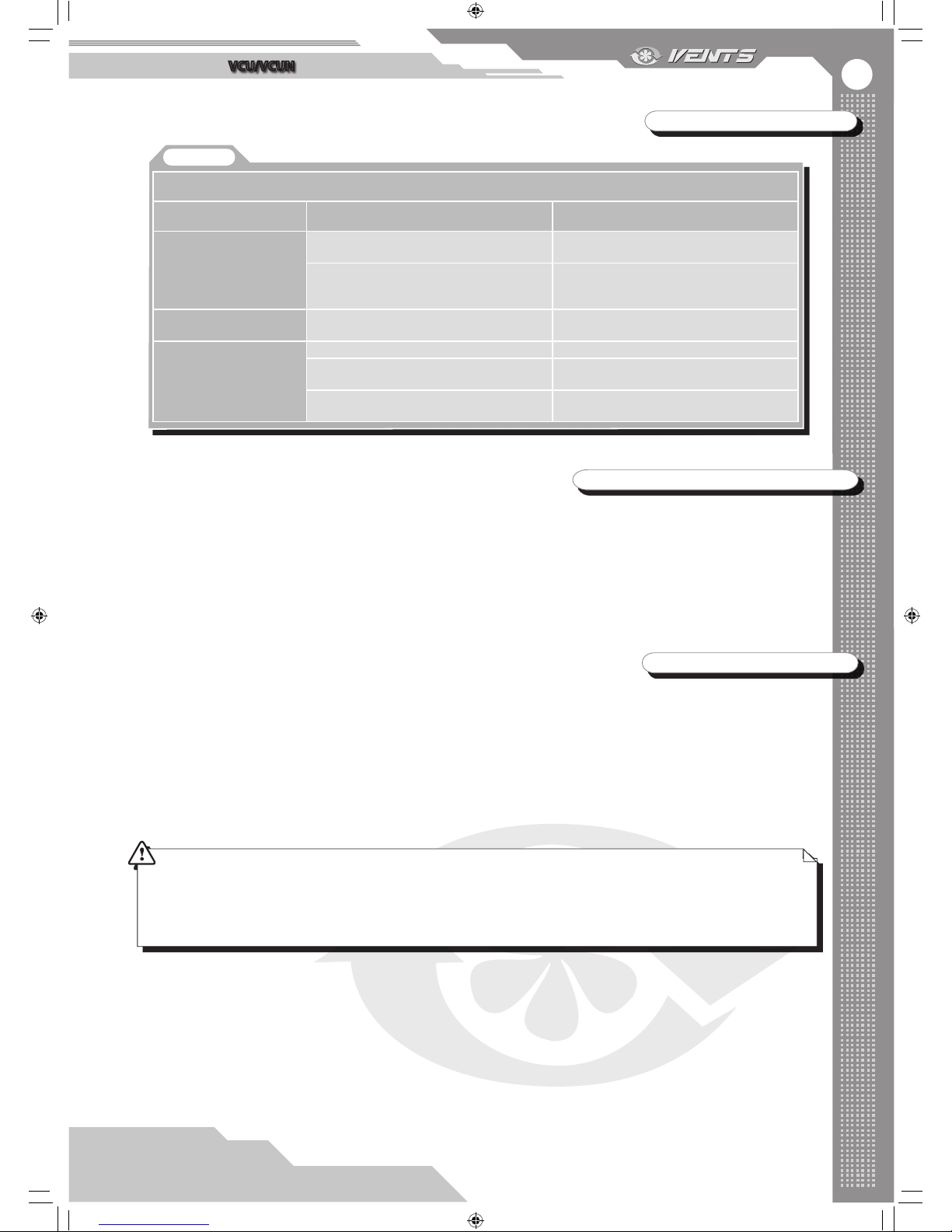
TROUBLESHOOTING
Table 6
Troubles and troubleshooting
Problem
Possible reasons
Fault handling
The fan does not start
No power supply.
Make sure of correct power supply, otherwise
troubleshoot a connection error.
Motor jam.
Turn the fan o. Troubleshoot the motor
jamming. Restart the fan.
Automatic circuit breaker
tripping during the fan start
Overcurrent as a result of short circuit.
Turn the fan o. Contact the service centre.
Noise, vibration
The fan impeller is soiled.
Clean the fan impeller.
Loose screw tightening.
Check the screw connection and tighten the
screws if required.
Resonance with a mounting construction.
Use the suitable recommended VVCr and
VVCp anti-vibration mounts.
V16EN-07.indd 17 03.11.2015 14:25:11
Page 18
18
The centrifugal fan VCU/VCUN _____________________ has been connected to power mains pursuant to the guidelines of the user’s
operation manual by the electrician:
ACCEPTANCE CERTIFICATE
CONNECTION CERTIFICATE
WARRANTY CARD
The centrifugal fan VCU/VCUN_______________________is recognized as serviceable.
We hereby declare that the following product complies with the essential protection requirements of Electromagnetic Council Directive
2004/108/EC, 89/336/EEC and Low Voltage Directive 2006/95/EC, 73/23/EEC and CE-marking Directive 93/68/EEC on the approximation
of the laws of the Member States relating to electromagnetic compatibility.
Quality Inspector’s Stamp Manufacturing Date________________________
Sold by
Company name, stamp of the shop
________________________________________________________________________________________________________________
Sales date_________________________
Company name_____________________________________________________________________________________________________
Installation technician’s full name_______________________________________________________________________________________
Date____________________Signature:___________________________________________________________________________________
__________________________________________________________________________________________________________________
__________________________________________________________________________________________________________________
____________________________________________________________________________________________________
____________________________________________________________________________________________________
____________________________________________________________________________________________________
____________________________________________________________________________________________________
____________________________________________________________________________________________________
____________________________________________________________________________________________________
____________________________________________________________________________________________________
__________________________________________________________________________________________
V16EN-07.indd 18 03.11.2015 14:25:11
Page 19
19
VCU/VCUN
V16EN-07.indd 19 03.11.2015 14:25:11
Page 20

V16EN-07
V16EN-07.indd 20 03.11.2015 14:25:11
 Loading...