

Ventrac LX420 Owner's/operator's Manual
OWNER/OPERATOR’S
MANUAL & PARTS LIST
SNOW BLOWER
Model LX420
Revised 08/26/08
09.10039

Orrville, OH
www.ventrac.com
TO THE OWNER
Product Identification
If you need to contact an Authorized Ventrac Dealer for information on servicing your product,
always provide the Product Model and Serial numbers.
Please fill in the following information for future reference. See picture below to find the loca
tion of the identification number. Record them in the spaces provided below.
-
Date of Purchase: Month _________________ Day ___________ Year ___________________
Dealer: _______________________________________________________________________
Dealer Address: ________________________________________________________________
________________________________________________________________
Dealer Phone Number: __________________________________________________________
Dealer FAX Number: ____________________________________________________________
Model # (A): _______________________
Serial # (B): ________________________
Affix Part/Serial Number label here
Venture Products Inc. reserves the right to make changes
in design or specifications without obligation to make like
changes on previously manufactured products.
ii

TABLE OF CONTENTS
INTRODUCTION SECTION A
Description & Specifications ..................................A-1
SAFETY SECTION B
Safety Symbols ........................................B-1
Decals ............................................. B-2
General Safety Procedures ..................................B-3
Safety Operation & Techniques ................................B-4
OPERATION SECTION C
Attaching ...........................................C-1
Detaching ...........................................C-2
Operating Techniques & Tips .................................C-2
MAINTENANCE/ADJUSTMENTS SECTION D
Bearing Lubrication ...................................... D-1
Gearbox Lubrication ......................................D-1
Belt Replacement .......................................D-1
Chute Adjustment .......................................D-2
Skid Shoe Adjustment .....................................D-2
PARTS & ILLUSTRATED DRAWINGS SECTION E
Main Frame & Auger Drive ................................E-1&2
Main Drive & Fan Drive ..................................E-3&4
Chute & Hydraulics .................................... E-5&6
Shields & Decals .....................................E-7&8
Cutting Edge, Bump Bar, & Skid Shoes .........................E-9&10
PARTS/OPTIONS SECTION F
12 Volt Actuator Deflector Control .............................F-1&2
Weight Transfer for LT3000 Tractors ...........................F-3&4
WARRANTY
iii

INTRODUCTION
Product Description
LX420 Snow Blower
The Ventrac Model LX420 Snow Blower is a powerful, high capacity, two-stage snow blower. It
combines an aggressive sixteen inch auger with a heavy duty, high speed fan to make a powerful and
efficient snow removing attachment for the Ventrac 3000 series tractors.
The LX420 Snow Blower features:
a hydraulic motor that rotates the chute 220 degrees.
•
a reversible, hardened cutting edge.
•
quick attach mounting to the tractor.
•
adjustable skid shoes.
•
optional 12 volt actuator to control the chute deflector angle.
•
Ventrac LX420 Specifications
Overall Height....................................52-1/2 inches
Overall Length .....................................43inches
Overall Width ......................................42inches
Weight ........................................360pounds
Auger Opening Width ..................................38inches
Auger Diameter .....................................16inches
Fan Diameter ....................................19-1/2 inches
Venture Products, Inc. reserves the right to change these specifications without notice.
A-1
SAFETY
ATTENTION:
This symbol identifies potential health and
safety hazards. It marks safety precautions.
Your safety and the safety of others is involved.
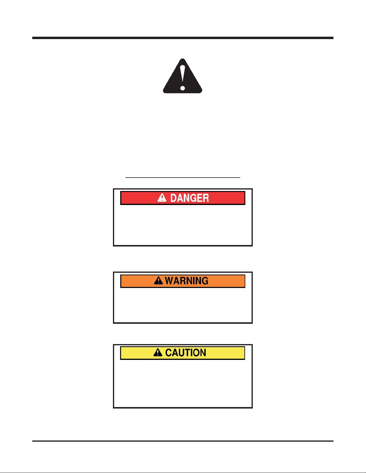
SIGNAL WORD DEFINITIONS
Indicates an imminently hazardous situa-
tion which, if not avoided, will result in
death or serious injury. This signal word is
limited to the most extreme cases.
Indicates a potentially hazardous situation
which, if not avoided, could result in death
or serious injury.
Indicates a potentially hazardous situation
which, if not avoided, may result in minor
or moderate injury and/or property dam
age. It may also be used to alert against
unsafe practices.
-
B-1
SAFETY
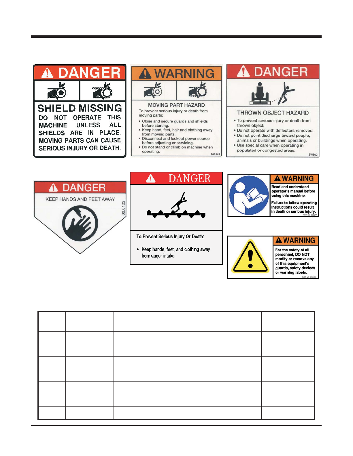
The following decals must be maintained on your Ventrac Attachment. If any decals
are faded or missing, contact your dealer promptly for replacements.
Decal
A
D
Page &
Location
B C
F
E
G
Description Part Number
A
B
C
D
E
F
G
E-7, #5 DECAL, DANGER SHIELD MISSING 00.0062
E-7, #18 DECAL, HAZARD-MOVING PART 00.0101
E-7, #17 DECAL, THROWN OBJECT HAZARD 00.0122
E-5, #34 (2) DECAL, KEEP HAND AND FEET AWAY 00.0123
E-7, #6 (2) DECAL, DANGER AUGER HAZARD 00.0208
E-7, #23 DECAL, WARNING READ OWNERS MAN 00.0217
E-7, #23 DECAL, GENERAL SAFETY 00.0220
B-2

SAFETY
General Safety Procedures
for Ventrac Tractors, Attachments, & Accessories
Read and understand the operator’s manual before operating this equipment.
Observe and follow all safety decals.
DO NOT let children or any untrained person operate the tractor or attachment. Make sure that all
operators of this equipment are thoroughly trained in using it safely.
Never allow additional riders on the tractor or attachments.
DO NOT operate tractor or attachments if you are under the influence of alcohol, drugs, or medication
that may impair judgment or cause drowsiness, or if you are not feeling well.
Operate all controls from the operator’s seat only.
Before operating equipment, make sure all shields are in place and fastened.
Ensure the attachment or accessory is locked or fastened securely to the tractor before operating.
See tractor manual for locking procedure.
Ensure that all bystanders are clear of the tractor and attachment before operating. Be especially
careful and observant if other people are present. Never assume that bystanders will remain where
you last saw them.
Always look in the direction the tractor is moving.
Never direct the discharge of any attachment in the direction of people, animals, buildings, vehicles,
or objects of value.
Stop operation immediately at any sign of equipment failure and correct the problem before
continuing to operate. An unusual noise can be a warning of equipment failure or a sign that
maintenance is required.
Before adjusting, cleaning, lubricating, or changing parts on the tractor or attachment, engage the
parking brake, lower the attachment to the ground, stop the engine, and remove the ignition key.
To prevent the risk of uncontrolled equipment movement on tractors equipped with 2 speed axles,
always shift the transaxle range with the tractor stationary on level ground and with the parking brake
engaged.
If equipment is to be left unattended, engage the parking brake, lower the attachment to the ground,
stop the engine, and remove the ignition key.
B-3
SAFETY
LX420 Safety Procedures
Before making any repairs or adjustments, engage
the parking brake, lower attachment to the ground,
shut the engine off, and remove the key.
Never direct the snow blower discharge chute to
ward people, animals, buildings, vehicles, or other
personal property. Debris can be thrown from the
chute causing damage, serious injury, or death.
Read and understand the operator’s manual
before operating this equipment.
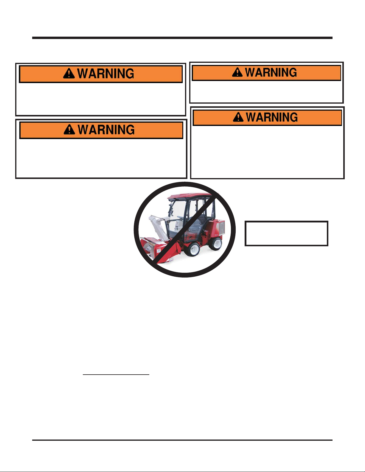
Before operating any LX420 prior to serial
AB1135 with a LE3100 or LE3200 that is
equipped with a tractor cab, a new center post
(Kit #70.3022) must be installed, or the tractor
cab must be removed. Damage may occur to
the cab if proper precaution is not followed.
See Warning Above
Before Operating the
LX420 with a LE Cab!
Never operate snow blower when people are in the area. Frozen snow, ice, gravel, and other objects
can be thrown at lethal velocity.
Operators should be familiar with the area they are clearing and make preparations ahead of time.
Place guide stakes appropriately and remove stones, markers, or other debris that may be hidden
after a snowfall. Curbs, offsets, steps, man hole covers, broken or raised pavement, etc. should be
noted. Operators should map areas to be cleared before the winter season so they can review
potential hazards prior to clearing snow in the area.
If an area is to be cleared that is unfamiliar to the operator, travel slowly and use EXTREME
CAUTION. Inquire of anyone who might know of potential hazards.
The operator should never proceed if visibility is poor. If the tractor is equipped with a cab, the
windshield must be kept clean.
Discharge snow with the wind direction
blowing distance and visibility.
Use caution when operating around objects that can obstruct your vision.
Shut off the PTO when you are not blowing snow.
Always shut off the PTO and engage the parking brake before dismounting to change the angle of the
discharge chute deflector.
Never travel at speeds that would cause injury to the operator or damage to the machine, if the
machine were to be stopped suddenly by an unseen, immovable object.
as much as possible. Discharging into the wind reduces
B-4
OPERATION
Attaching
1. Drive the tractor slowly forward into the hitch arms on the snow blower. Align the lift arms of the
tractor with the snow blower hitch arms by raising or lowering the front hitch and complete the
engagement.
2. Once completely engaged, close the front hitch locking lever
3. Raise snow blower to the highest position, engage the parking brake*, and shut off the engine.
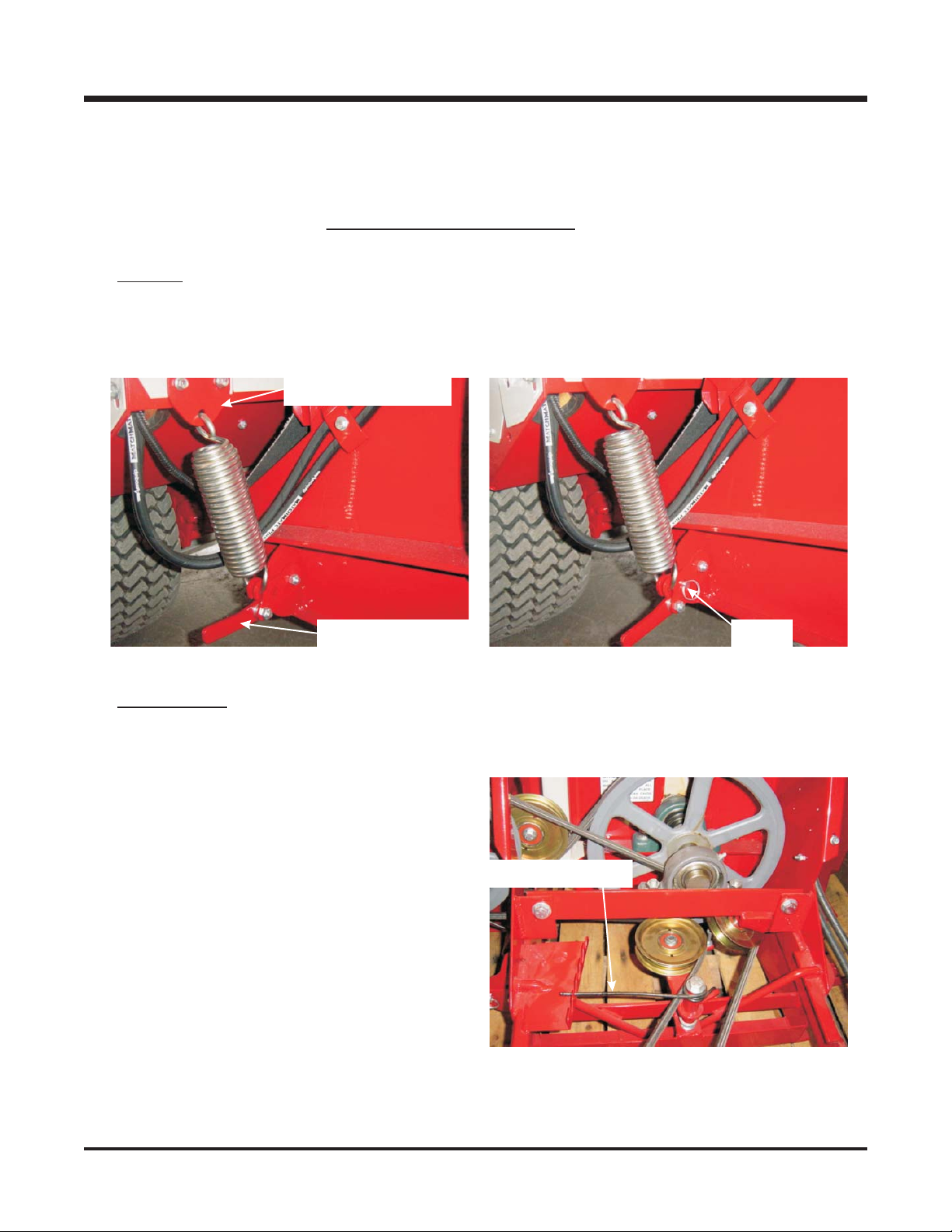
4.
LT3000:
hook through the hole on the upper spring mounting bracket and slip the other spring hook over
the spring anchor lever on the snow blower (Fig 1). Rotate the spring anchor lever down until the
hole is aligned with one of the holes on the main frame. The lowest hole is recommended. Insert
the ball pin to secure. See (Fig 2).
Place blocks underneath the snow blower to prevent it from lowering. Insert the spring
Spring mount bracket
.*
Spring anchor lever Ball pin
Figure 1 Figure 2
LE3100-3200:
able. (Note: If your LE3100 is not equipped with weight transfer, part # 70.3014 must be ordered).
5. Place the attachment belt over the outside groove of the PTO drive pulley on the tractor. Ensure
the belt is properly seated in each pulley.
6. Engage the PTO belt tension spring on the
snow blower. See Figure 3. Belt tension can
be adjusted by moving the belt tension spring
to a different slot. See belt tension adjustment
on page D-2.
7. Wipe the quick couplers clean, and connect to
the tractor. If equipped, connect the hoses and
quick couplers so the red indicators are paired
together and the yellow indicators are paired
together.
8. Connect the electric plug. (if equipped)
Set the weight transfer system* to the maximum amount of weight transfer allow-
Belt tension spring
* Refer to tractor manual for operation of
controls.
Figure 3
C-1
 Loading...