

Ventrac LM600, LM520 Operator Manual & Illustrated Parts List
OperatOr’s Manual
& parts Drawings
MOwer
MODel lM520 serial nuMber 1923 --
MODel lM600 serial nuMber 1335 --
Original Operator’s Manual
Revised 03/09/16
09.10062 Rev. 03

500 Venture Drive
PO Box 148
Orrville Oh 44667
www.ventrac.com
To the Owner
Contact Information and Product Identication
If you need to contact an authorized Ventrac dealer for information on servicing your product,
always provide the product model and serial numbers.
Please ll in the following information for future reference. See the picture(s) below to nd the
location of the identication numbers. Record them in the spaces provided.
Date of Purchase: _______________________________________________________
Dealer: ________________________________________________________________
Dealer Address: _________________________________________________________
_________________________________________________________
Dealer Phone Number: ___________________________________________________
Dealer Fax Number: _____________________________________________________
Model # (A): _____________________
Serial # (B): _____________________
Afx Part/Serial Number label here.
A
B
Venture Products Inc. reserves the right to make chang-
es in design or specications without obligation to make
like changes on previously manufac
2
tured products.

Blank Page

TABLE OF CONTENTS
INTRODUCTION PAGE 6
Product Description ................................................................................................................................ 6
Why Do I Need an Operator’s Manual? ................................................................................................. 6
Using Your Manual ................................................................................................................................. 7
Manual Glossary ....................................................................................................................................7
SAFETY PAGE 8
Safety Decals ......................................................................................................................................... 8
Training Required .................................................................................................................................10
Personal Protective Equipment Requirements ....................................................................................10
Operating Safely ..................................................................................................................................10
General Safety Procedures .................................................................................................................. 10
Preventing Accidents ............................................................................................................................ 11
Keep Riders Off .................................................................................................................................... 11
Operating On Slopes ............................................................................................................................12
Roadway Safety ................................................................................................................................... 12
Truck Or Trailer Transport ....................................................................................................................12
Maintenance ......................................................................................................................................... 13
Fuel Safety ........................................................................................................................................... 13
Hydraulic Safety ................................................................................................................................... 14
Cutting Unit Safety ...............................................................................................................................15
OPERATIONAL CONTROLS PAGE 16
Operational Control Locations ..............................................................................................................16
Main Belt Tensioner (A) ........................................................................................................................16
Height Adjustment Handle (B) .............................................................................................................. 16
GENERAL OPERATION PAGE 17
Daily Inspection .................................................................................................................................... 17
Attaching ..............................................................................................................................................17
Detaching ............................................................................................................................................. 17
Mowing and Operating Procedure .......................................................................................................17
Transport of Mower ..............................................................................................................................18
Cutting Height Adjustment .................................................................................................................... 18
Mulching Kit (Optional Accessory) ....................................................................................................... 18
SERVICE PAGE 19
Cleaning and General Maintenance.....................................................................................................19
Deck Flip-Up Procedure (Service Position) ..........................................................................................19
Mower Blade Removal & Installation ...................................................................................................19
Sharpening Blades ............................................................................................................................... 19
Deck Belt Inspection ............................................................................................................................19
Tire Pressure ........................................................................................................................................20
Deck Leveling Procedure ..................................................................................................................... 20
Lubrication ............................................................................................................................................ 21
Storage ................................................................................................................................................. 21
Maintenance Schedule .........................................................................................................................22
Maintenance Checklist ......................................................................................................................... 22
4

TABLE OF CONTENTS
SPECIFICATIONS PAGE 23
LM520 Dimensions ..............................................................................................................................23
LM600 Dimensions ..............................................................................................................................23
Features ............................................................................................................................................... 23
PARTS PAGE 24
Main Deck ............................................................................................................................................24
Carrier Frame ....................................................................................................................................... 26
Front Caster Wheels & Rear Roller ......................................................................................................28
Hitch Assembly ..................................................................................................................................... 30
Spindles & Blades ................................................................................................................................ 32
39.35150 LM520 Mulching Kit ..............................................................................................................34
39.35151 LM600 Mulching Kit ..............................................................................................................34
WARRANTY PAGE 36
5
INTRODUCTION
enture Products Inc. is pleased to provide you with your new
V
Ventrac mower! We hope that Ventrac equipment will provide
you with a ONE Tractor Solution.
Listed below are just some of the items that can provide you
versatility as you use your LM520 or LM600. Please visit our
web site, or contact your authorized Ventrac dealer for a complete list of items available for your new mower.
Accessories
Item Description
LM520 Mulching Kit 39.35150
Blade, RH Mulch (requires 3 per mower) 79.0057
LM600 Mulching Kit 39.35151
Blade, RH Mulch (requires 3 per mower) 79.0051
Part Number
Product Description
The LM520 and LM600 mowers were designed for the sole purpose of nish mowing. The LM520 features
a 52 inch (132 cm) cutting width, and the LM600 features a 60 inch (152 cm) cutting width.
The LM series mowers utilize a rugged all steel frame design which suspends the Ventrac’s mower deck.
This design gives you a high efciency grass discharge for a better quality of cut by moving more grass efciently through the deck tunnel. The mowers are equipped with a full widt h rear roller and wide pneumatic
front swivel tires that oat over terrain independent of the power unit.
LAS, a unique Linear Adjustment System, provides cutting height selections between 1-1/2 and 3-3/4 inches
(3.8 and 9.5 cm). A single handle with a slight outward pull allows for a quick and easy change in cutting
height selection. A slide release allows the handle to be returned to deck level, preventing it from catching on
low branches and shrubs.
With the removal of two pins beneath the cross frame, the deck can be easily tilted to a near vertical position for maintenance and storage.
All Ventrac LM nish mowers feature a full width rear roller for the ultimate in yard striping. These professional grade mowers are built to give you maximum performance and productivity.
Why Do I Need an Operator’s Manual?
This manual has been created to help you gain the important knowledge of what is needed to safely
operate, maintain, and service your machine. It is divided into sections for convenient reference of the
appropriate section.
You must read and understand the operator’s manual for each piece of Ventrac equipment you own. Reading the operator’s manual will help you become familiar with each specic piece of equipment. Understanding the operator’s manual will help you, as well as others, avoid personal injury and/or damage to the
equipment. Keep this manual with the machine at all times. The manual should remain with the machine
even if it is sold. If this manual becomes damaged or unreadable, it should be replaced immediately. Contact your local Ventrac dealer for a replacement.
When using a Ventrac attachment, be sure to read and follow the safety and operating instructions of both
the power unit and the attachment being used to ensure the safest operation possible.
The information in this manual provides the operator with the safest procedures to operate the machine
while getting the maximum use out of the unit. Failure to follow the safety precautions listed in this manual
may result in personal injury and/or damage to the equipment.
Introduction - 6
INTRODUCTION
Using Your Manual
Throughout this manual, you will encounter special messages and symbols that identify potential safety
concerns to help you as well as others avoid personal injury or damage to the equipment.
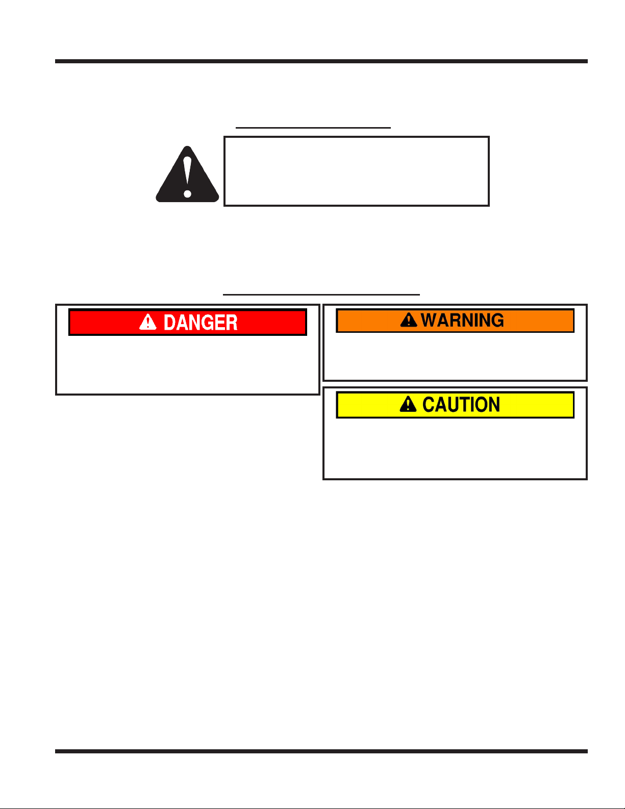
SYMBOL DEFINITIONS
ATTENTION
This symbol identies potential health and
safety hazards. It marks safety precautions.
Your safety and the safety of others is involved.
There are three signal words that describe the level of safety concern: Danger, Warning, and Caution.
Safety should always be the #1 priority when working on or operating equipment. Accidents are more likely
to occur when proper operating procedures are not followed or inexperienced operators are involved.
Note: Right-Hand and Left-Hand orientations may be referred to at different places throughout this manual.
Right-Hand and Left-Hand is determined as if sitting on the power unit seat facing forward.
SIGNAL WORD DEFINITIONS
Indicates an imminently hazardous situation
which, if not avoided, will result in death or
serious injury. This signal word is limited to the
most extreme cases.
Indicates a potentially hazardous situation
which, if not avoided, could result in death or
serious injury.
Indicates a potentially hazardous situation
which, if not avoided, may result in minor or
moderate injury and/or property damage. It may
also be used to alert against unsafe practices.
Manual Glossary
Power Unit A Ventrac tractor or other Ventrac engine powered device that may be operated by itself or
with an attachment or accessory.
Attachment A piece of Ventrac equipment that requires a Power Unit for operation.
Accessory A device that attaches to a Power Unit or Attachment to extend its capabilities.
Machine Describes any “Attachment” or “Accessory” that is used in conjunction with a power unit.
Introduction - 7

SAFETY
Safety Decals
The following safety decals must be maintained on your LM series mower.
Keep all safety decals legible. Remove all grease, dirt, and debris from safety decals and instructional
labels. If any decals are faded, illegible, or missing, contact your dealer promptly for replacements.
When new components are installed, be sure that current safety decals are afxed to the replacement
components.
A
E
F
C
B
E
D
Safety - 8
E

SAFETY
Decal Description Part Number Quantity
A Danger, Shield Missing 00.0062 1
B Warning - Moving Part Hazard 00.0101 1
C Danger, Pinching Hazard 00.0102 1
D Danger, Thrown Object Hazard 00.0122 1
E Danger, Keep Hands & Feet Away 00.0123 3
F Warning, Read Owner’s Manual 00.0217 1
Safety - 9

SAFETY
General Safety Procedures
for Ventrac Power Units, Attachments, & Accessories
Training Required
• The owner of this machine is solely responsible for properly training the operators.
• The owner/operator is solely responsible for the operation of this
machine and prevention of accidents or injuries occurring to him/herself, other people, or property.
• Do not allow operation or service by children or untrained personnel.
Local regulations may restrict the age of the operator.
• Before operating this machine, read the operator’s manual and understand its contents.
• If the operator of the machine cannot understand this manual, then it
is the responsibility of this machine’s owner to fully explain the material
within this manual to the operator.
• Learn and understand the use of all controls.
• Know how to stop the power unit and all attachments quickly in the event of an emergency.
Personal Protective Equipment Requirements
It is the responsibility of the owner to be sure that the operators use the proper personal protective equipment while operating the machine. Required personal protective equipment includes, but is not limited to,
the following list.
• Wear a certied ear protection device to prevent loss of hearing.
• Prevent eye injury by wearing safety glasses while operating the machine.
• Closed toe shoes must be worn at all times.
• Long pants must be worn at all times.
• When operating in dusty conditions, it is recommended that a dust mask be worn.
Operation Safety
• Inspect machine before operation. Repair or replace any damaged, worn, or missing parts. Be sure
guards and shields are in proper working condition and are secured in place. Make all necessary
adjustments before operating machine.
• Some pictures in this manual may show shields or covers opened or removed in order to clearly illustrate
any instructions. Under no circumstance should the machine be operated without these devices in place.
• Alterations or modications to this machine can reduce safety and could cause damage to the machine.
Do not alter safety devices or operate with shields or covers removed.
• Before each use, verify that all controls function properly and inspect all safety devices. Do not operate
if controls or safety devices are not in proper working condition.
• Check parking brake function before operating. Repair or adjust parking brake if necessary.
• Observe and follow all safety decals.
• All controls are to be operated from the operator’s seat only.
• Always wear a seat belt if the machine has a roll cage/bar installed and in upright position.
• Ensure the attachment or accessory is locked or fastened securely to the power unit before operating.
• Ensure that all bystanders are clear of the power unit and attachment before operating. Stop machine if
someone enters your work area.
• Always be alert to what is happening around you, but do not lose focus on the task you are performing.
Always look in the direction the machine is moving.
• Look behind and down before backing up to be sure of a clear path.
• If you hit an object, stop and inspect the machine. Make all necessary repairs before operating machine again.
• Stop operation immediately at any sign of equipment failure. An unusual noise can be a warning of equipment
failure or a sign that maintenance is required. Make all necessary repairs before operating machine again.
Safety - 10
SAFETY
General Safety Procedures
for Ventrac Power Units, Attachments, & Accessories
Operation Safety (continued)
• If equipped with a high/low range feature, never shift between high and low range while on a slope.
Always move the machine to level ground and engage the parking brake before shifting range.
• Do not leave machine unattended while it is running.
• Always park the machine on level ground.
• Always shut off engine when connecting attachment drive belt to the power unit.
• Never leave the operator’s seat without lowering the attachment to the ground, setting the parking
brake, shutting off the engine, and removing the ignition key. Make sure all moving parts have come to
a complete stop before dismounting.
• Never leave equipment unattended without lowering the attachment to the ground, setting the parking
brake, shutting off the engine, and removing the ignition key.
• Only operate in well-lit conditions.
• Do not operate when there is a risk of lightning.
• Never direct the discharge of any attachment in the direction of people, buildings, animals, vehicles, or
other objects of value.
• Never discharge material against a wall or obstruction. Material may ricochet back towards the operator.
• Use extra caution when approaching blind corners, shrubs, trees, or other objects that may obscure vision.
• Do not run the engine in a building without adequate ventilation.
• Do not touch the engine or the mufer while the engine is running or immediately after stopping the engine.
These areas may be hot enough to cause a burn.
• Do not change the engine governor settings or over-speed the engine. Operating engine at excessive speed
may increase the hazard of personal injury.
• To reduce the hazard of re, keep the battery compartment, engine, and mufer areas free of grass, leaves,
and excessive grease.
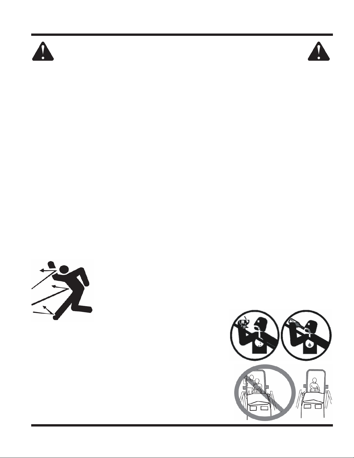
Preventing Accidents
• Clear working area of objects that might be hit or thrown from machine.
• Keep people and pets out of mowing area.
• Know the work area well before operation. Do not operate where traction or
stability is questionable.
• Reduce speed when you are operating over rough ground.
• Equipment can cause serious injury and/or death when improperly used.
Before operating, know and understand
the operation and safety of the power
unit and the attachment being used.
• Do not operate machine if you are not in good physical and
mental health, if you will be distracted by personal devices, or are
under the inuence of any substance which might impair decision, dexterity, or judgment.
• Children are attracted to machine activity. Be aware of children
and do not allow them in the working area. Turn off the machine if
a child enters the work area.
Keep Riders Off
• Only allow the operator on the power unit. Keep riders off.
• Never allow riders on any attachment or accessory.
Safety - 11
SAFETY
General Safety Procedures
for Ventrac Power Units, Attachments, & Accessories
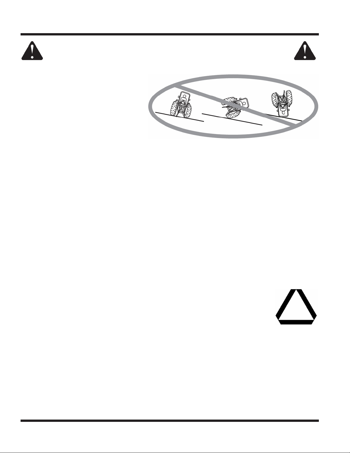
Operating On Slopes
• Slopes can cause loss-of-control and
tip-over accidents, which can result in
severe injury or death. Be familiar with the
emergency parking brake, along with the
power unit controls and their functions.
• If power unit is equipped with a fold down
roll bar, it must be locked in the upright
position when operating on any slope.
• Use low range (if equipped) when operating
on slopes greater than 15 degrees.
• Do not stop or start suddenly when operating on slopes.
• Never shift between high and low range while on a slope. Always move the power unit to level ground
and engage the parking brake before shifting range or placing the power unit in neutral.
• Variables such as wet surface and loose ground will reduce the degree of safety. Do not drive where
machine could lose traction or tip over.
• Keep alert for hidden hazards in the terrain.
• Stay away from drop-offs, ditches, and embankments.
• Sharp turns should be avoided when operating on slopes.
• Pulling loads on hills decreases safety. It is the responsibility of the owner/operator to determine loads
that can safely be controlled on slopes.
• Transport machine with attachment lowered or close to the ground to improve stability.
• While operating on slopes, drive in an up and down direction when possible. If turning is necessary
while driving across slopes, reduce speed and turn slowly in the downhill direction.
• Assure a sufcient supply of fuel for continuous operation. A minimum of one-half tank of fuel is recommended.
Roadway Safety
• Operate with safety lights when operating on or near roadways.
• Obey all state and local laws concerning operation on roadways.
• Slow down and be careful of trafc when operating near or crossing roadways. Stop before crossing
roads or sidewalks. Use care when approaching areas or objects that may obscure vision.
• If there is doubt of safety conditions, discontinue machine operation until a time when
operation can be performed safely.
• When operating near or on roadways, have a Slow Moving Vehicle Emblem clearly
displayed.
Truck Or Trailer Transport
• Use care when loading or unloading machine into a truck or trailer.
• Use full width ramps for loading machine into a truck or trailer.
• The parking brake is not sufcient to lock the machine during transport. Always secure the power unit
and/or attachment to the transporting vehicle securely using straps, chains, cable, or ropes. Both front
and rear straps should be directed down and outward from the machine.
• Shut off fuel supply to power unit during transport on truck or trailer.
• If equipped, turn the battery disconnect switch to the Off position to shut off electrical power.
Safety - 12
 Loading...