

Ventrac KX523 Operator's Manual
OperatOr’s Manual
& parts Drawings
snOw BlOwer
MODel KX523
Original Operator’s Manual
Revised 08/31/15
09.10059 Rev. 03

500 Venture Drive
PO Box 148
Orrville Oh 44667
www.ventrac.com
To the Owner
Contact Information and Product Identication
If you need to contact an authorized Ventrac dealer for information on servicing your product,
always provide the product model and serial numbers.
Please ll in the following information for future reference. See the picture(s) below to nd the
location of the identication numbers. Record them in the spaces provided.
Date of Purchase: __________________________________________________________________
Dealer: ___________________________________________________________________________
Dealer Address: ____________________________________________________________________
____________________________________________________________________
Dealer Phone Number: ______________________________________________________________
Dealer Fax Number: ________________________________________________________________
Model # (A): __________________________
Serial # (B): __________________________
Afx Part/Serial Number label here.
A
B
Venture Products Inc. reserves the right to make changes
in design or specications without obligation to make like
changes on previously manufactured products.
2

TABLE OF CONTENTS
INTRODUCTION PAGE 5
Product Description ................................................................................................................................ 5
Why Do I Need an Operator’s Manual? ................................................................................................. 5
Using Your Manual ................................................................................................................................. 6
Manual Glossary ....................................................................................................................................6
SAFETY PAGE 7
Safety Decals ......................................................................................................................................... 7
General Safety Procedures .................................................................................................................... 9
Training Required ...................................................................................................................................9
Personal Protective Equipment Requirements ......................................................................................9
Operation Safety ....................................................................................................................................9
Preventing Accidents ............................................................................................................................10
Keep Riders Off ....................................................................................................................................10
Operating On Slopes ............................................................................................................................ 11
Roadway Safety ................................................................................................................................... 11
Truck Or Trailer Transport .................................................................................................................... 11
Maintenance ......................................................................................................................................... 12
Fuel Safety ........................................................................................................................................... 12
Hydraulic Safety ................................................................................................................................... 13
KX523 Snow Blower Safety Procedures .............................................................................................. 14
OPERATIONAL CONTROLS PAGE 15
Discharge Chute Rotation (A) ..............................................................................................................15
Discharge Chute Adjustment Link (B) .................................................................................................. 15
Optional Discharge Chute Deector Actuator Control (C) ....................................................................15
GENERAL OPERATION PAGE 16
Daily Inspection .................................................................................................................................... 16
Attaching ..............................................................................................................................................16
Detaching ............................................................................................................................................. 16
Snow Blower Operating Procedure ...................................................................................................... 16
Transport of Snow Blower ....................................................................................................................17
Discharge Chute Rotation .................................................................................................................... 17
Discharge Chute Deector Adjustment (Optional Actuator Control).....................................................17
Rear Skid Shoe Adjustment ................................................................................................................. 17
Front Skid Shoe Adjustment ................................................................................................................. 17
Clearing a Blockage ............................................................................................................................. 18
3

TABLE OF CONTENTS
SERVICE PAGE 19
Cleaning & General Maintenance ........................................................................................................19
Cutting Edge Reversal/Replacement ................................................................................................... 19
Skid Shoe Replacement .......................................................................................................................19
Vertical Cutting Edge Adjustment ......................................................................................................... 19
Belt Inspection/Replacement ...............................................................................................................19
Gearbox Drive Belt Replacement .........................................................................................................20
Auger Drive Belt Replacement ............................................................................................................. 20
Deep Snow Auger Drive Belt Replacement ......................................................................................... 20
Belt Tension Adjustment ....................................................................................................................... 20
Lubrication Locations ...........................................................................................................................21
Gearbox ...............................................................................................................................................21
Storage ................................................................................................................................................. 21
Maintenance Schedule .........................................................................................................................22
Maintenance Checklist ......................................................................................................................... 22
SPECIFICATIONS PAGE 23
Dimensions ..........................................................................................................................................23
Features ............................................................................................................................................... 23
PARTS PAGE 24
Main Frame & Auger ............................................................................................................................ 24
PTO Drive & Gearbox Drive .................................................................................................................26
Gearbox & Auger Drive ........................................................................................................................ 28
Fan & Fan Shaft ................................................................................................................................... 30
Fan Drive .............................................................................................................................................. 32
Discharge Chute ..................................................................................................................................34
Discharge Chute Rotation Drive ...........................................................................................................36
Discharge Chute Guard & Cleaning Tool .............................................................................................38
Drive Shields ........................................................................................................................................ 40
Skid Shoes, Cutting Edge, & Crossbar Guard .....................................................................................42
70.8025 12 Volt Actuator ...................................................................................................................... 44
70.8072 Deep Snow Auger Kit ............................................................................................................. 46
WARRANTY PAGE 48
4
INTRODUCTION
INTRODUCTION
enture Products Inc. is pleased to provide you with your new
V
Ventrac snow blower! We hope that Ventrac equipment will
provide you with a ONE Tractor Solution.
Listed below are just some of the items that can provide you
versatility as you use your snow blower. Please visit our web
site, or contact your authorized Ventrac dealer for a complete
list of items available for your new snow blower.
KX523
Accessories
*Power unit must be equipped with a 12 volt front switch & plug.
Power Unit
Accessories
Item Description
12 Volt Actuator Kit* 70.8025
Deep Snow Top Auger Kit 70.8072
Item Description
12 Volt Switch & Plug Kit (HT4000) 70.4046
12 Volt Switch & Plug Kit (KT4100 & KT4200) 70.4039
12 Volt Switch & Plug Kit (KN4500) 70.4104
Weight Transfer Kit for KT4100 70.0104
Weight Transfer Kit for KN4500K 70.4115
Part Number
Part Number
Product Description
The Ventrac Model KX523 Snow Blower is designed for the sole purpose of blowing snow. It is a powerful,
high capacity, two stage snow blower that moves large amounts of snow quickly.
The snow blower’s large 16” (40.6 cm) auger funnels the snow into the high speed fan which throws the
snow up to 40 feet (12.2 m) away from the operation area.
The discharge chute is hydraulically controlled. The operator controls the direction of the discharge from
the operator’s seat of the power unit.
An optional 12 volt actuator kit (70.8025) can be purchased to allow the operator to control the throw distance of the snow blower from the operator’s seat of the power unit.
For areas with heavy snowfall, an optional deep snow (top auger) kit (70.8072) is available. The deep snow
kit mounts a small auger above the main auger for effective removal of deeper snow.
Why Do I Need an Operator’s Manual?
This manual has been created to help you gain the important knowledge of what is needed to safely
operate, maintain, and service your machine. It is divided into sections for convenient reference of the
appropriate section.
You must read and understand the operator’s manual for each piece of Ventrac equipment you own. Reading the operator’s manual will help you become familiar with each specic piece of equipment. Understanding the operator’s manual will help you, as well as others, avoid personal injury and/or damage to the
equipment. Keep this manual with the machine at all times. The manual should remain with the machine
even if it is sold. If this manual becomes damaged or unreadable, it should be replaced immediately. Contact your local Ventrac dealer for a replacement.
When using a Ventrac attachment, be sure to read and follow the safety and operating instructions of both
the power unit and the attachment being used to ensure the safest operation possible.
The information in this manual provides the operator with the safest procedures to operate the machine
while getting the maximum use out of the unit. Failure to follow the safety precautions listed in this manual
may result in personal injury and/or damage to the equipment.
Introduction - 5
INTRODUCTION
Using Your Manual
Throughout this manual, you will encounter special messages and symbols that identify potential safety
concerns to help you as well as others avoid personal injury or damage to the equipment.
SYMBOL DEFINITIONS
ATTENTION
This symbol identies potential health and
safety hazards. It marks safety precautions.
Your safety and the safety of others is involved.
There are three signal words that describe the level of safety concern: Danger, Warning, and Caution.
Safety should always be the #1 priority when working on or operating equipment. Accidents are more likely
to occur when proper operating procedures are not followed or inexperienced operators are involved.
Note: Right-Hand and Left-Hand orientations may be referred to at different places throughout this manual.
Right-Hand and Left-Hand is determined as if sitting on the tractor seat facing forward.
SIGNAL WORD DEFINITIONS
Indicates an imminently hazardous situation
which, if not avoided, will result in death or
serious injury. This signal word is limited to the
most extreme cases.
Indicates a potentially hazardous situation
which, if not avoided, could result in death or
serious injury.
Indicates a potentially hazardous situation
which, if not avoided, may result in minor or
moderate injury and/or property damage. It may
also be used to alert against unsafe practices.
Manual Glossary
Power Unit A Ventrac tractor or other Ventrac engine powered device that may be operated by itself or
with an attachment or accessory.
Attachment A piece of Ventrac equipment that requires a Power Unit for operation.
Accessory A device that attaches to a Power Unit or Attachment to extend its capabilities.
Machine Describes any “Attachment” or “Accessory” that is used in conjunction with a power unit.
This term is used when referring to both at the same time.
Introduction - 6
SAFETY
SAFETY
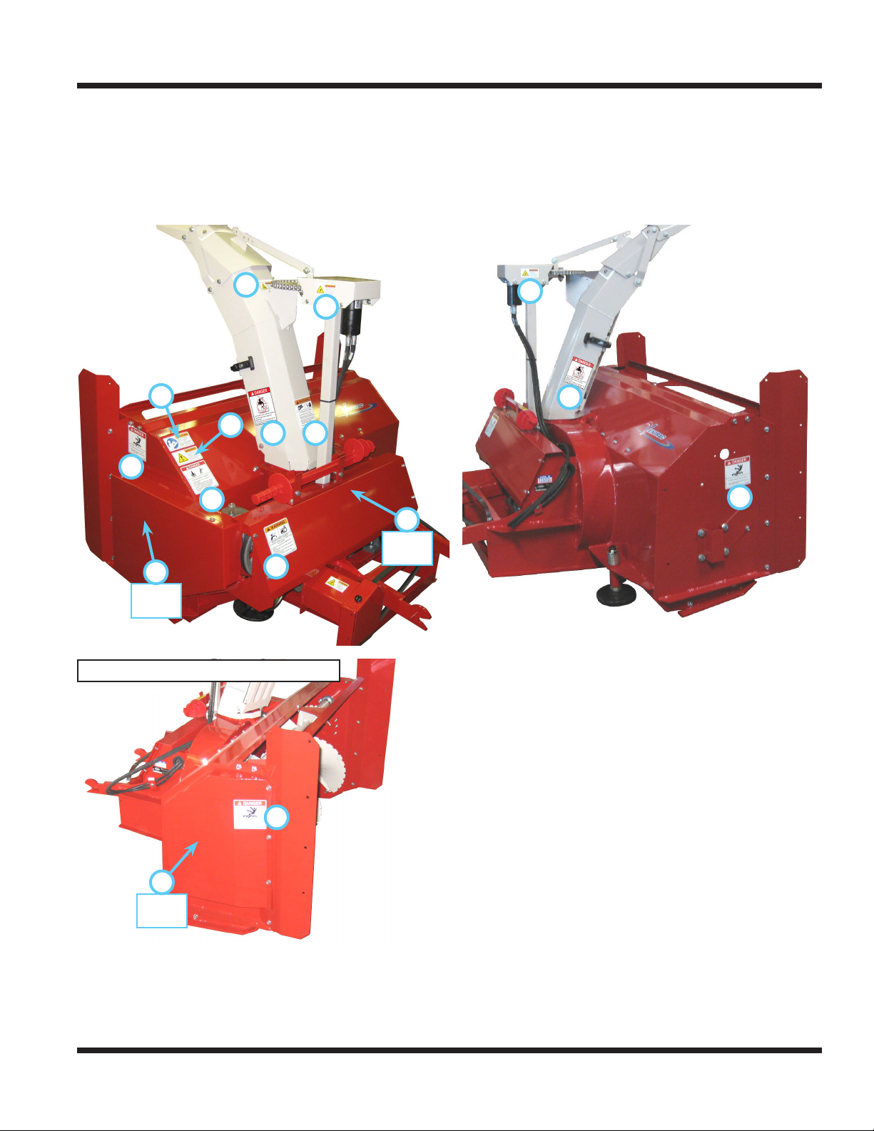
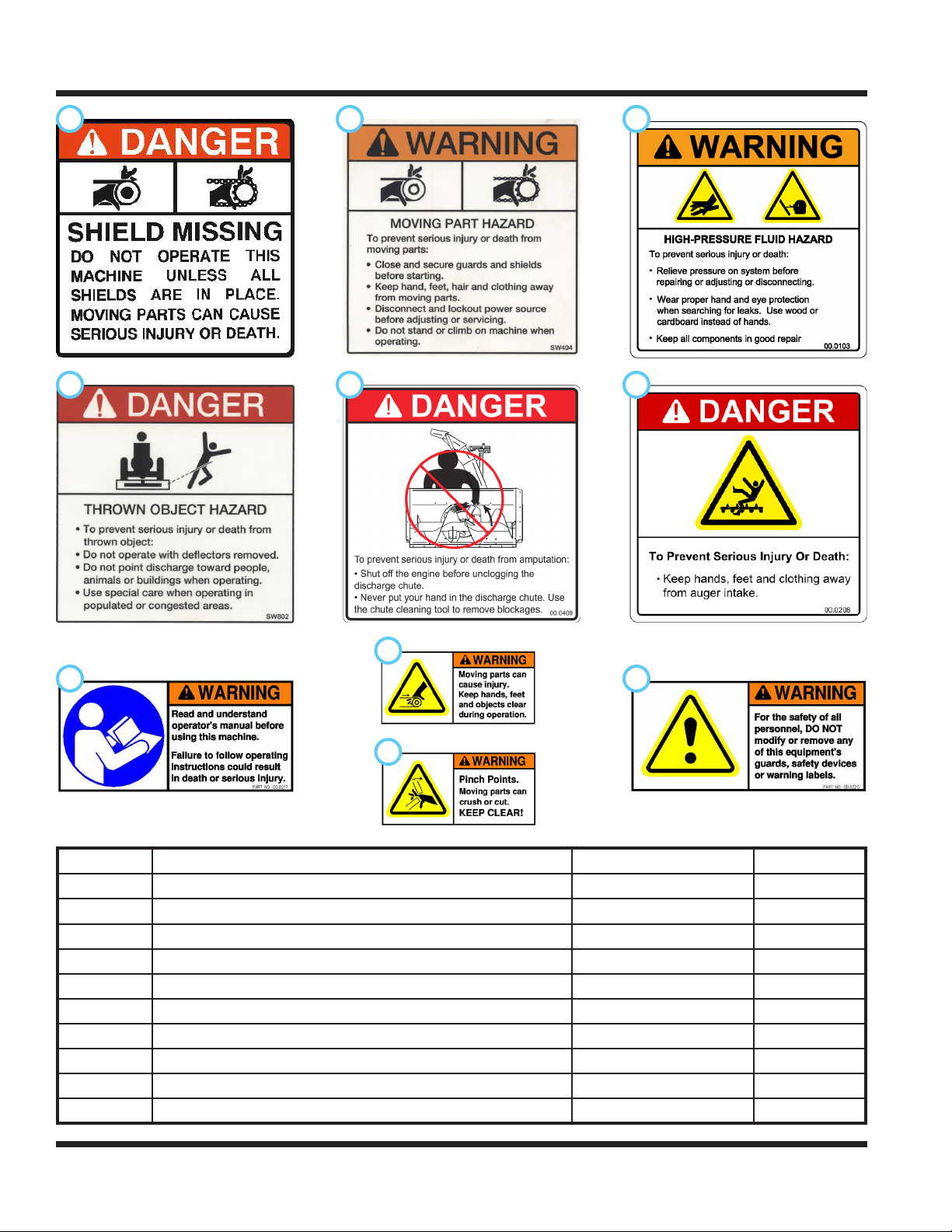
Safety Decals
The following safety decals must be maintained on your KX523 Snow Blower.
Keep all safety decals legible. Remove all grease dirt, and debris from safety decals and instructional
labels. If any decals are faded, illegible, or missing, contact your dealer promptly for replacements.
When new components are installed, be sure that current safety decals are afxed to the replacement
components.
I
G
H
J
F
D
A
Under
Shield
70.8072 Deep Snow Auger (if equipped)
C
E
B
G
E
F
A
Under
Shield
A
Under
Shield
F
Safety - 7
SAFETY
A
D F
B C
E
G
H
I
J
Decal Description Part Number Quantity
A Danger, Shield Missing 00.0062 2 (3)
B Warning - Moving Part Hazard 00.0101 1
C Warning, High Pressure Fluid 00.0103 1
D Danger, Thrown Object Hazard 00.0122 1
E Danger, Discharge Chute Safety 00.0409 2
F Danger, Auger Hazard 00.0208 2 (3)
G Warning, Moving Parts 00.0216 3
H Warning, Read Owner’s Manual 00.0217 1
I Warning, Pinch Point 00.0218 1
J Warning, General Safety 00.0220 1
Safety - 8
SAFETY
General Safety Procedures
for Ventrac Power Units, Attachments, & Accessories
Training Required
• The owner of this machine is solely responsible for properly training the operators.
• The owner/operator is solely responsible for the operation of this
machine and prevention of accidents or injuries occurring to him/herself, other people, or property.
• Do not allow operation or service by children or untrained personnel.
Local regulations may restrict the age of the operator.
• Before operating this machine, read the operator’s manual and understand its contents.
• If the operator of the machine cannot understand this manual, then it
is the responsibility of this machine’s owner to fully explain the material
within this manual to the operator.
• Learn and understand the use of all controls.
• Know how to stop the power unit and all attachments quickly in the event of an emergency.
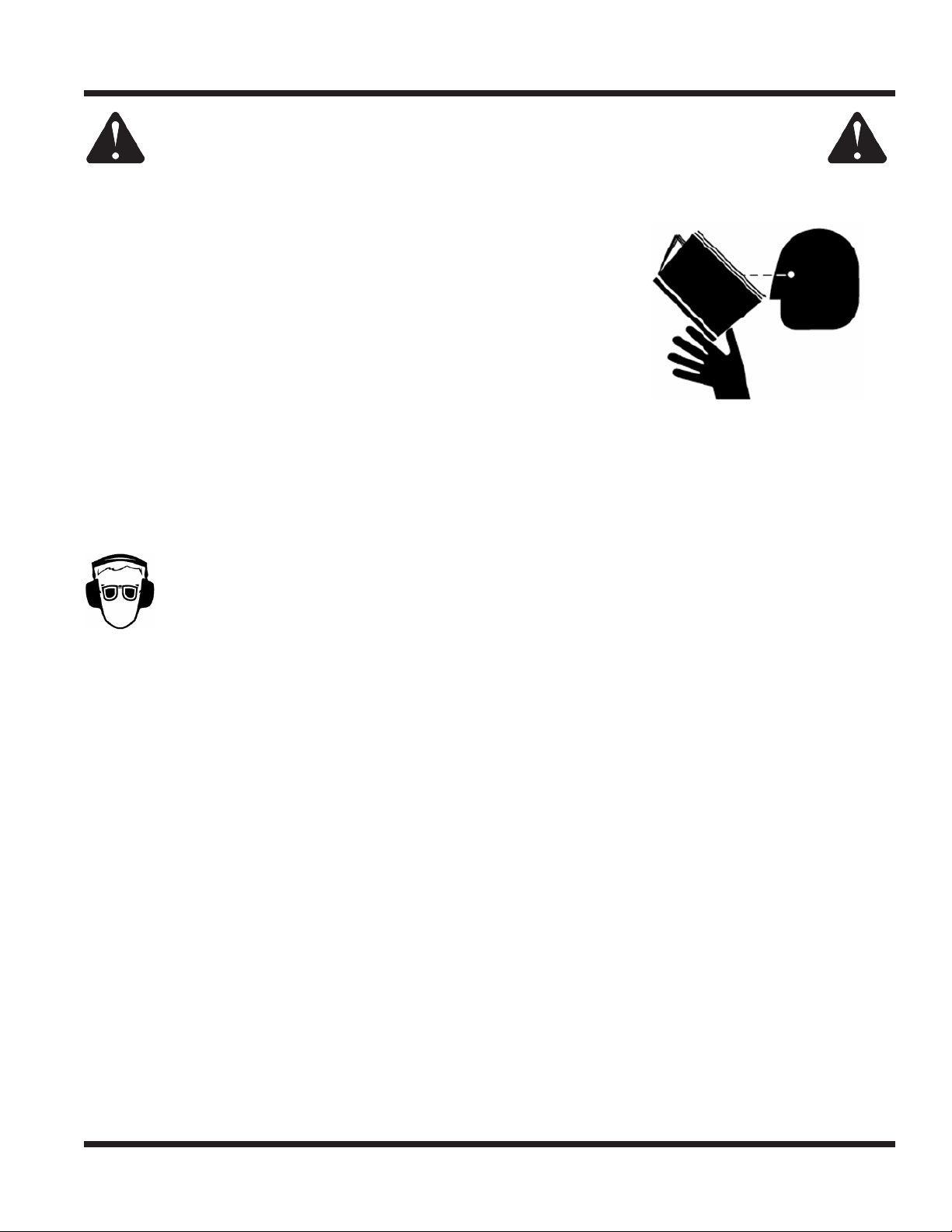
Personal Protective Equipment Requirements
It is the responsibility of the owner to be sure that the operators use the proper personal protective equipment while operating the machine. Required personal protective equipment includes, but is not limited to,
the following list.
• Wear a certied ear protection device to prevent loss of hearing.
• Prevent eye injury by wearing safety glasses while operating the machine.
• Closed toe shoes must be worn at all times.
• Long pants must be worn at all times.
• When operating in dusty conditions, it is recommended that a dust mask be worn.
Operation Safety
• Inspect machine before operation. Repair or replace any damaged, worn, or missing parts. Be sure
guards and shields are in proper working condition and are secured in place. Make all necessary
adjustments before operating machine.
• Some pictures in this manual may show shields or covers opened or removed in order to clearly illustrate
any instructions. Under no circumstance should the machine be operated without these devices in place.
• Alterations or modications to this machine can reduce safety and could cause damage to the machine.
Do not alter safety devices or operate with shields or covers removed.
• Before each use, verify that all controls function properly and inspect all safety devices. Do not operate
if controls or safety devices are not in proper working condition.
• Check parking brake function before operating. Repair or adjust parking brake if necessary.
• Observe and follow all safety decals.
• All controls are to be operated from the operator’s seat only.
• Always wear a seat belt if the machine has a roll cage/bar installed and in upright position.
• Ensure the attachment or accessory is locked or fastened securely to the power unit before operating.
• Ensure that all bystanders are clear of the power unit and attachment before operating. Stop machine if
someone enters your work area.
• Always be alert to what is happening around you, but do not lose focus on the task you are performing.
Always look in the direction the machine is moving.
• Look behind and down before backing up to be sure of a clear path.
• If you hit an object, stop and inspect the machine. Make all necessary repairs before operating machine again.
• Stop operation immediately at any sign of equipment failure. An unusual noise can be a warning of equipment
failure or a sign that maintenance is required. Make all necessary repairs before operating machine again.
Safety - 9
SAFETY
General Safety Procedures
for Ventrac Power Units, Attachments, & Accessories
Operation Safety (continued)Operation Safety (continued)
• If equipped with a high/low range feature, never shift between high and low range while on a slope.
Always move the machine to level ground and engage the parking brake before shifting range.
• Do not leave machine unattended while it is running.
• Always park the machine on level ground.
• Always shut off engine when connecting attachment drive belt to the power unit.
• Never leave the operator’s seat without lowering the attachment to the ground, setting the parking
brake, shutting off the engine, and removing the ignition key. Make sure all moving parts have come to
a complete stop before dismounting.
• Never leave equipment unattended without lowering the attachment to the ground, setting the parking
brake, shutting off the engine, and removing the ignition key.
• Only operate in well-lit conditions.
• Do not operate when there is a risk of lightning.
• Never direct the discharge of any attachment in the direction of people, buildings, animals, vehicles, or
other objects of value.
• Never discharge material against a wall or obstruction. Material may ricochet back towards the operator.
• Use extra caution when approaching blind corners, shrubs, trees, or other objects that may obscure vision.
• Do not run the engine in a building without adequate ventilation.
• Do not touch the engine or the mufer while the engine is running or immediately after stopping the engine.
These areas may be hot enough to cause a burn.
• Do not change the engine governor settings or over-speed the engine. Operating engine at excessive speed
may increase the hazard of personal injury.
• To reduce the hazard of re, keep the battery compartment, engine, and mufer areas free of grass, leaves,
and excessive grease.
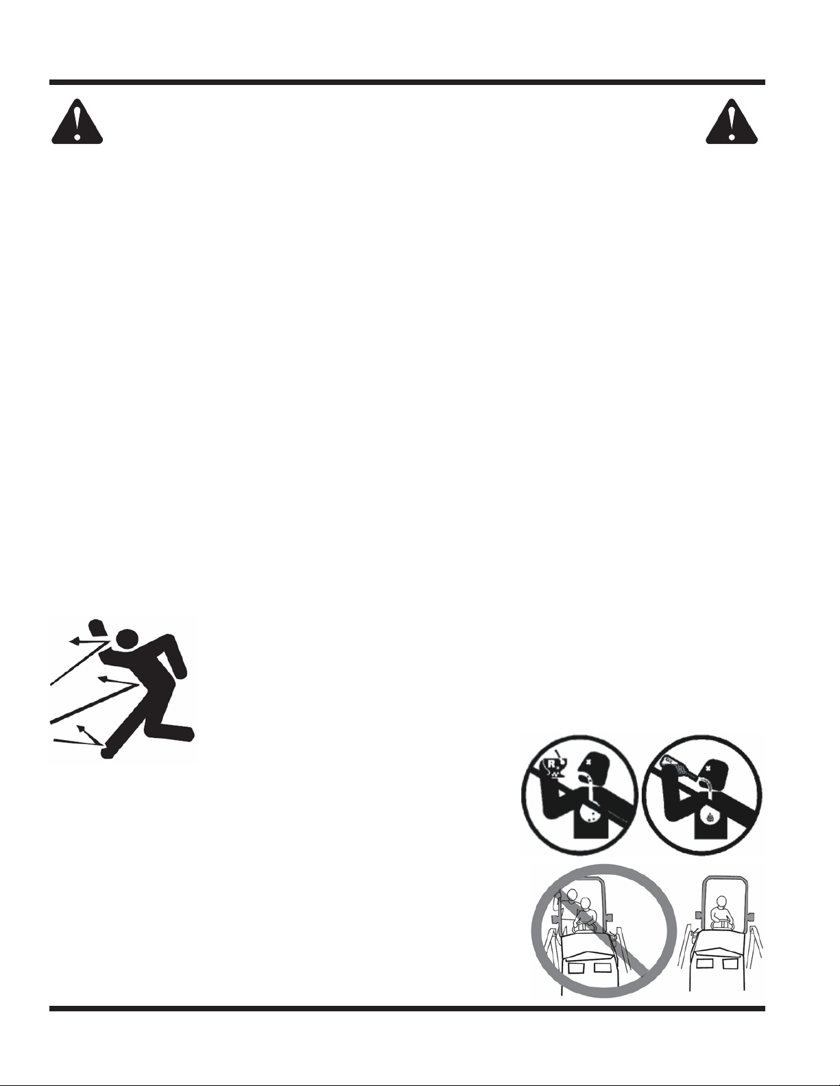
Preventing Accidents
• Clear working area of objects that might be hit or thrown from machine.
• Keep people and pets out of mowing area.
• Know the work area well before operation. Do not operate where traction or
stability is questionable.
• Reduce speed when you are operating over rough ground.
• Equipment can cause serious injury and/or death when improperly used.
Before operating, know and understand
the operation and safety of the power
unit and the attachment being used.
• Do not operate machine if you are not in good physical and
mental health, if you will be distracted by personal devices, or are
under the inuence of any substance which might impair decision, dexterity, or judgment.
• Children are attracted to machine activity. Be aware of children
and do not allow them in the working area. Turn off the machine if
a child enters the work area.
Keep Riders Off
• Only allow the operator on the power unit. Keep riders off.
• Never allow riders on any attachment or accessory.
Safety - 10
SAFETY
General Safety Procedures
for Ventrac Power Units, Attachments, & Accessories
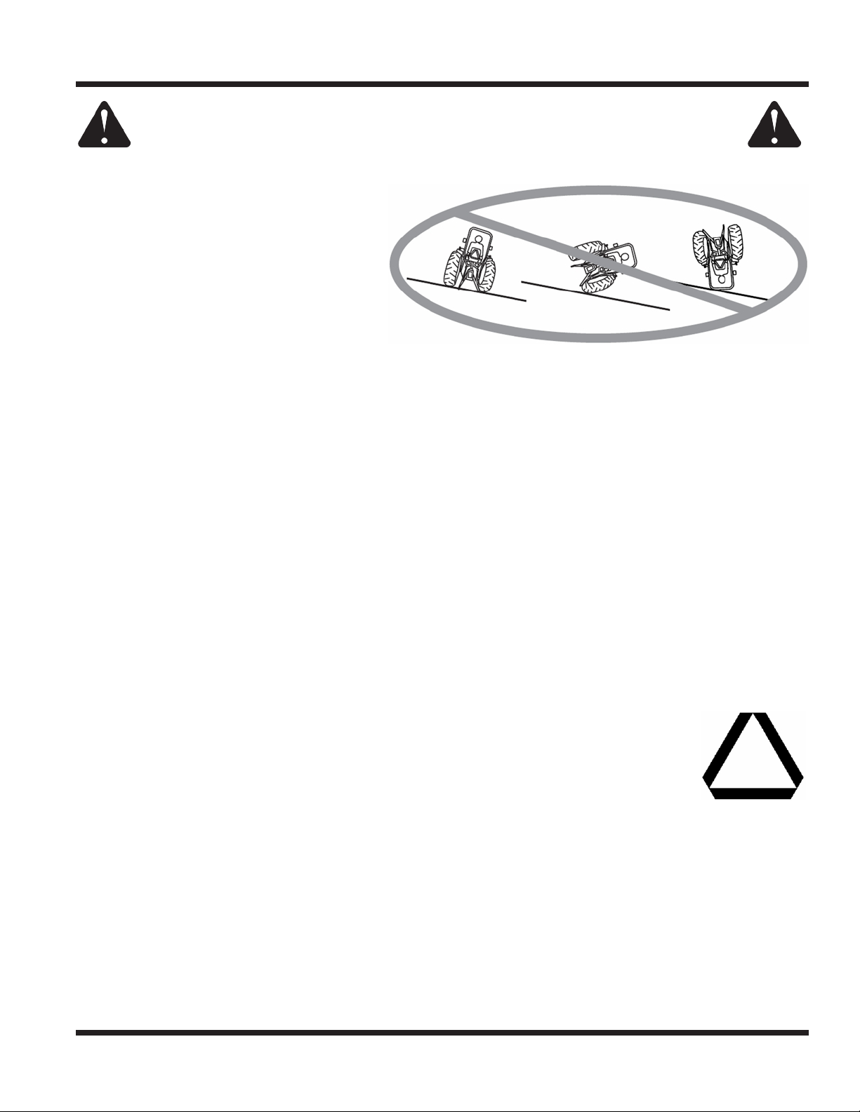
Operating On Slopes
• Slopes can cause loss-of-control and
tip-over accidents, which can result in
severe injury or death. Be familiar with the
emergency parking brake, along with the
power unit controls and their functions.
• If power unit is equipped with a fold down
roll bar, it must be locked in the upright
position when operating on any slope.
• Use low range (if equipped) when operating
on slopes greater than 15 degrees.
• Do not stop or start suddenly when operating on slopes.
• Never shift between high and low range while on a slope. Always move the power unit to level ground
and engage the parking brake before shifting range or placing the power unit in neutral.
• Variables such as wet surface and loose ground will reduce the degree of safety. Do not drive where
machine could lose traction or tip over.
• Keep alert for hidden hazards in the terrain.
• Stay away from drop-offs, ditches, and embankments.
• Sharp turns should be avoided when operating on slopes.
• Pulling loads on hills decreases safety. It is the responsibility of the owner/operator to determine loads
that can safely be controlled on slopes.
• Transport machine with attachment lowered or close to the ground to improve stability.
• While operating on slopes, drive in an up and down direction when possible. If turning is necessary
while driving across slopes, reduce speed and turn slowly in the downhill direction.
• Assure a sufcient supply of fuel for continuous operation. A minimum of one-half tank of fuel is recommended.
Roadway Safety
• Operate with safety lights when operating on or near roadways.
• Obey all state and local laws concerning operation on roadways.
• Slow down and be careful of trafc when operating near or crossing roadways. Stop before crossing
roads or sidewalks. Use care when approaching areas or objects that may obscure vision.
• If there is doubt of safety conditions, discontinue machine operation until a time when
operation can be performed safely.
• When operating near or on roadways, have a Slow Moving Vehicle Emblem clearly
displayed.
Truck Or Trailer Transport
• Use care when loading or unloading machine into a truck or trailer.
• Use full width ramps for loading machine into a truck or trailer.
• The parking brake is not sufcient to lock the machine during transport. Always secure the power unit
and/or attachment to the transporting vehicle securely using straps, chains, cable, or ropes. Both front
and rear straps should be directed down and outward from the machine.
• Shut off fuel supply to power unit during transport on truck or trailer.
• If equipped, turn the battery disconnect switch to the Off position to shut off electrical power.
Safety - 11

SAFETY
General Safety Procedures
for Ventrac Power Units, Attachments, & Accessories
Maintenance
• Keep all safety decals legible. Remove all grease dirt, and debris from safety decals and instructional labels.
• If any decals are faded, illegible, or missing, contact your dealer promptly for replacements.
• When new components are installed, be sure that current safety decals are afxed to the replacement
components.
• If any component requires replacement, use only original Ventrac replacement parts.
• Always turn the battery disconnect to the Off position or disconnect the battery before performing any
repairs. Disconnect the negative terminal rst and the positive terminal last. Reconnect the positive
terminal rst and the negative terminal last.
• Keep all bolts, nuts, screws, and other fasteners properly tightened.
• Always lower the attachment to the ground, engage parking brake, shut off engine, and remove the
ignition key. Make sure all moving parts have come to a complete stop before cleaning, inspection,
adjusting or repairing.
• If the power unit, attachment, or accessory requires repairs or adjustments not instructed in the operator’s
manual, the power unit, attachment, or accessory must be taken to an authorized Ventrac dealer for service.
• Never perform maintenance on the power unit and/or attachment if someone is sitting in the operator’s seat.
• Always use protective glasses when handling the battery.
• Check all fuel lines for tightness and wear on a regular basis. Tighten or repair them as needed.
• To reduce the hazard of re, keep the battery compartment, engine, and mufer areas free of grass,
leaves, and excessive grease.
• Do not touch the engine, the mufer, or other exhaust components while the engine is running or imme-
diately after stopping the engine. These areas may be hot enough to cause a burn.
• Allow the engine to cool before storing and do not store near an open ame.
• Do not change the engine governor settings or over-speed the engine. Operating engine at excessive
speed may increase the hazard of personal injury.
• Springs may contain stored energy. Use caution when disengaging or removing springs and/or spring
loaded components.
• An obstruction or blockage in a drive system or moving/rotating parts may cause a buildup of stored
energy. When the obstruction or blockage is removed, the drive system or moving/rotating parts may
move suddenly. Do not attempt to remove an obstruction or blockage with your hands. Keep hands,
feet, and clothing away from all power-driven parts.
• Dispose of all uids in accordance with local laws.
Fuel Safety
• To avoid personal injury or property damage, use extreme care in handling gasoline. Gaso-
line is extremely ammable and the vapors are explosive.
• Do not refuel machine while smoking or at a location near ames or sparks.
• Always refuel the machine outdoors.
• Do not store machine or fuel container indoors where fumes or fuel can reach an open
ame, spark, or pilot light.
• Only store fuel in an approved container. Keep out of reach of children.
• Never ll containers inside a vehicle or on a truck or trailer bed with a plastic liner. Always place containers
on the ground away from your vehicle before lling.
• Remove machine from the truck or trailer and refuel it on the ground. If this is not possible, refuel the
machine using a portable container, rather than from a fuel dispenser nozzle.
• Never remove fuel cap or add fuel with the engine running. Allow engine to cool before refueling.
• Never remove fuel cap while on a slope. Only remove when parked on a level surface.
• Replace all fuel tank and container caps securely.
Safety - 12

SAFETY
General Safety Procedures
for Ventrac Power Units, Attachments, & Accessories
Fuel Safety (continued)
• Do not overll fuel tank. Only ll to bottom of fuel neck, do not ll fuel neck full. Overlling of fuel tank could
result in engine ooding, fuel leakage from the tank, and/or damage to the emissions control system.
• If fuel is spilled, do not attempt to start the engine. Move the power unit away from the fuel spill and
avoid creating any source of ignition until fuel vapors have dissipated.
• If the fuel tank must be drained, it should be drained outdoors into an approved container.
• Dispose of all uids in accordance with local laws.
• Check all fuel lines for tightness and wear on a regular basis. Tighten or repair them as needed.
• The fuel system is equipped with a shut-off valve. Shut off the fuel when transporting the machine to
and from the job, when parking the machine indoors, or when servicing the fuel system.
Hydraulic Safety
• Make sure all hydraulic connections are tight and all hydraulic hoses and tubes are in good condition.
Repair any leaks and replace any damaged or deteriorated hoses or tubes before starting the machine.
• Hydraulic leaks can occur under high pressure. Hydraulic leaks require special care and attention.
• Use a piece of cardboard and a magnifying glass to locate sus-
pected hydraulic leaks.
• Keep body and hands away from pinhole leaks
or nozzles that eject high pressure hydraulic uid.
Hydraulic uid escaping under high pressure can
penetrate the skin causing serious injury, leading to
severe complications and/or secondary infections
if left untreated. If hydraulic uid is injected into the
skin, seek immediate medical attention no matter
how minor the injury appears.
• Hydraulic system may contain stored energy. Before performing maintenance or repairs on the hydraulic
system, remove attachments, engage parking brake, disengage weight transfer system (if equipped), shut
off engine, and remove ignition key. To relieve pressure on the auxiliary hydraulic system, shut off the power
unit engine and move the secondary S.D.L.A. lever left and right before disconnecting the auxiliary hydraulic
quick couplers.
• Dispose of all uids in accordance with local laws.
Safety - 13

SAFETY
KX523 Snow Blower Safety Procedures
• This snow blower is capable of amputating hands and feet and throwing objects. Failure to observe the
following safety instructions could result in serious injury.
• Read and understand the KX523 snow blower operator’s manual before operating the snow blower.
• Before making repairs or adjustments to the snow blower, engage the power unit’s parking brake, lower
the snow blower to the ground, shut off the power unit’s engine, and remove the ignition key.
• Always block up the snow blower securely when adjusting the skid shoes.
• The snow blower housing is open in the front due to its functionality, thus exposing the auger. When operating, EXTREME care should be used when approaching a stationary object such as a tree or a pole.
• Do not put hands or feet near or under rotating parts. Keep clear of the discharge opening at all times.
• Never direct the snow blower discharge chute in the direction of people, buildings, animals, vehicles, or
other objects of value. Debris can be thrown from the chute causing damage, serious injury, or death.
• Never operate the snow blower when people are in the area. Frozen snow, ice, gravel, and other
objects can be thrown at lethal velocity.
• Operators should be familiar with the area they are clearing and make preparations ahead of time.
Place guide stakes appropriately and remove stones, markers, or other debris that may be hidden after
a snowfall. Curbs, offsets, steps, man hole covers, broken or raised pavement, etc. should be noted.
Operators should map areas to be cleared before the winter season so they can review potential hazards prior to clearing snow in the area.
• If an area is to be cleared that is unfamiliar to the operator, travel slowly and use EXTREME CAUTION.
Inquire of anyone who might know of potential hazards.
• Discharge snow with the wind direction as much as possible. Discharging into the wind reduces blowing
distance and visibility.
• The operator should never proceed if visibility is poor. If the tractor is equipped with a cab, the windshield must be kept clean.
• Use caution when operating around objects that can obstruct your vision.
• Never travel at speeds that would cause injury to the operator or damage to the machine if the machine
were to be stopped suddenly by an unseen, immovable object.
• Never operate at high transport speeds on slippery surfaces.
• No one other than the operator should ever attempt to clear the discharge opening in the event of a
blockage. Lower the snow blower to the ground, set the power unit’s parking brake, shut off the power
unit’s engine, and remove the ignition key before any attempt is made to clear the blockage.
• Hand contact with the rotating fan inside the discharge chute is the most common cause of injury
associated with snow blowers. Never use your hand to clean out the discharge chute. Use the provided
chute cleaning tool to clear blockages.
• If the chute guard has been opened to clear a blockage, it must be closed and fastened before resuming operation.
• Do not operate the equipment without wearing adequate winter garments. Avoid loose tting clothing
that can get caught in moving parts. Wear footwear that will improve footing on slippery surfaces.
• Shut off the power unit’s PTO when not blowing snow.
• Always shut off the power unit’s PTO and engage the parking brake before dismounting to change the
angle of the discharge chute deector.
• Attachment hydraulic system may contain stored energy. Before performing maintenance or repairs on
the hydraulic system, the attachment’s auxiliary hydraulic hoses must be disconnected from the power
unit. Lower the attachment to the ground, shut off power unit engine, move the secondary S.D.L.A. lever
left and right to relieve auxiliary hydraulic pressure, and disconnect the auxiliary hydraulic quick couplers.
Safety - 14
OPERATIONAL CONTROLS
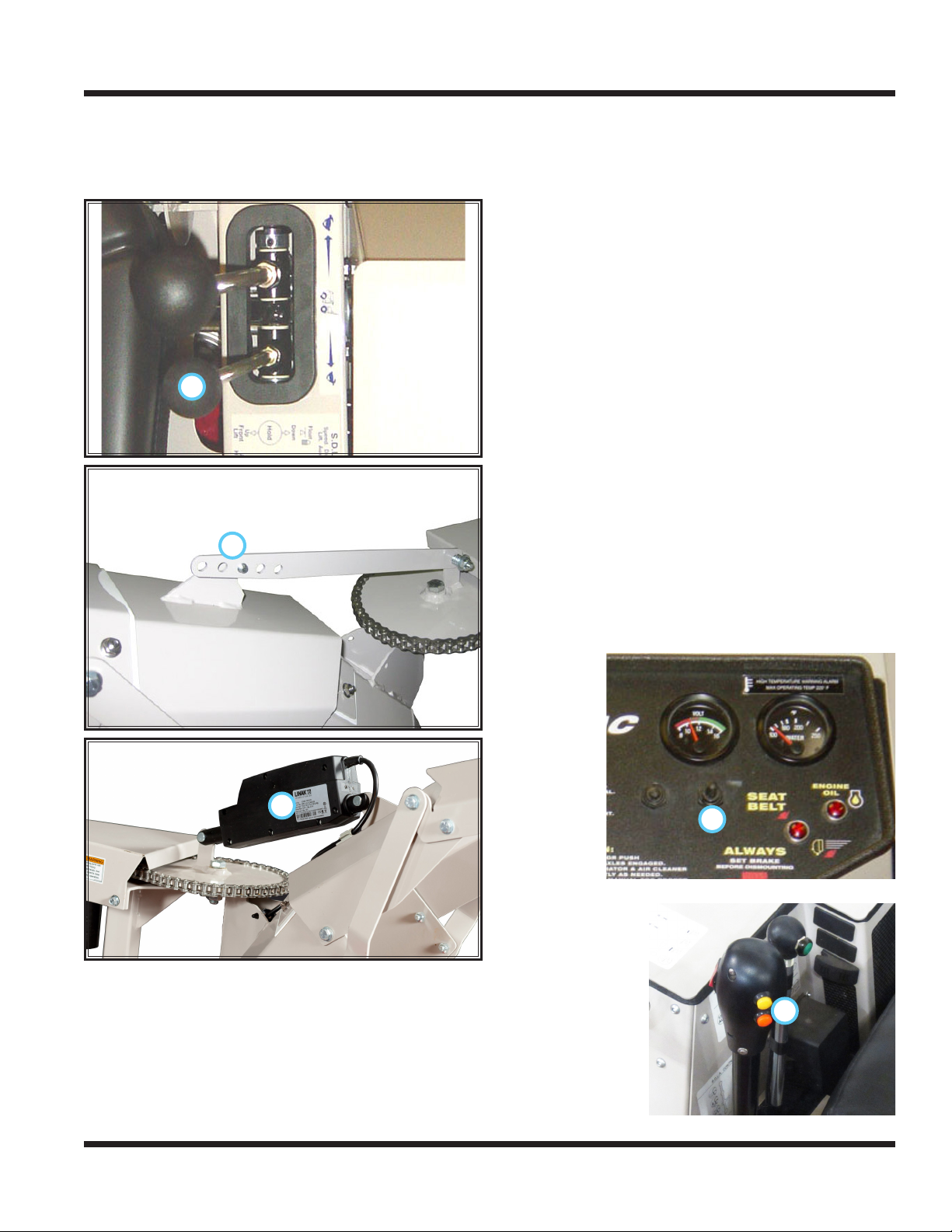
Operational Control Locations
Use the following images to help identify the locations
of operational controls. The letter next to each control
can be referenced to the list that follows these images.
A
B
A. Discharge Chute Rotation
(Secondary S.D.L.A. Lever)
B. Discharge Chute Adjustment Link
C. Optional Discharge Chute Deector
Actuator Control
Discharge Chute Rotation (A)
(Secondary S.D.L.A. Lever)
The secondary S.D.L.A. lever on the power unit controls the hydraulic rotation of the discharge chute.
The discharge chute can be angled from left to right
(180 degrees of rotation) to discharge snow in the
desired direction.
Discharge Chute Adjustment Link (B)
The discharge chute adjustment link controls the
angle of the discharge chute deector. The angle of
the discharge chute deector determines the dis-
tance that snow is thrown.
Optional Discharge Chute Deector
Actuator Control (C)
This optional actuator replaces the discharge chute
adjustment link on the snow blower. It couples with
a 12 volt switch on the power unit, allowing the
operator to control the angle of the discharge chute
deector from the operator’s seat.
The actuator D
is controlled
with an
optional dash
mounted
momentary
on toggle
C
switch (D) on
KT4100 and
KT4200
models.
The actuator is E
controlled by
momentary on
switches (E) on the
optional 12V front
SDLA handle on
KN4500 models.
Operation - 15
 Loading...