

Ventrac HQ680 Owner's And Operator's Manual
OWNER/OPERATOR’S
MAN UAL & PARTS LIST
Tough-Cut Mower
HQ680 (Serial # 1001-1901)
Re vised 05/17/18
09.10014
Orrville, OH
www.ventrac.com
TO THE OWNER
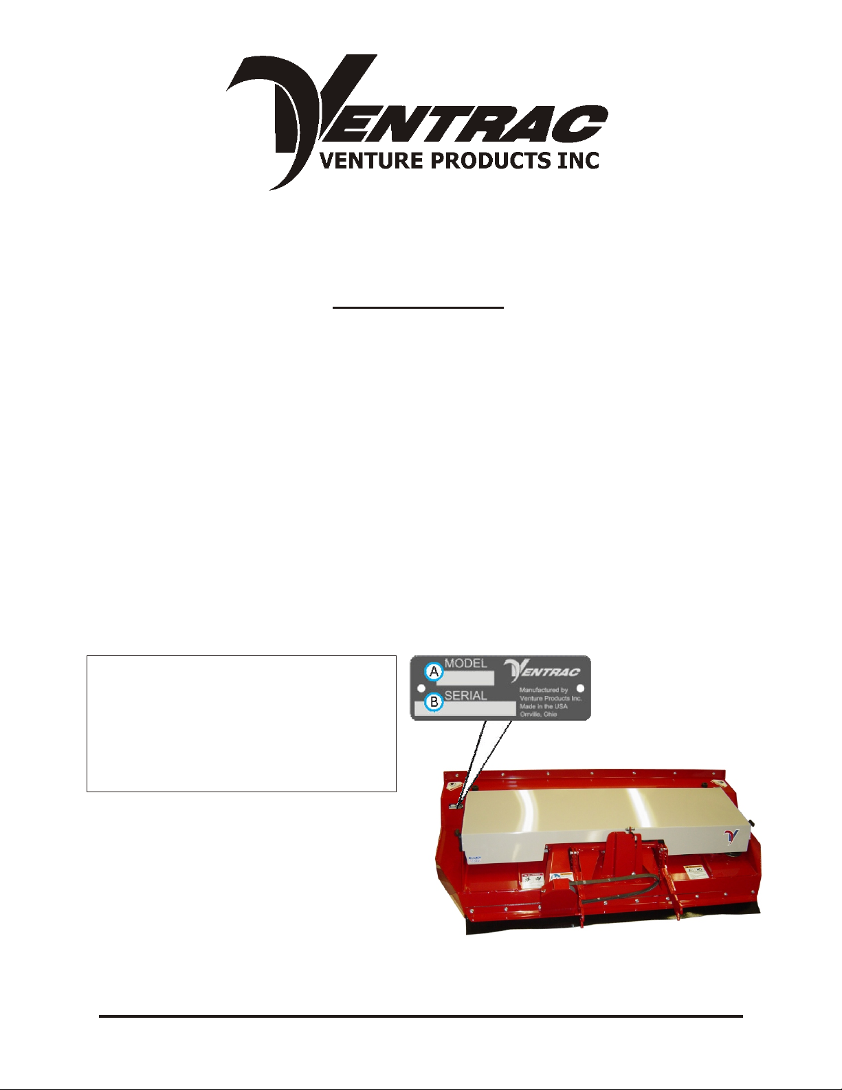
Prod uct Iden ti fi ca tion
If you need to con tact an Au tho rized Ventrac Dealer for in for ma tion on ser vic ing your prod uct,
al ways pro vide the Prod uct Model and Se rial num bers.
Please fill in the fol low ing in for ma tion for fu ture ref er ence. See pic ture be low to find the
lo ca tion of the iden ti fi ca tion num ber. Re cord them in the spaces pro vided be low.
Date of Pur chase: Month _________________ Day ___________ Year ___________________
Dealer: _______________________________________________________________________
Dealer Ad dress: ________________________________________________________________
________________________________________________________________
Dealer Phone Num ber: __________________________________________________________
Dealer FAX Num ber: ____________________________________________________________
Model # (A): _______________________
Se rial # (B): ________________________
Af fix Part/Se rial Num ber la bel here
Ven ture Prod ucts Inc. re serves the right to make changes
in de sign or spec i fi ca tions with out ob li ga tion to make like
changes on pre vi ously man u fac tured prod ucts.
ii

TA BLE OF CON TENTS
IN TRO DUC TION Sec tion A
De scrip tion ....................................A-1
Spec i fi ca tions ...................................A-2
SAFETY Sec tion B
Safety Sym bols ..................................B-1
De cals .......................................B-2
Gen eral Safety Pro ce dures ............................B-3
Safety Op er a tion & Tech niques ..........................B-4
OP ER A TION Sec tion C
Ini tial Jack Stand In stal la tion ...........................C-1
At tach ing .....................................C-2
De tach ing .....................................C-2
Ini tial Set ting of Hitch Pins ............................C-2
Gen eral Op er at ing Tech niques & Tips ....................C-3 & 4
Duals .......................................C-5
Swivel Wheel Cut ting Height Guide ........................C-5
MAIN TE NANCE Sec tion D
Lu bri ca tion ....................................D-1
Re moval & Re in stal la tion of Blades ........................D-2
Sharpening Blades ................................D-2
Stor age ......................................D-2
Belt Re place ment .................................D-3
Main Deck Belt Re place ment ...........................D-3
Right Belt Re place ment ..............................D-3
Drive Belt Re place ment ..............................D-3
PARTS & IL LUS TRATED DRAW INGS Sec tion E
Main Deck ...................................E-1 & 2
Hitch Arms ..................................E-3 & 4
Spin dles (Se rial # AA1007-AA1275) ........................E-5 & 6
Spin dles (Se rial # AB1276-AC1635) ...........................E-5b & 6b
Spin dles (Se rial # AD1636-) ................................E-5c & 6c
Cover Shield .................................E-7 & 8
PARTS/OP TIONS Sec tion F
70.8054 Swivel Wheel Kit ...........................F-1 & 2
WAR RANTY
iii

IN TRO DUC TION
Prod uct De scrip tion
The new VENTRAC Model HQ680 “Tough-Cut” rotary mower features an enclosed
deck designed for field and brush mowing. The broad, belted, high intake front creates
an “attack” on tall grasses and brush before it is leveled. The straight front deck design
provides structural strength and a uniform performance in tall vegetation.
Two cast-iron gauge wheels with 5/8th inch rubber coating, roller bearings and grease
zerks help to gauge the mowing depth and reduce scalping. They can be adjusted to
three cut heights.
The VENTRAC “Quick Attach” makes the “Tough-Cut” a quick option among the
VENTRAC’s (4000 series) many attachments. Variables in tractor hitch heights can be
accommodated by properly positioning the hitch pins in the deck frame. Easy servicing
is provided by the hinged and removable cover and deck tilt to access the underside
and blades.
Power consumption is always relative to numerous factors but generally the
“Tough-Cut” operates easily and does not necessarily require full engine rpms.
Proper service, maintenance and safe operation of the HQ680 “Tough-Cut” will provide
great results for field and brush mowing.
Ventrac HQ680 Spec i fi ca tions
Over all Width ...........................68 inches
Length ...............................46 inches
Height ...............................18 inches
Weight ..............................325 pounds
Blades ....................................3
6” gauge wheels ..............................2
Cut ting height ad just ments ................3”, 3-5/8”, 4-1/4”
These spec i fi ca tions are sub ject to change with out no tice.
A-1
SAFETY
AT TEN TION:
This symbol identifies potential health and
safety hazards. It marks safety precautions.
Your safety and the safety of others is involved.
SIG NAL WORD DEF I NI TIONS
Indicates an imminently hazardous
situation which, if not avoided, will result in
death or serious injury. This signal word is
limited to the most extreme cases.
Indicates a potentially hazardous situation
which, if not avoided, could result in death
or serious injury.
Indicates a potentially hazardous situation
which, if not avoided, may result in minor
or moderate injury and/or property
damage. It may also be used to alert
against unsafe practices.
B-1
SAFETY
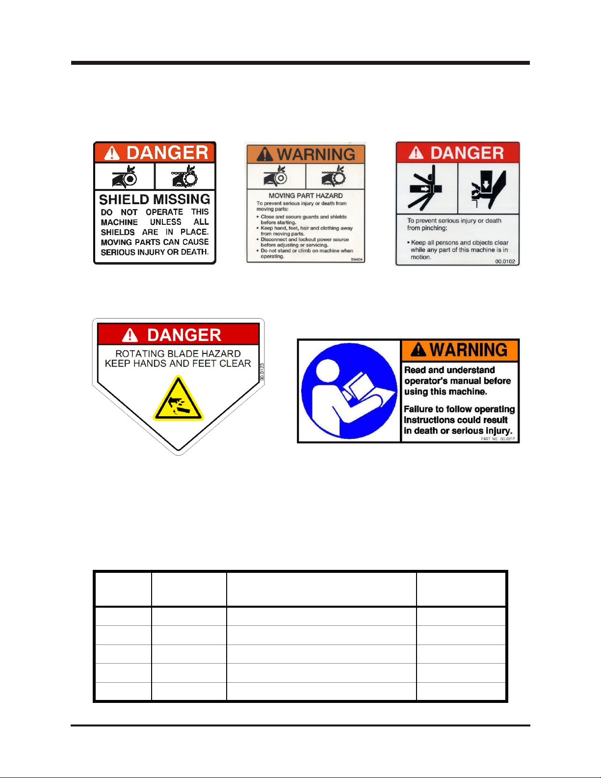
The fol low ing de cals must be main tained on your Ventrac At tach ment. If any de cals are faded or miss ing, con tact your dealer promptly for re place ments.
A
D
B
C
E
De cal
A
B
C
D
E
Page &
De scrip tion Part Num ber
Lo ca tion
E-1, #28 Dan ger - Shield Missing 00.0062
E-1, #20 Warn ing - Mov ing Part Haz ard 00.0101
E-1, #27 Dan ger - Pinch ing Haz ard 00.0102
E-1, #15 (2) Keep Hands and Feet Away 00.0123
E-3, # 35 Warn ing - Read Owner's Manual 00.0217
B-2

SAFETY
Gen eral Safety Pro ce dures
for Ventrac Trac tors, At tach ments, & Ac ces sories
Read and understand the operator’s manual before operating this equipment.
Observe and follow all safety decals.
DO NOT let children or any untrained person operate the tractor or attachment.
Make sure that all operators of this equipment are thoroughly trained in using it
safely.
Never allow additional riders on the tractor or attachments.
DO NOT operate tractor or attachments if you are under the influence of alcohol,
drugs, medication that may impair judgment or cause drowsiness, or if you are not
feeling well.
Operate all controls from the operators seat only.
Before operating equipment, make sure all shields are in place and fastened.
Ensure the attachment or accessory is locked or fastened securely to the tractor
(power unit) before operating. See tractor manual for locking procedure.
Ensure that all bystanders are clear of the tractor and attachment before operating.
Be especially careful and observant if other people are present. Never assume that
bystanders will remain where you last saw them.
Always look in the direction the tractor is moving.
Never direct the discharge of any attachment in the direction of people, animals,
buildings, vehicles, or objects of value.
Immediately stop at any sign of equipment failure and correct the problem before
continuing to operate. An unusual noise can be a warning of equipment failure.
Before adjusting, cleaning, lubricating, or changing parts on the tractor or attachment,
engage the parking brake, lower the attachment to the ground, stop the engine, and
remove the ignition key.
To prevent the risk of uncontrolled equipment movement on tractors equipped with 2
speed axles, always shift the transaxle range with the power unit stationary on level
ground and with the parking brake engaged.
If equipment is to be left unattended, engage the parking brake, lower the attachment
to the ground, stop the engine, and remove the ignition key.
B-3

SAFETY
HQ680 Safety Pro ce dures
Before making any repairs or adjustments, lower
attachment to the ground, set parking brake, shut
the engine off, and remove the key.
Read and understand the operator’s manual before
operating this equipment.
• Do not mow in areas that contain stones, sticks or other foreign objects that may be
thrown from the mower.
• Rotating Blades Are Dangerous
• Stop the machine if a person enters the mowing area.
• Be alert at all times; drive carefully because people and especially CHILDREN can
move quickly into the mowing area.
• Shut off PTO when you are not mowing.
• Use extra care when you come to shrubs, trees, or objects that may block your vision.
• Never mow toward a person or object of value.
B-4
OP ER A TION
Setup In struc tions for the HQ680 Tough Cut Mower
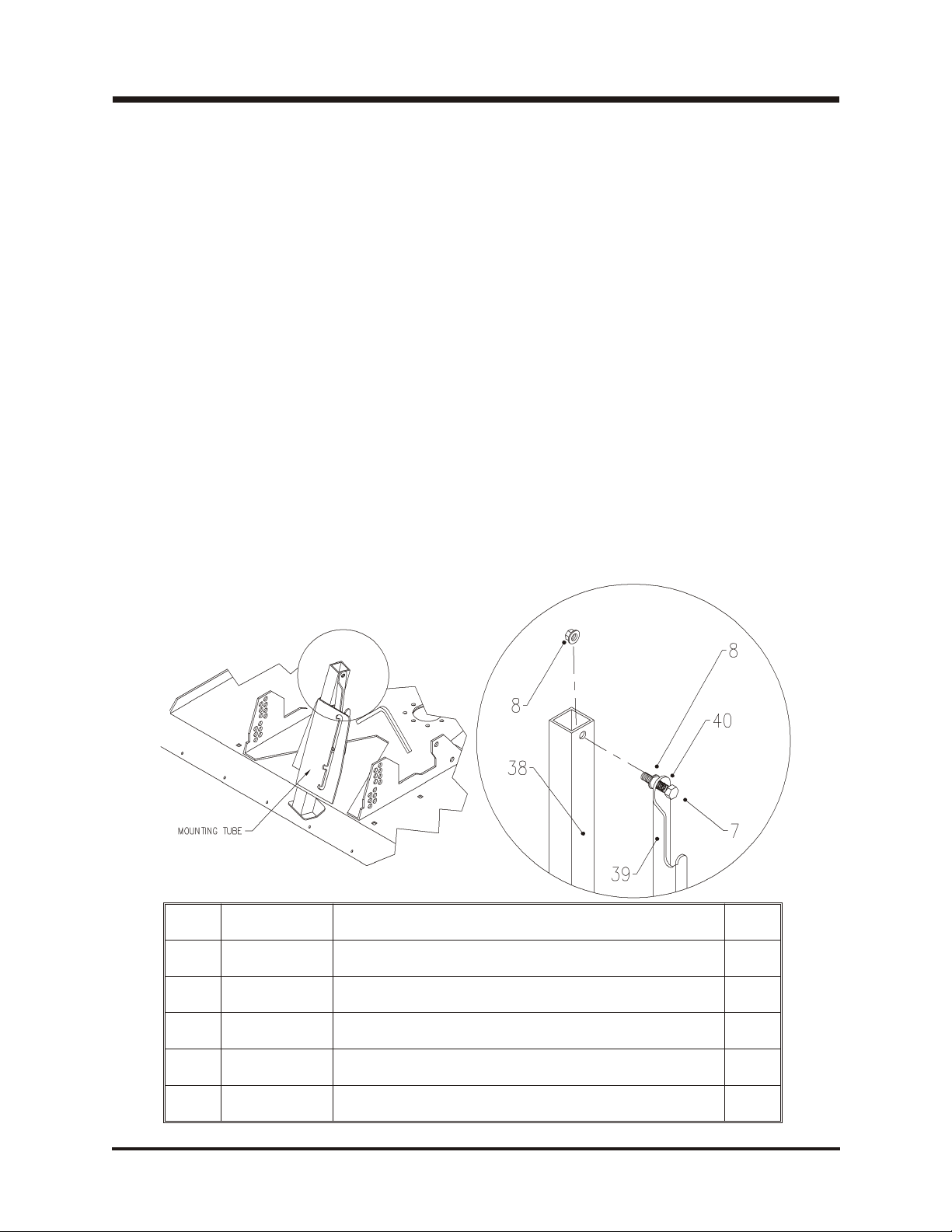
Jack Stand In stal la tion:
To install the jack stand into the mounting tube as shown below, raise the back of the
mower far enough to insert the stand in the tube. This can be accomplished be setting
the mower crosswise on the crate or using a lifting device. Remember, whatever
method is used keep safety in mind and use common safety procedures such as using
stands, blocking, or a restraining device.
Remove the tyton tie which holds the latch handle to the mounting tube. Insert the jack
stand into the mounting tube as shown in fig.1. Ensure that the bolt hole in the top of
the jack stand faces to the right side of the deck. (Refer to the parts drawing on pg. E-1
for further reference). Remove the outer nut from the latch handle, insert the bolt
through the jack stand and replace the nut. Adjust spring tension as tight as possible,
while still allowing the jack stand latch to operate freely in and out of the notch when
raising or lowering the jack stand.
When mowing or transporting, the jack stand should always be in the very top setting.
(Refer to pg. C-2). For tilting the deck up, move the jack stand to the middle setting
(refer to pg. C-4). This will allow for ground clearance as well as to ensure the jack
stand does not hit the front of the tractor. To disconnect the deck from the tractor, lower
the stand to the lowest setting prior to removing the mower from the tractor. (Refer to
pg. C-2).
REF PART # DE SCRIP TION QTY
7
8
38
39
40
90.0612 3/8-16 X 1-1/2 BOLT 1
99.SF06 3/8-16 FLANGE NUT 2
62.1011 JACK STAND 1
64.1114 JACK STAND LATCH 1
41.0039 9/16 OD X 5/8 COM PRES SION SPRING 1
C-1

OP ER A TION
OP ER ATING IN STRUC TIONS
Attaching:
1. Drive the tractor slowly forward into the mating arms on the mower. Align the hitch
arms to complete the engagement.
2. Once completely engaged, close the front hitch latch.
3. Stop the tractor engine.
4. Place attachment belt over the outside groove of the PTO drive pulley on the tractor.
5. Engage the PTO spring tension lever.
6. Lift up jack stand.
7. If your VENTRAC 4000 series has a traction transfer system, engage according to
instructions in tractor owner’s manual.
8. Make sure the tractor has enough counterweight installed to keep the rear tires on
the ground at all times. The amount of counterweight needed will depend on the
terrain, slopes, and the manner in which the tractor is operated.
Detaching:
Park the tractor on a level surface and set the parking brake.
1. Raise the deck all the way up.
2. Stop the tractor engine.
3. Release the PTO lever slowly.
4. Dismount and remove the PTO belt from the tractor drive pulley.
5. Lower jack stand.
6. Disengage the hitch latch.
7. Slowly back tractor away from the mower or carefully pull the mower from the tractor
by hand. NOTE: If traction transfer system is engaged, lower the hitch enough to
relieve the lift pressure on the attachment.
Initial Setting of Hitch Pins:
Four Hitch pins control the fore-to-aft level of the deck. On a hard surface, the deck
should be level or slightly higher (1/4”) at the back.
Position the pins in the hitch area so that the deck retains this position at all times. If the
cut height is changed, the pin locations may need to be altered.
C-2
 Loading...