


OWNER/OPERATOR’S
MANUAL & PARTS LIST
MOWER
MODEL HM600/HM720/HP720
Venture Products Inc. Orrville, OH
REVISED 06-26-06
09.10013

Orrville, OH
www.ventrac.com
TO THE OWNER
Congratulations on the purchase of a new VENTRAC Mower! The purpose of this
manual is to assist you in its safe and effective operation and maintenance.
With proper usage and care, the Mower will provide many years of service. Please read
and understand this manual entirely before using the Mower. Keep this manual on file
for future reference.
Always give Model and Serial # when ordering service parts.
Please fill in the following information for future reference:
Date of Purchase: Month _________________ Day __________ Year _______________
Model Number: ___________________________________________________________
Serial Number: ___________________________________________________________
Dealer: _________________________________________________________________
Dealer Address: __________________________________________________________
__________________________________________________________
Dealer Phone Number: _____________________________________________________
Dealer FAX Number: ______________________________________________________
Venture Products Inc. reserves the right to make changes in design or
specifications without incurring obligation to make like changes on
previously manufactured products.
ii

TABLE OF CONTENTS
INTRODUCTION Section A
Description .....................................A-1
Specifications ...................................A-2
SAFETY Section B
Safety Symbols ..................................B-1
Decals ....................................... B-2
General Safety Procedures ............................B-3
Safety Operation & Techniques ..........................B-4
OPERATION Section C
Attaching......................................C-1
Detaching ..................................... C-1
Operating Techniques & Tips .........................C-1&2
Mulching Kit .................................... C-3
MAINTENANCE Section D
Lubrication ..................................... D-1
Removal & Reinstallation of Blades ......................D-1&2
Deck Belt Replacement ............................D-2&3
(HM600 Ser# AA1001-AA1357) (HM720 Ser# AA1001-AA1188) (HP720 Ser# AA1001-AA1066)
Deck Belt Replacement (HM600 Ser# AA1358--) (HM720 Ser# AA1189--) (HP720 Ser# AA1067--)......D-3&4
Drive Belt Replacement ..............................D-4
Mower Tire Pressure................................D-4
Deck Leveling Procedure ...........................D-4&5
Storage ......................................D-5
Sharpening Blades ................................D-5
iii

TABLE OF CONTENTS
PARTS & ILLUSTRATED DRAWINGS Section E
Figure 1 - Deck ..................................E-12
(HM600 Ser# AA1001-AA1262) ( HM720 Ser# AA1001-AA1134) (HP720 Ser# AA1001-AA1025)
Figure 2 - Deck .................................................E-3&4
(HM600 Ser# AA1263-AA1945) (HM720 Ser# AA1135-AA1612) (HP720 Ser# AA1026-AA1180)
Figure 3 - Deck ................................E-5&6
(HM600 Ser# AB1946--) (HM720 Ser# AB1613--) (HP720 Ser# AB1181--)
Figure4-Spindle Assembly..........................E-7&8
(HM600 Ser# AB1946--) (HM720 Ser# AB1613--) (HP720 Ser# AB1181--)
Figure 5 - Carrier Frame ...........................E-9&10
(HM600 Ser# AA1001-AA1262) (HM720 Ser# AA1001-AA1134) (HP720 Ser# AA1001-AA1025)
Figure 6 - Carrier Frame ....................................E-11 & 12
(HM600 Ser# AA1263--) (HM720 Ser# AA1135--) (HP720 Ser# AA1026--)
Figure 7 - Caster & Rear Roller .......................E-13 & 14
Figure 8 - Hitch Assembly .........................E-15 & 16
(HM600 Ser# AA1001-AA1357) (HM720 Ser# AA1001-AA1188) (HP720 Ser# AA1001-AA1066)
Figure 9 - Hitch Assembly ...................................E-17 & 18
(HM600 Ser# AA1358--) (HM720 Ser# AA1189) (HP720 Ser# AA1067)
WARRANTY
iiii

INTRODUCTION
Product Description
The VENTRAC HM600, HM720 and HP720 mowers have a cutting width of approx. 60”
and 72” respectively. The “uni-body” design creates a lightweight, heavy-duty, and high
performance deck plus a streamlined carrier frame. With the removal of two pins
beneath the cross frame, the deck can be tilted to a near vertical position for cleaning
and servicing. The top side of the deck is designed to eliminate trapped grass, dirt and
water.
Four carrier points, two adjustable connecting links and one cross shaft comprise the
complete mechanism for controlling the cutting height. A single handle with a slight
outward pull allows an easy quick change in cutting height selection. A slide release
allows the handle to be returned to the deck level to prevent it from catching on low
branches and shrubs.
These mowers, with near full width rear rollers and large, pneumatic, front swivel caster
tires, are designed to float over the terrain independent of the tractor. The traction
transfer system on the VENTRAC 4000 series tractor reduces mower weight on the
ground, decreases the steering effort, and increases the traction of the tractor.
These attractive two-tone, smooth styled mowers with a high performance discharge
tunnel, offer an unusual combination of efficiency, effectiveness and end results.
Careful, proper, and safe operation of tractor and mower will result in a great mowing
job.
The model HP720 provides a 6-1/2” offset of the mower to the left side. The mower still
has a centered appearance because of the right side discharge chute. The offset
creates a better “reach” on the left side of the deck for mowing under low tree branches,
fences, or over the edge of ditches and water.
A-1

INTRODUCTION
Ventrac HM600 Specifications
Cutting Width ...................... Approx. 60 inches
Overall Width ........................... 70inches
Length ............................... 52inches
Height ............................... 16inches
Approx. cutting height ................ 1-3/4 to 4-3/4 inches
Weight .............................. 366pounds
Ventrac HM720 Specifications
Cutting Width ...................... Approx. 72 inches
Overall Width ........................... 82inches
Length ............................... 58inches
Height ............................... 16inches
Approx. cutting height ................ 1-3/4 to 4-3/4 inches
Weight .............................. 435pounds
Ventrac HP720 Specifications
Cutting Width ...................... Approx. 72 inches
Overall Width ........................... 82inches
Length ............................... 58inches
Height ............................... 16inches
Approx. cutting height ................ 1-3/4 to 4-3/4 inches
Weight .............................. 435pounds
Offset to the left ........................ 6-1/2 inches
A-2
SAFETY
ATTENTION:
This symbol identifies potential health and
safety hazards. It marks safety
precautions. Your safety and the safety of
others is involved.
SIGNAL WORD DEFINITIONS
Indicates an imminently hazardous
situation which, if not avoided, will result in
death or serious injury. This signal word is
limited to the most extreme cases.
Indicates a potentially hazardous situation
which, if not avoided, could result in death
or serious injury.
Indicates a potentially hazardous situation
which, if not avoided, may result in minor
or moderate injury and/or property
damage. It may also be used to alert
against unsafe practices.
B-1
SAFETY
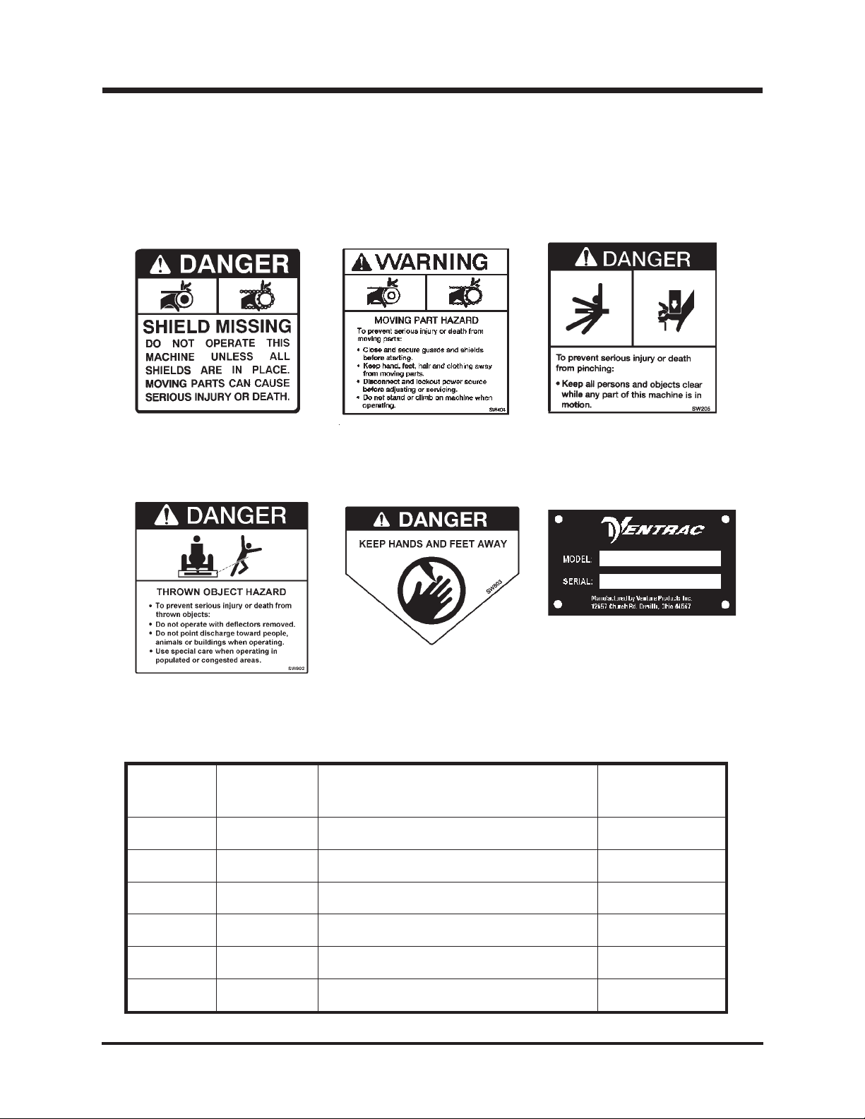
Decals
The following decals must be maintained on your Ventrac mower. If any decals are
faded or missing, contact your dealer promptly for replacements.
A B C
F
E
D
Decal
A E-2,#37 Danger Shield Missing 00.0062
B E-8,#15 Warning Moving Part Hazard 00.0101
C E-8, #3 Danger Pinching Hazard 00.0102
D E-2, #14 Thrown Object Hazard 00.0122
E E-2, #13 Keep Hands and Feet Away 00.0123
F E-2, #39 Ventrac Serial No. Plate N/A
Page &
Location
Description Part Number
B-2

SAFETY
General Safety Procedures
for Ventrac Tractors, Attachments, & Accessories
Read and understand the operator’s manual before operating this equipment.
Observe and follow all safety decals.
DO NOT let children or any untrained person operate the tractor or attachment.
Make sure that all operators of this equipment are thoroughly trained in using it
safely.
Never allow additional riders on the tractor or attachments.
DO NOT operate tractor or attachments if you are under the influence of alcohol,
drugs, medication that may impair judgment or cause drowsiness, or if you are not
feeling well.
Operate all controls from the operators seat only.
Before operating equipment, make sure all shields are in place and fastened.
Ensure the attachment or accessory is locked or fastened securely to the tractor
(power unit) before operating. See tractor manual for locking procedure.
Ensure that all bystanders are clear of the tractor and attachment before operating.
Be especially careful and observant if other people are present. Never assume that
bystanders will remain where you last saw them.
Always look in the direction the tractor is moving.
Never direct the discharge of any attachment in the direction of people, animals,
buildings, vehicles, or objects of value.
Immediately stop at any sign of equipment failure and correct the problem before
continuing to operate. An unusual noise can be a warning of equipment failure.
Before adjusting, cleaning, lubricating, or changing parts on the tractor or attachment,
engage the parking brake, lower the attachment to the ground, stop the engine, and
remove the ignition key.
To prevent the risk of uncontrolled equipment movement on tractors equipped with 2
speed axles, always shift the transaxle range with the power unit stationary on level
ground and with the parking brake engaged.
If equipment is to be left unattended, engage the parking brake, lower the attachment
to the ground, stop the engine, and remove the ignition key.
B-3
SAFETY
HM600, HM720, and HP720 Safety Procedures
Before making any repairs or adjustments, lower
attachment to the ground, set parking brake, shut
the engine off, and remove the key.
Read and understand the operator’s manual before
operating this equipment.
Before mowing, clear the area of stones, sticks, and other foreign objects that can be
thrown by the mower.
Use extra care when mowing around trees, shrubs, and other objects that may block
your vision.
Never mow with the discharge chute flipped up or missing! The hinge feature is
provided only for transport and storage.
Disengage the PTO when you are not mowing.
When mowing on a steep incline, always mow uphill and downhill. Never mow across a
steep incline.
B-4

OPERATION
Operating Instructions
Attaching:
1. Drive the tractor slowly forward into the hitch arms of the mower. Align the lift arms
with the mower hitch arms by raising or lowering the front hitch and complete
the engagement. Note:
when mower cutting height is set in a low position. Set cutting height to the highest
position.
2. Once completely engaged, close the front hitch locking lever.*
3. Engage the parking brake and shut off engine.
4. Place attachment belt over the outside groove of the PTO drive pulley on the tractor.
Ensure the belt is properly seated in each pulley.
5. Engage the PTO spring tension lever.*
6. Engage the weight transfer system as desired.*
Note: It is recommended for most mowing operations that the weight transfer system be
fully engaged when using the mower deck. Adjust as required.
Mower arms may be too low to engage tractor hitch arms
Detaching:
1. Park the tractor on a level surface and set the parking brake.
2. Lower the mower to the ground.
3. Shut off tractor engine.
4. Disengage the PTO spring tension lever.*
5. Remove the attachment belt from the PTO drive pulley on the tractor.
6. Disengage the hitch locking lever.*
7. Restart the tractor and slowly back away from the mower.
*Refer to tractor manual for operation of controls.
Operating Techniques and Tips:
Be sure to select or confirm that the mower is set to cut the height that you prefer.
Setting is done by lifting the handle into the catch slot, pulling the handle outward and
moving the mechanism to another position on the adjustment scale. Cutting height
range is approximately 1-3/4 to 4-3/4 inches. After selection has been engaged, release
the handle from the catch slot and return it to a horizontal position. Never
height with PTO engaged.
adjust cutting
Operator must be sitting on the tractor seat before the PTO can be engaged. The tractor
engine should be running between 2,000 and 3,000 RPM before engaging the PTO
switch. Near full engine RPM (3,600) is recommended for most mowing. If a good cut
can be maintained and there is sufficient power, reducing the engine speed by 200 or
300 RPM will result in improved fuel economy and reduction in the wear-and-tear on the
equipment.
C-1

OPERATION
Operating Techniques and Tips (cont.)
Travel to and from the area to be mowed should generally be done with the
mower raised in transport position by the tractor hydraulics. This saves the
wear-and-tear on the mower and needless scuffing and rolling over the various
surfaces between mowing jobs. Moderate speed should be used in transport in
order to maintain control and reduce the shock load from uneven terrain.
Disengage the PTO to prevent air turbulence over dusty surfaces and/or when
traveling over rough terrain.
When mowing, always place the front hitch S.D.L.A. lever in the FLOAT position
by moving it outward to the second position until the detent engages. The lever
will stay in this position after engagement.
Wet or lush grass has some tendency to build up under the deck. Periodic
checking, especially if mowing performance seems to be reduced, will let the
operator know if the deck should be cleaned.
Many operators prefer to mow back and forth in order to create the popular stripe
pattern in the cut grass. The full length roller very effectively rolls the cut grass
in the direction of travel.
Blades should be kept in good condition. Sharp blades will increase
efficiency and improve the quality of cut.
When mowing grass on level to gently rolling terrain, the tractor can be
operated in HIGH range in most conditions. If the grass is tall or mowing
conditions are difficult, use LOW range. When mowing slopes, always
use LOW range with the engine at full throttle.
Be very cautious when mowing slopes. It is
recommended that weight transfer be engaged and
that the front hitch is set in FLOAT position.
C-2

OPERATION
Mulching Kit
The mulching kit consists of 3 baffles, a discharge cover and 10 carriage bolts and nuts.
Kits are HM600—39.55150
turn the deck upside down or if mounted on the tractor (with park bake engaged and
ignition key removed), tilt the deck to the servicing position and install the kit according
to the drawing below.
NOTE: 1-The longest baffle goes in the center.
2-The deepest baffle goes to the left (discharge) side.
3-The saw-toothed edges will be facing the ground in mowing
position when installed.
4-Check for blade clearance. The saw-tooth edges should extend
beyond the end of the blade at least 1/4 inch. Slight reshaping of
baffles may be necessary for proper fit.
If the deck has been used, make sure it is clean before installation of parts. Blades do
not have to be removed for the installation but it is important that the blades are sharp
and in good condition. Low lift or mulch blades are recommended for mulching. Install
all parts before tightening the bolts. Once all parts are in place, tighten all ten bolts
(Torque to 14-16 ft/lbs.) A 1/2” box end wrench or socket drive is recommended in
order to tighten the bolts securely.
and HM720—39.55151 . To install the mulching kit, simply
Mulching procedures may vary greatly due to climate, type of grass and soil conditions.
Some trial and error may prove helpful in getting the best results. In general it is best to
mow frequently and in dry conditions. Leaves are usually cut up and dispersed better
when some grass is cut in the mulching process. Generally a little more power is
required for mulching. When grass is tender, heavy, and/or wet, frequent deck cleaning
may be necessary. After mowing for a few minutes, turn the engine off, raise the deck,
and make a quick check on all ten bolts to assure that they are tight!
C-3

MAINTENANCE
Lubrication
Grease zerks are located as shown below. Apply 2-3 pumps of grease per spindle
approximately every 50
overgrease. In very dirty, sandy, or wet conditions, more frequent greasing may be
advisable.
hours of operation. All others bearings—one pump max! Do not
Removal and Reinstallation of Mower Blades for Sharpening or
Replacement:
Caution: Blades may be sharp, wear heavy gloves when working with blades.
1. Park tractor on a smooth, level surface.
2. Raise deck to the highest position.
3. Set parking brake, shut the engine off, and remove the key.
4. Remove the 2 latch pins, lift the front of the mower deck to a near vertical position
and reinstall the latch pins into the same holes.
D-1

MAINTENANCE
5. To remove each blade, place a short piece of2x4wood between the end of the
blade and an appropriate structural part of the underside of the deck to prevent
rotation.
6. Loosen the blade bolt counterclockwise and remove the blade for sharpening or
replacement.
7. When reinstalling a blade, the wood block must be placed on the opposite side to
prevent rotation for tightening. Tighten so that blade is firmly held in place. (75-80
ft/lbs) Additional tightening may occur while mowing. This is due to blade rotation.
8. Always install the spindle guard between the bolt head and the bottom of the blade.
This serves as a support washer as well as reducing the potential for bearing
damage from wrapping string or wire.
Deck Belt Replacement:
(HM600 Serial# AA1001-1357) (HM720 Serial# AA1001-1188) (HP720 Serial# AA1001-1066)
If the deck belt is excessively worn or cracked, install a new belt.
This is done most easily with the deck removed from the tractor.
1. Remove the rear lid of the deck.
This is done by raising the lid and sliding it to the right to release hinge pin on the left side.
2. Remove cotter pin from cross-over support in the center of the hitch.
3. Release the belt tension by loosening the idler adjustment rod. (Refer to illustration
below.)
D-2

MAINTENANCE
Deck Belt Replacement (cont.):
4. Remove old belt. Note that one belt loop must surround the left hitch arm. This is the
reason for removing the cotter pin in the crossover support.
5. Install the new B158 belt (Part # 81.B158
72” deck) as shown in the diagram below. Begin by placing one belt loop around the
left hitch arm. Place belt into the idler pulley and then the drive pulley. Take the
belt to the right spindle pulley rotating it 1/4 turn counterclockwise.
6. Once around the pulley, follow the diagram to the other pulleys. Note: the “V” shape
of the belt should fit nicely into each pulley.
7. Tension the belt by tightening the idler adjustment rod. Spring coils should be
separated enough to slip a paper clip (approximately 1/32”) between them. Reinstall
cotter pin in crossover support.
for 60”) or B180 belt, (Part #81.B180 for
Deck Belt Replacement:
(HM600 Serial# AA1358-) (HM720 Serial# AA1189-) (HP720 Serial# AA1067-)
1. Remove the rear lid of the deck.
This is done by raising the lid and sliding it to the right to release hinge pin on the left side.
2. Release the belt tension by loosening the idler adjustment rod. (Refer to illustration
below.)
D-3

MAINTENANCE
Deck Belt Replacement (cont.):
3. Remove the left hitch arm mounting bolt and lift the hitch arm up from the mounting
brackets on the deck.
4. Remove old belt. Note that one belt loop must surround the left hitch arm. This is the
reason for removing the left hitch arm mounting bolt.
5. Install the new B158 belt (Part # 81.B158
72” deck) as shown in the diagram below. Begin by placing one belt loop around the
left hitch arm. Place belt into the idler pulley and then the drive pulley. Take the belt
to the right spindle pulley rotating it 1/4 turn counterclockwise.
6. Once around the pulley, follow the diagram to the other pulleys. Note: the “V” shape
of the belt should fit nicely into each pulley.
7. Reinstall the left hitch arm.
8. Tension the belt by tightening the idler adjustment rod. Spring coils should be
separated enough to slip a paper clip (approximately 1/32”) between them.
for 60”) or B180 belt, (Part #81.B180 for
PTO Drive Belt Replacement:
Remove mower from tractor. Remove pulley cover and place new belt B45
(Part #81.B045
) over pulley and left hitch arm. Reinstall cover.
Mower Tire Pressure:
Mower tire inflation pressure should be maintained at 8-10 psi. Pressure variables are
one cause for an uneven cut.
Deck Leveling Procedure:
(Check for bent blades before making adjustments)
1. Before making any deck leveling adjustments, check pressure in both mower tires.
Inflate or deflate to 8-10 psi.
2. Set mower on a level hard surface. Select a high cutting height position with enough
distance from floor surface to bottom side of blade for measuring.
D-4

MAINTENANCE
Deck Leveling Procedure (cont.):
3. Go to one side of the deck. Turn blade so that the tip is at the back of the deck.
Measure the distance from the floor to the blade.
4. Move to the other side. Turn that blade tip to the back of the deck. If this
measurement is different from the first, adjust the threaded rod linkage directly
above on the top side of the deck until the measurement is the same as the first
side.
5. Once the deck has been leveled side to side, rotate the same tip of the blade to the
front and measure. The distance to the floor should be the same or slightly less
than (not to exceed 1/8”) the rear measurement. Front adjustment is made by
loosening the cross bolts in the frame that extends toward each front tire. The bolts
are in slotted holes. Moving them forward lowers the deck. Moving them toward
the rear raises the deck.
Note:
difference in the front deck height.
Slight movement of the bolt in the front carrier slots will make a significant
Seasonal Storage:
Before the mower is stored, thoroughly clean both the underside of the deck and any
accumulated clippings or debris on the top side.
Sharpening Blades:
It is recommended that blades be sharpened and balanced by a professional. Maintain
balance, same bevel, and length of sharpened surface.
D-5

PARTS
MANUAL
HM600/HM720/HP720

PARTS
FIGURE 1
ILLUSTRATED DRAWING
DECK PARTS
(HM600 SER# AA1001-AA1262) (HM720 SER# AA1001-AA1134) (HP720 SER# AA1001-AA1025)
E-1

PARTS
FIGURE 1
DECK PARTS
HM600 HM720/HP720
REF. PART NO. PART NO. DESCRIPTION QTY.
1.....83.0031 .......83.0031 ........Idler Pulley ..................... 2
2.....90.0614 .......90.0614 ........3/8-16 x 1-3/4 Bolt ................. 2
3.....94.06 ........94.06..........3/8USSFlat Washer ...............3
4.....99.A12NF ......99.A12NF .......3/4SAELocknut ..................3
5.....95.12 ........95.12..........3/4SAEFlat Washer ...............3
6.....90.0608 .......90.0608 ........3/8-16 x 1 Bolt ................... 1
7.....83.0034 .......83.0036 ........Spindle Pulley ................... 3
8.....90.0636 .......90.0636 ........3/8-16 x 4-1/2 Bolt ................. 1
9.....50.0047 .......50.0047 ........Front Roller .................... 1
10....50.0046 .......50.0046 ........Front Roller Spindle ................1
11....99.A06 ........99.A06 .........3/8-16 Locknut ................... 2
12....03.0002 .......03.0002 ........Latch Pin......................2
13....00.0123 .......00.0123 ........Keep Hands & Feet Away Decal..........3
14....00.0122 .......00.0122 ........Thrown Object Hazard Decal ...........1
15....99.SF06 .......99.SF06 ........3/8USSFlange Nut ................21
16....60.0605 .......60.0664 ........Side Discharge Chute ............... 1
17....64.0602 .......64.0602 ........3/8x5/8x5/16 Bushing ..............3
18....99.SF0608......99.SF0608 .......3/8-16 x 1 Flange Bolt ...............6
19....90.0610 .......90.0610 ........3/8-16 x 1-1/4 Bolt.................12
20....95.06 ........95.06..........3/8SAEWasher .................12
21....87.0176 .......87.0176 ........Spindle Assembly .................3
22....55.0035 .......55.0035 ........Ball Bearing .................... 6
23....29.GF0001 .....29.GF0001.......1/4-28 Grease Fitting ...............3
24....87.0178 .......87.0178 ........Housing ...................... 3
25....87.0179 .......87.0179 ........Spacer ....................... 3
26....87.0181 .......87.0181 ........Spindle Shaft.................... 3
27....79.0036 .......79.0038 ........LowLiftBlade ................... 3
.....79.0035 .......79.0037 ........High Lift Blade ...................3
.....79.0046 ....................Gator Blade .................... 3
28....64.0688 .......64.0688 ........Spindle Guard ................... 3
29....91.0810 .......91.0810 ........½-20 x 1-1/4 Bolt..................3
30....99.SF05 .......99.SF05 ........5/16-18 Flange Nut ................ 2
31....42.0385 .......42.0385 ........Idler Adjustment Rod ............... 1
32....41.0048 .......41.0048 ........6”Spring ......................1
33....40.0238 .......40.0238 ........Idler Arm ...................... 1
34....99.SF0606......99.SF0606 .......3/8-16 X 3/4 Flange Bolt ..............1
35....64.0669 .......64.0669 ........Deck Carrier Slide ................. 2
36....00.0062 .......00.0062 ........Shield Missing Decal................1
37....81.B158 .......81.B180 ........Belt......................... 1
38....notavailable .....notavailable ......Serial Number Plate ................ 1
39....62.0757 .......62.0763 ........Deck ........................ 1
39................ 62.0859 ........Offset Deck, HP720 ................ 1
E-2

PARTS
FIGURE 2
ILLUSTRATED DRAWING
DECK PARTS
(HM600 SER# AA1263-AA1945) (HM720 SER# AA1135-AA1612) (HP720 SER# AA1026-AA1180)
E-3

PARTS
FIGURE 2 - DECK PARTS
HM600 HM720/HP720
REF. PART NO. PART NO. DESCRIPTION QTY.
1.....83.0031 .......83.0031 ........Idler Pulley ..................... 2
2.....90.0614 .......90.0614 ........3/8-16 x 1-3/4 Bolt ................. 2
3.....94.06 ........94.06..........3/8USSFlat Washer ............... 1
4.....99.A12NF ......99.A12NF .......3/4SAELocknut .................. 3
5.....95.12 ........95.12..........3/4SAEFlatwasher ................ 3
6.....70.8040 .......70.8041 ........Spindle Pulley Kit .................3
7.....90.0636 .......90.0636 ........3/8-16 x 4-1/2 Bolt ................. 1
8.....50.0047 .......50.0047 ........Front Roller .................... 1
9.....50.0046 .......50.0046 ........Front Roller Spindle ................ 1
10....99.A06 ........99.A06 .........3/8-16 Locknut ................... 2
11....03.0002 .......03.0002 ........Latch Pin 3/8 x 2” .................2
12....00.0123 .......00.0123 ........Keep Hands & Feet Away Decal..........3
13....90.0606 .......90.0606 ........3/8-16 x 3/4 Bolt .................. 1
14....41.0020 .......41.0020 ........Spring ....................... 1
15....90.0608 .......90.0608 ........3/8-16 x 1 Bolt ................... 2
16....95.06 ........95.06..........3/8SAEWasher (As required) ..........20
17....62.0889 .......62.0891 ........Side Discharge Chute ............... 1
18....00.0122 .......00.0122 ........Decal - Thrown Object Hazard...........1
19....64.0602 .......64.0602 ........3/8x5/8x5/16 Bushing ..............3
20....99.SF06 .......99.SF06 ........3/8-16 Flange Nut ................. 19
21....90.0610 .......90.0610 ........3/8-16 x 1-1/4 Bolt.................12
22....55.0035 .......55.0035 ........Ball Bearing .................... 6
23....87.0178 .......87.0178 ........Housing ...................... 3
24....87.0179 .......87.0179 ........Spacer ....................... 3
25....29.GF0001 .....29.GF0001.......1/4-28 Grease Fitting ...............3
26....70.8039 .......70.8039 ........Spindle Shaft Kit ..................3
27....70.8037 .......70.8037 ........Spindle Assembly Kit ...............3
28....79.0036 .......79.0038 ........LowLiftBlade ................... 3
.....79.0035 .......79.0037 ........High Lift Blade ...................3
.....79.0046 ....................Gator Blade .................... 3
29....64.0688 .......64.0688 ........Spindle Guard ................... 3
30....91.0810 .......91.0810 ........1/2-20 x 1-1/4 Bolt .................3
31....99.SF05 .......99.SF05 ........5/16-18 Flange Nut ................ 2
32....42.0385 .......42.0385 ........Idler Adjustment Rod ............... 1
33....41.0048 .......41.0048 ........Spring ....................... 1
34....40.0238 .......40.0238 ........Idler Arm ...................... 1
35....99.SF0606......99.SF0606 .......3/8-16 x 3/4 Flange Bolt ..............4
36....64.0669 .......64.0669 ........Deck Carrier Slide ................. 2
37....81.B158 .......81.B180 ........Belt......................... 1
38....00.0062 .......00.0062 ........Decal - Shield Missing ...............1
39....notavailable .....notavailable ......Serial Number Plate ................ 1
40....62.0888 .......62.0890 ........Deck ........................ 1
40................ 62.0900 ........Offset Deck, HP720 ................ 1
41....00.0102 .......00.0102 ........Pinch Hazard Decal ................1
E-4

PARTS
FIGURE 3
ILLUSTRATED DRAWING
DECK PARTS
(HM600 SER# AB1946--) (HM720 SER# AB1613--) (HP720 SER# AB1181--)
E-5

PARTS
FIGURE 3
DECK PARTS
HM600 HM720/HP720
REF. PART NO. PART NO. DESCRIPTION QTY.
1.....83.0031 .......83.0031 ........Idler Pulley ..................... 2
2.....90.0614 .......90.0614 ........3/8-16 x 1-3/4 Bolt ................. 2
3.....94.06 ........94.06..........3/8USSFlat Washer ............... 1
4.....90.0636 .......90.0636 ........3/8-16 x 4-1/2 Bolt ................. 1
5.....50.0047 .......50.0047 ........Front Roller .................... 1
6.....50.0046 .......50.0046 ........Front Roller Spindle ................ 1
7.....99.A06........99.A06 .........3/8-16 Lock Nut .................. 3
8.....03.0002 .......03.0002 ........Latch Pin, 3/8 x 2” .................2
9.....00.0123 .......00.0123 ........Decal, Keep Hands & Feet Away .........3
10....90.0606 .......90.0606 ........3/8-16 x 3/4 Bolt .................. 1
11....41.0020 .......41.0020 ........Spring ....................... 1
12....90.0608 .......90.0608 ........3/8-16 x 1 Bolt ................... 2
13....95.06 ........95.06..........3/8SAEFlat Washer (as required) ........8
14....62.0889 .......62.0891 ........Side Discharge Chute ............... 1
15....00.0122 .......00.0122 ........Decal, Thrown Object Hazard ...........1
16....64.0602 .......64.0602 ........3/8x5/8x5/16 Bushing ..............3
17....99.SF06 .......99.SF06 ........3/8-16 Flange Nut .................9
18....99.SF05 .......99.SF05 ........5/16-18 Flange Nut ................ 2
19....42.0385 .......42.0385 ........Idler Adjustment Rod ............... 1
20....41.0048 .......41.0048 ........Spring ....................... 1
21....40.0238 .......40.0238 ........Idler Arm ...................... 1
22....99.SF0606......99.SF0606 .......3/8-16 x 3/4 Flange Bolt ..............4
23....64.0669 .......64.0669 ........Deck Carrier Slide ................. 2
24....00.0062 .......00.0062 ........Decal, Shield Missing ............... 1
25....00.0102 .......00.0102 ........Decal, Danger - Pinching Hazard .........1
26....notavailable .....notavailable ......Decal, Serial Number Plate ............ 1
27....62.0888 .......62.0890 ........Deck, HM ..................... 1
.................62.0900 ........Offset Deck, HP720 ................ 1
E-6

PARTS
FIGURE 4
ILLUSTRATED DRAWING
SPINDLE ASSEMBLY
(HM600 SER# AB1946--) (HM720 SER# AB1613--) (HP720 SER# AB1181--)
E-7

PARTS
FIGURE 4
SPINDLE ASSEMBLY
HM600 HM720/HP720
REF. PART NO. PART NO. DESCRIPTION QTY.
1.....81.B158 .......81.B180 ........Belt......................... 1
2.....99.A12NF ......99.A12NF .......3/4-16 Lock Nut .................. 3
3.....99.B0057-2 .....99.B0057-2 ......10ga.x3/4x1-1/4 Machine Washer .......3
4.....83.0051 .......83.0052 ........Spindle Pulley ................... 3
5.....85.B0080 ......85.B0080........Pulley Spacer ................... 3
6.....55.0057 .......55.0057 ........Ball Bearing, 2-sided Shield ............3
7.....90.0610 .......90.0610 ........3/8-16 x 1-1/4 Bolt................. 12
8.....95.06 ........95.06..........3/8SAEFlat Washer ...............12
9.....99.SF06 .......99.SF06 ........3/8-16 Flange Nut .................12
10....29.GF0017 .....29.GF0017.......Relief Fitting .................... 3
11....55.0035 .......55.0035 ........Ball Bearing, Single Shield.............3
12....87.0209-1 ......87.0209-1 .......Spindle Housing .................. 3
13....29.GF0001 .....29.GF0001.......1/4-28 Grease Fitting ...............3
14....87.0209 .......87.0209 ........Spindle Assembly, Right Hand Thread.......3
15....87.0209-2 ......87.0209-2 .......Spindle Shaft, Right Hand Thread .........3
16....85.W0406 ......85.W0406 .......1/4x3/4Woodruff Key...............3
17....87.0210 .......87.0210 ........Spindle Flange Shield ...............3
18....79.0036 .......79.0038 ........LowLiftBlade ................... 3
.....79.0035 .......79.0037 ........High Lift Blade ...................3
.....79.0046 ....................Gator Blade .................... 3
19....64.0688 .......64.0688 ........Spindle Guard ................... 3
20....91.0814 .......91.0814 ........1/2-20 x 1-3/4 Bolt .................3
21....99.B0091 ......99.B0091........Blade Washer ................... 3
22....85.B0082 ......85.B0082........Bushing, Spindle Shaft Spacer........... 3
E-8

PARTS
FIGURE 5
ILLUSTRATED DRAWING
CARRIER FRAME PARTS
(HM600 SER# AA1001-AA1262) (HM720 SER# AA1001-AA1134) (HP720 SER# AA1001-AA1025)
E-9

PARTS
FIGURE 5
CARRIER FRAME PARTS
HM600 HM720/HP720
REF. PART NO. PART NO. DESCRIPTION QTY.
1.....60.0662 .......60.0676 ........Deck Shield ....................1
1.................60.0758 ........Offset Deck Shield, HP720 ............1
2.....00.0189 .......00.0189 ........Ventrac Decal ................... 1
3.....00.0192 .......00.0192 ........V-Decal ...................... 1
4.....62.0758 .......62.0764 ........Carrier Frame ...................1
5.....99.SF06 .......99.SF06 ........3/8-16 Flange Nut .................7
6.....94.06 ........94.06..........3/8USSWasher ..................4
7.....90.0640 .......90.0640 ........3/8-16 x 5 Bolt ................... 2
8.....64.0671 .......64.0671 ........Deck/Carrier Spacer ................2
9.....64.0682 .......64.0682 ........Deck Shield Spring.................1
10....95.05 ........95.05..........5/16 SAE Flat Washer ...............3
11....41.0021 .......41.0021 ........1/2ODx2-3/4 Compression Spring ........ 1
12....99.A05 ........99.A05 .........5/16-18 Locknut .................. 1
13....90.0524 .......90.0524 ........5/16-18 x 3 Bolt .................. 1
14....43.006 ........43.006 .........3/8-24 Spherical Rod End .............4
15....90.0610 .......90.0610 ........3/8-16 x 1-1/4 Bolt .................2
16....95.06 ........95.06..........3/8SAEWasher .................14
17....93.06 ........93.06..........3/8-24 Nut ..................... 4
18....99.J0640NFZ ....99.J0640NFZ .....Height Adjuster Rod ................ 2
19....90.0612 .......90.0612 ........3/8-16 x 1-1/2 Bolt .................8
20....42.0386 .......42.0388 ........Height Adjuster Cross Shaft ............1
21....99.SF0506......99.SF0506 .......5/16-18 x 3/4 Flange Bolt .............3
22....41.0039 .......41.0039 ........9/16 OD x 5/8 Compression Spring ........2
23....64.0678 .......64.0678 ........Height Adjuster Bracket ..............1
24....90.0414 .......90.0414 ........1/4-20 x 1-3/4 Bolt .................1
25....95.04 ........95.04..........1/4SAEWasher .................. 2
26....99.A04 ........99.A04 .........1/4-20 Lock Nut .................. 1
27....42.0387 .......42.0387 ........Height Adjuster Handle ..............1
28....47.0111 .......47.0111 ........ Handle Grip ....................1
29....64.0668 .......64.0668 ........Height Adjuster Plate ............... 1
30....64.0679 .......64.0679 ........Height Adjuster Plate Spacer ...........2
31....99.SF05 .......99.SF05 ........5/16-18 Flange Nut ................ 3
32....99.A06 ........99.A06 .........3/8-16 Lock Nut .................. 6
33....99.SF0608......99.SF0608 .......3/8-16 x 1 Flange Bolt ...............1
34....00.0166 .......00.0166 ........Belt Diagram Decal ................1
E-10

PARTS
FIGURE 6
ILLUSTRATED DRAWING
DECK PARTS
(HM600 SER# AA1263--) (HM720 SER# AA1135--) (HP720 SER# AA1026)
E-11

PARTS
FIGURE 6
DECK PARTS
HM600 HM720/HP720
REF. PART NO. PART NO. DESCRIPTION QTY.
1.....60.0662 .......60.0676 ........Deck Shield ....................1
1.................60.0758 ........Offset Deck Shield, HP720 ............1
2.....00.0192 .......00.0192 ........V-Decal ...................... 1
3.....62.0758 .......62.0764 ........Carrier Frame ...................1
4.....00.0139 .......00.0139 ........Ventrac Decal ................... 1
5.....99.A06........99.A06 .........3/8-16 Lock Nut .................. 3
6.....94.06 ........94.06..........3/8USSFlat Washer ............... 6
7.....90.0640 .......90.0640 ........3/8-16 x 5 Bolt ................... 2
8.....64.1000 .......64.1000 ........Deck/Carrier Slide Pin ............... 2
9.....64.0682 .......64.0682 ........Deck Shield Spring.................1
10....95.05 ........95.05..........5/16 SAE Flat Washer ...............5
11....99.A05 ........99.A05 .........5/16-18 Lock Nut.................. 2
12....41.0021 .......41.0021 ........1/2ODx2-3/4 Compression Spring ........1
13....90.0524 .......90.0524 ........5/16-18 x 3 Bolt .................. 1
14....90.0612 .......90.0612 ........3/8-16 x 1-1/2 Bolt .................2
15....95.06 ........95.06..........3/8SAEWasher .................. 7
16....43.006 ........43.006 .........3/8-24 Spherical Rod End .............4
17....93.06 ........93.06..........3/8-24 Nut ..................... 4
18....99.J0640NFZ ....99.J0640NFZ .....Height Adjuster Rod ................ 2
19....99.SF06 .......99.SF06 ........3/8-16 Flange Nut .................9
20....42.0431 .......42.0432 ........Height Adjuster Cross Shaft ............1
21....90.0614 .......90.0614 ........3/8-16 x 1-3/4 Bolt .................1
22....90.0508 .......90.0508 ........5/16-18 x 1 Bolt .................. 1
23....64.0903 .......64.0903 ........Height Adjuster Bracket ..............1
24....41.0039 .......41.0039 ........9/16 OD x 5/8 Compression Spring ........1
25....40.0289 .......40.0289 ........Height Adjuster Selector Handle..........1
26....47.0086 .......47.0086 ........Handle Grip .................... 1
27....64.0904 .......64.0904 ........Height Adjuster Plate ............... 1
28....64.0905 .......64.0905 ........Height Adjuster Plate Spacer ...........2
29....90.0618 .......90.0618 ........3/8-16 x 2-1/4 Bolt .................2
30....99.SF0608......99.SF0608 .......3/8-16 x 1 Flange Bolt ...............1
31....00.0166 .......00.0166 ........Belt Diagram Decal ................1
32....90.0610 .......90.0610 ........3/8-16 x 1-1/4 Bolt .................2
33....00.0100 .......00.0100 ........Made in the USA Decal .............. 1
E-12

PARTS
FIGURE 7
ILLUSTRATED DRAWING
CASTER & REAR ROLLER PARTS
E-13

PARTS
FIGURE 7
CASTER & REAR ROLLER PARTS
HM600 HM720/HP720
REF. PART NO. PART NO. DESCRIPTION QTY.
1.....53.0080 .......53.0080 ........Dust Cap ...................... 2
2.....99.A12NF ......99.A12NF .......3/4-16 Locknut ................... 2
3.....55.0023 .......55.0023 .........75x1.78 Ball Bearing............... 4
4.....04.0013 .......04.0013 .........068 x 1.75 Internal Snap Ring...........2
5.....99.B0052 ......99.B0052........16ga.x3/4 x 1 Shim ............... 2
6.....99.B0057-2 .....99.B0057-2 ......10Ga.x3/4x1-1/4 Machinery Washer ......4
7.....99.A06........99.A06 .........3/8-16 Locknut ................... 2
8.....53.0086 .......53.0086 ........Caster Wheel Assembly ..............2
9.....50.0050 .......50.0050 ........Axle Tube .....................2
10....90.0656 .......90.0656 ........3/8-16 x 7 Bolt (Welded 1/4” Caster only) .....
10....90.0660 .......90.0660 ........3/8-16 x 7-1/2 Bolt (Formed 3/8” Caster) .....2
11....50.0049 .......50.0049 ........Caster Spindle ...................2
12....04.0016 .......04.0016 ........1"External Snap Ring ...............2
13....95.16 ........95.16..........1”SAEWasher .................. 4
14....50.0044 .......50.0044 ........EndRoller ..................... 2
15....64.0681 .......64.0681 ........Rear Roller Spacer................. 2
16....99.SF0508......99.SF0508 .......5/16-18 x 1 Flange Bolt ..............4
17....99.SF05 .......99.SF05 ........5/16-18 Flange Nut ................ 4
18....55.FB16016 .....55.FB16016 ......1"Flange Block Bearing ..............1
19....80.0292 .......80.0293 ........Rear Roller..................... 1
20....95.06 ........95.06..........3/8SAEFlat Washer ...............4
21....55.FB16016-7 ....55.FB16016-7 .....1”Flange Block Bearing ..............1
22....95.12 ........95.12..........3/4SAEFlat Washer (As needed) .........2
23....47.0215 .......47.0215 ........EndCap(QTYper1ofRef8)...........2
24....44.0201 .......44.0201 ........Felt Seal (QTY per 1 of Ref 8) ...........2
25....55.0053 .......55.0053 ........Roller Bearings (QTY per 1 of Ref 8) .......2
26....99.G0013 ......99.G0013 .......Inner Spacer (QTY per 1 of Ref 8) .........4
E-14

PARTS
FIGURE 8
ILLUSTRATED DRAWING
HITCH ASSEMBLY PARTS
(HM600 SER# AA1001-AA1357) (HM720 SER# AA1001-AA1188) (HP720 SER# AA1001-AA1066)
E-15

PARTS
FIGURE 8
HITCH ASSEMBLY PARTS
HM600 HM720/HP720
REF. PART NO. PART NO. DESCRIPTION QTY.
1.....99.E0004 ......99.E0004........1/4-20 Wing Nut .................. 1
2.....60.0665 .......60.0665 ........Outer Drive Pulley Shield .............1
3.....00.0102 .......00.0102 ........Pinching Hazard Decal ..............1
4.....62.0759 .......62.0773 ........LeftHitch Arm ................... 1
5.....97.0504 .......97.0504 ........5/16-18 x 1/2 Carriage Bolt ............2
6.....60.0663 .......60.0663 ........Inner Drive Pulley Shield..............1
7.....99.SF05 .......99.SF05 ........5/16-18 Flange Nut ................6
8.....83.H16S .......83.H16S ........1"Split Bushing ..................2
9.....83.BK50H ......83.BK45H .......Inner Drive Pulley .................1
10....99.SF0508......99.SF0508 .......5/16-18 x 1 Flange Bolt ..............4
11....55.FB16016-1 ....55.FB16016-1 .....1"Flange Block Bearing ..............2
12....99.A08 ........99.A08 .........1/2-13 Locknut ................... 2
13....64.0680 .......64.0680 ........LiftArmBushing .................. 2
14....90.0818 .......90.0818 ........1/2-13 x 2-1/4 Bolt .................2
15....00.0101 .......00.0101 ........Moving Part Hazard Decal ............. 1
16....62.0760 .......62.0774 ........Right Hitch Arm ..................1
17....02.CP0512 .....02.CP0512.......5/32 x 1-1/2 Cotter Pin ............... 1
18....95.08 ........95.08..........1/2SAEWasher .................. 2
19....83.BK55H ......83.BK55H .......Outer Drive Pulley ................. 1
20....80.0291 .......80.0294 ........Drive Shaft ..................... 1
21....81.B045 .......81.B045 ........B45Belt ...................... 1
22....85.K0410 ......85.K0410........1/4x1-1/4 Key...................2
23....90.0410 .......90.0410 ........1/4-20 x 1-1/4 Bolt .................1
24....99.SF04 .......99.SF04 ........1/4-20 Flange Nut .................2
E-16

PARTS
FIGURE 9
ILLUSTRATED DRAWING
HITCH ASSEMBLY PARTS
(HM600 SER# AA1358--) (HM720 SER# AA1189--) (HP720 SER# AA1067--)
E-17

PARTS
FIGURE 9
HITCH ASSEMBLY PARTS
HM600 HM720/HP720
REF. PART NO. PART NO. DESCRIPTION QTY.
1.....99.E0004 ......99.E0004........1/4-20 Wing Nut .................. 1
2.....60.0665 .......60.0665 ........Outer Drive Pulley Shield .............1
3.....00.0101 .......00.0101 ........Moving Parts Hazard Decal ............1
4.....62.0930 .......62.0932 ........LeftHitch Arm ................... 1
5.....97.0504 .......97.0504 ........5/16-18 x 1/2 Carriage Bolt ............2
6.....60.0663 .......60.0663 ........Inner Drive Pulley Shield..............1
7.....99.SF05 .......99.SF05 ........5/16-18 Flange Nut ................8
8.....83.H16S .......83.H16S ........1"Split Bushing ..................2
9.....83.BK50H ......83.BK45H .......Inner Drive Pulley .................1
10....99.SF0508......99.SF0508 .......5/16-18 x 1 Flange Bolt ..............4
11....55.FB16016-1 ....55.FB16016-1 .....1"Flange Block Bearing ..............2
12....99.A08 ........99.A08 .........1/2-13 Locknut ................... 2
13....85.B0075 ......85.B0075........Nylon Bushing ................... 2
14....90.0818 .......90.0818 ........1/2-13 x 2-1/4 Bolt .................2
15....29.GF0001 .....29.GF0001.......1/4SAEStraight Grease Fitting .......... 2
16....62.0931 .......62.0933 ........Right Hitch Arm ..................1
17....42.0450 .......42.0450 ........Spacing Link ....................1
18....95.08 ........95.08..........1/2SAEWasher .................. 6
19....83.BK55H ......83.BK55H .......Outer Drive Pulley ................. 1
20....80.0291 .......80.0294 ........Drive Shaft ..................... 1
21....81.B045 .......81.B045 ........B45Belt ...................... 1
22....85.K0410 ......85.K0410........1/4x1-1/4 Key...................2
23....90.0410 .......90.0410 ........1/4-20 x 1-1/4 Bolt .................1
24....99.SF04 .......99.SF04 ........1/4-20 Flange Nut .................2
25....99.SF0506......99.SF0506 .......5/16-18 x 3/4 Flange Bolt .............2
E-18

LIMITED WARRANTY – VENTRAC TURF EQUIPMENT
Venture Products, Inc. (shall be referred to as V.P.I.) warrants on the terms and conditions herein, that it
will repair, replace, or adjust any part manufactured by Venture Products Inc. and found by Venture
Products Inc to be defective in material and / or workmanship.
Effective September 1
limited to Three (3) years from original purchase date. Ventrac Tractors & Attachments used
Commercially or for any income producing purpose is limited to Two (2) years from original purchase
date. Ventrac ET200 turbine blower (turbine only) is limited to Two (2) years
Ventrac HG150 generator is limited to One (1) year
Attachments used for Rental
such as: 3-point hitch, foot pedal, dual wheel kit, etc. will be covered under the above warranty periods as
they would apply provided they are installed by an Authorized Ventrac Dealer.) This warranty may be
transferred and will carry the remainder of the warranty starting from the Original Purchase/Registration
date with the dealership and/or V.P.I. In the event that product/s originally registered as (3) year
Residential use are to be transferred to a commercial user the warranty would change to the remainder of
(2) year Commercial use
V.P.I.
If this warranty covers a consumer product as defined by the Magnusson-Moss warranty act, no warranties,
express or implied, (including, but not limited to, the warranty of merchantability or fitness for a particular
purpose) shall extend beyond the applicable time period stated in bold face type above.
If this warranty covers a product used commercially or for any income producing purpose, the foregoing
warranties are in lieu of all other warranties and no representations, guarantees or warranties, express or
implied, (including, but not limited to, a warranty of merchantability or fitness for a particular purpose), are
made by V.P.I. in connection with the manufacture or sale of its products.
The engine warranty is covered by its respective engine manufacturer. Please refer to the engine
manufacturer’s warranty statement that is included in the owner’s manual. V.P.I. does not handle warranty
adjustments on engines. Engine warranties should be referred to the nearest authorized service outlet of the
engine manufacturer.
The Ventrac turf equipment, including any defective parts, must be returned to an Authorized Ventrac
Dealer within the warranty period. The warranty shall extend to the cost to repair or replace (as determined
by V.P.I.) the defective part. The expense of pickup and delivery of equipment, service call drive time
or any transportation expense incurred for warranty repair is the sole responsibility of the owner
and is not covered under warranty by Ventrac and/or V.P.I. V.P.I.’s responsibility in respect to claims
is limited to making the required repairs or replacements, and no claim of breach of warranty shall be cause
for cancellation or rescission of the contract of sale of any Ventrac equipment. Proof of purchase may be
required by the dealer to substantiate any warranty claim. Only warranty work performed and submitted by
an Authorized Ventrac Dealer may be eligible for warranty credit.
This warranty extends only to Ventrac turf equipment operated under normal conditions and properly
serviced and maintained. The warranty expressly does NOT cover: (a) any defects, damage or
deterioration due to normal use, wear and tear, or exposure; (b) normal maintenance services, such as
cleaning, lubrication, oil change; (c) replacement of service items, such as oil, lubricants, spark plugs, belts,
rubber hoses or other items subject to normal service replacement; (d) damage or defects arising out of, or
relating to abuse, misuse, neglect, alteration, negligence or accident; (e) repair or replacement arising from
st
2004, Ventrac warranty on Tractors & Attachments for Residential use only is
from original purchase date.
from original purchase date. Ventrac Tractors &
is limited to 180 days from original purchase date. (NOTE: All accessories
starting from the Original Purchase/Registration date with the dealership and/or
9 - 2

LIMITED WARRANTY – VENTRAC TURF EQUIPMENT
operation of, or use of the turf equipment which is not in accordance with operating instructions
as specified in the operator’s manual or other operational instructions provided by V.P.I.; (f)
repair or
or modified so as to, in the determination of V.P.I., adversely affect the operation, performance or
durability of the equipment or that has altered, modified or affected the turf equipment so as to change the
intended use of the product; (g) repair or replacement necessitated by the use of parts, accessories or
supplies, including gasoline, oil or lubricants, incompatible with the turf equipment or other than as
recommended in the operator’s manual or other operational instructions provided by V.P.I.; (h) repairs or
replacements resulting from parts or accessories which have adversely affected the operation, performance
or durability of the turf equipment; or (i) damage or defects due to or arising out of repair of Ventrac turf
equipment by person or persons other than an authorized Ventrac service dealer or the installation of parts
other than genuine Ventrac parts or Ventrac recommended parts.
The sole liability of V.P.I. with respect to this warranty shall be repair and replacement as set forth herein.
V.P.I. shall have no liability for any other cost, loss, or damage. In particular V.P.I shall have no liability or
responsibility for: (i) expenses relating to gasoline, oil, lubricants; (ii) loss, cost or expense relating to
transportation or delivery of turf equipment from the location of owner or location where used by owner to
or from any Authorized Ventrac Dealer; (iii) travel time, overtime, after hours time or other extraordinary
repair charges or charge relating to repairs or replacements outside of normal business hours at the place of
business of an Authorized Ventrac Dealer; (iv) rental of like or similar replacement equipment during the
period of any warranty repair or replacement work; (v) any telephone or telegram charges; (vi) loss or
damage to person or property other than that covered by the terms of this warranty; (vii) any claims for lost
revenue, lost profit or additional cost or expense incurred as a result of a claim of breach of warranty; or
(viii) attorney’s fees.
The remedies of buyer set forth herein are exclusive and are in lieu of all other remedies. The liability of
V.P.I., whether in contract, tort, under any warranty, or otherwise, shall not extend beyond its obligation as
set forth herein. V.P.I. shall not be liable for cost of removal or installation nor shall V.P.I. be responsible
for any direct, indirect, special or consequential damages of any nature. In no event shall V.P.I. be liable
for any sum in excess of the price received for the goods for which liability is claimed.
There are no representations or warranties which have been authorized to the buyer of the turf equipment
other than set forth in this warranty. Any and all statements or representations made by any seller of this
equipment, including those set forth in any sales literature or made orally by any sales representative, are
superceded by the terms of this warranty. Any affirmation of fact or promise made by V.P.I. or any of its
representatives to the buyer which relates to the goods that are the subject to this warranty shall not be
regarded as part of the basis of the bargain and shall not be deemed to create any express warranty that such
goods shall conform to the affirmation or promise.
No employee, distributor, or representative is authorized to change the foregoing warranties in any way or
grant any other warranty on behalf of V.P.I.
Some states do not allow limitations on how long an implied warranty lasts or allow the exclusion on
limitation of incidental or consequential damages, so the above limitation or exclusion may not apply to
you.
This warranty gives you specific legal rights, and you may also have other rights which vary from state to
state.
This warranty applies to all Ventrac turf equipment sold in the United States and Canada.
replacement arising as a result of any operation from Ventrac turf equipment that has been altered
9 - 3

Ventrac Engine & Component Warranties
VENDOR VENTRAC
PRODUCT
Kawasaki
(Engines)
Vanguard
(Engines)
Peerless Gear & Machine
Division of Tecumseh
(Transaxles)
Sauer-Danfoss
(Hydraulic pumps & motors)
Sauer-Danfoss
(Steering & Control Valves)
Hydro-Gear
(Transaxles)
Titan Tire 3000 Series
Carlisle Tire 4200, 4100 Series
*3rd year prorated for consumer application – 50% of parts & labor
nd
*2
year prorated for commercial application – 50% of parts & labor
Contacts for locating local authorized dealer for the following:
Briggs & Stratton Corp. Kawasaki Motors Corp.
PO Box 702 Grand Rapids, MI 49512
Milwaukee, WI 53201 (800) 433-5640
800-444-7774
Tecumseh/Peerless Products Corp
Engine and Gear Service Division
Grafton, WI 53024
800-558-5402
Carlisle Tire Corp. Titan Tire Corp
23 Windham Boulevard 2345 E. Market St.
Aiken, SC 29805 Des Moines, IA 50317
800-260-7959 Warranty 800-872-2327 Warranty
3000 Series
4200, 4100 Series
4200, 4100 Series
4200, 4100 Series
4200, 4100 Series
3000 Series
4200, 4100 Series
3000 Series
4200, 4100 Series
(See engine owner’s manual)
One (1) year for commercial
Three (3) years for consumer
Two (2) year for commercial
Three (3) years for consumer
Two (2) year for commercial
One (1) year for commercial
Three (3) years; prorated after first
year for original owner only
Two (2) years for original owner Claim processed by
VENDOR
WARRANTY
Two (2) years Claim processed by a
Two (2) years
rd
3
year on major parts only
Two (2) years for consumer
application
application
rd
*3
year prorated
nd
*2
year prorated
rd
*3
year prorated
nd
*2
year prorated
Two (2) years for consumer
application
application
WARRANTY
PROCEDURE
Kawasaki authorized
servicing dealer to
Kawasaki
Claim processed by a
Vanguard authorized
servicing dealer to local
distributor
Claim processed by an
authorized Tecumseh
servicing dealer to
Tecumseh
Venture Products
processes warranty
Venture Products
processes warranty
Venture Products
processes warranty
Claims processed by
Titan Tire authorized
Carlisle Tire authorized
claim
claim
claim
dealer
dealer
 Loading...