

Ventrac 4200 Series Operator's Manual
OPERATOR’S MANUAL
VENTRAC 4200
Serial # 2929-
Revised 06/11/14
09.10051 Rev. 02
A
B
C
Vanguard
Kawasaki
C
328 East Water St.
PO Box 148
Orrville Oh 44667
www.ventrac.com
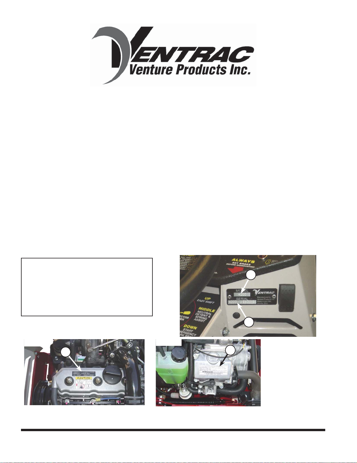
To the Owner
Contact Information and Product Identifi cation
If you need to contact an authorized Ventrac dealer for information on servicing your product,
always provide the product model and serial numbers.
Please fi ll in the following information for future reference. See the picture(s) below to fi nd the
location of the identifi cation numbers. Record them in the spaces provided.
Date of Purchase: ________________________________________________________
Dealer: _________________________________________________________________
Dealer Address: __________________________________________________________
__________________________________________________________
Dealer Phone Number: ____________________________________________________
Dealer Fax Number: ______________________________________________________
Model # (A): ______________________
Serial # (B): ______________________
Affi x Part/Serial Number label here.
Engine Serial # (C): ___________________
Vanguard
C
Kawasaki
A
B
C
Venture Products Inc. reserves the right to make changes in design or specifi cations without obligation to make
like changes on previously manufactured products.
2

enture Products Inc. is pleased to provide you with
V
your new Ventrac! We hope that Ventrac equipment
will provide you with a ONE Tractor Solution.
Listed below are just some of the items that can
provide you versatility as you use your 4200.
Please visit our web site, or contact your authorized
Ventrac dealer for a complete list of items available for
your new power unit.
Item Description
Three Point Hitch 70.4063 Light Bar 70.4030
Dual Wheels (All Terrain Tires) 70.4067 Rear Counter Weight Bar 39.56116
Dual Wheels (Turf Tires) 70.4068 Rear Bumper 70.4045
Dual Wheels (Bar Tires) 70.4069 Slope Gauge Indicator 70.0109
Canopy 70.0098 12V Rear (4 Pin Socket & Power Outlet) 70.4087
Fold Down ROPS Roll Bar 70.2004 Front 12 Volt Switch & Plug 70.4039
Suspension Seat 47.0231 Backup Alarm 70.4083
Foot Pedal 39.56108 Electric PTO Remote 70.4078
Accessories
Wheel Extensions 70.4098 Two -N-One Front Hitch 70.2001
Cab 70.2006 ES220 Spreader 39.55500
SS300 Salt Spreader 70.2011 SS575 Salt Spreader 70.2010
Item Description
Aerator with Open Spoon Tine 39.55490 Stump Grinder 39.55300
Aerator with Slitter/Slicer Tine 39.55492 Terra Rake - 52” 39.55431
Aerator with Coring Tine 39.55494 Tiller 39.55220
AeraVator (seeder kit available) 39.55460 Tough Cut Mower - 68” 39.55104
Blade - 48” 39.55251 Trencher 39.55455
Blade - 60” 39.55252 Turbine Blower 39.55340
Blade - 72” 39.55253 V-Blade 39.55271
Blower 39.55440 Versa-Loader 39.55600
Broom 39.55400
Edger 39.55330
Excavator - 30” 39.55236
Excavator - 48” 39.55230
Finish Mower - 60” 39.55105
Finish Mower - 72” 39.55106
Attachments
Finish Mower - 72” (6-1/2” offset) 39.55107
Generator - 15,000 Watt 39.55315
Power Rake 39.55435
Slip Scoop - 30” 39.55216
Slip Scoop - 48” 39.55210
Snow Blower 39.55427
Sod Cutter 39.55520
Part Num
Part Number
ber
Item Description Part Number
Accessories
Item Description Part Number
Reel Mower - 74” 39.55130
Rear Discharge Mower - 60” 39.55120
Contour Mower - 84” 39.55160
Collection Vacuum 39.55360
Attachments
3

TABLE OF CONTENTS
INTRODUCTION PAGE 7
Product Description ................................................................................................................................ 7
Why do I need an Operator’s Manual? .................................................................................................. 7
Using Your Manual .................................................................................................................................8
Manual Glossary .................................................................................................................................... 8
SAFETY PAGE 9
Safety Decals .........................................................................................................................................9
General Safety Procedures .................................................................................................................. 11
Training Required ................................................................................................................................. 11
Personal Protective Equipment Requirements ....................................................................................11
Operating Safely .................................................................................................................................. 11
Preventing Accidents ............................................................................................................................ 12
Keep Riders Off ....................................................................................................................................12
Operating On Slopes ............................................................................................................................13
Roadway Safety ...................................................................................................................................13
Truck Or Trailer Transport ....................................................................................................................13
Maintenance .........................................................................................................................................14
Fuel Safety ...........................................................................................................................................14
Hydraulic Safety ...................................................................................................................................15
Roll-Over Protective Structure ............................................................................................................. 16
Operator Interlock Systems ..................................................................................................................17
OPERATIONAL CONTROLS PAGE 18
Operational Control Locations ..............................................................................................................19
Power Take Off (PTO) Switch (A) .........................................................................................................19
Ignition Key Switch (B) .........................................................................................................................19
Throttle (C) ...........................................................................................................................................19
Glow Plug Indicator Light (D) ............................................................................................................... 19
Tachometer & Hour Meter (E) .............................................................................................................. 19
Volt Gauge (F) ......................................................................................................................................19
Engine Coolant Temperature Gauge (G) .............................................................................................19
Engine Oil Pressure Warning Light (H) ................................................................................................20
Seat Belt Light (I) ................................................................................................................................. 20
Light Switch (J) .....................................................................................................................................20
12 Volt Switches (K & L) ....................................................................................................................... 20
Engine Coolant High Temp Alarm (M) .................................................................................................. 20
Choke (N) ............................................................................................................................................. 20
Selector Lever/Parking Brake (O) ........................................................................................................ 20
Belt Tension Lever (P) ..........................................................................................................................20
Front Hitch Latch Lever (Q) ..................................................................................................................20
Front Hitch Lock (R) .............................................................................................................................20
Seat Slide Adjustment Lever (S) ..........................................................................................................20
High/Low Range Shift Handle (T) ........................................................................................................ 21
Fuel Primer Bulb Pump (W) ................................................................................................................. 21
S.D.L.A. Lever (X & Y) ......................................................................................................................... 21
Foot Pedal (Z) ...................................................................................................................................... 21
12 Volt Rear Outlet & 4-Pin Socket (AA) ..............................................................................................21
4

TABLE OF CONTENTS
OPERATIONAL CONTROLS (CONT.)
Auxiliary Hydraulic Quick Couplers (EE) .............................................................................................. 21
12 Volt 4-Pin Socket (FF) ..................................................................................................................... 22
Electric PTO Remote (5-Pin Socket) (GG) ...........................................................................................22
Seat Latch (HH) ................................................................................................................................... 22
Seat Prop (II) ........................................................................................................................................ 22
Seat Lock Lever (JJ) ............................................................................................................................ 22
GENERAL OPERATION PAGE 23
Daily Inspection .................................................................................................................................... 23
Starting the Engine ...............................................................................................................................23
Forward and Reverse ...........................................................................................................................23
Stopping the Power Unit ...................................................................................................................... 24
Detaching .............................................................................................................................................24
Operating Attachments ......................................................................................................................... 24
Front Hitch ............................................................................................................................................24
PTO Drive Belt & Pulley .......................................................................................................................24
Front Auxiliary Couplers ....................................................................................................................... 25
Weight Transfer ....................................................................................................................................25
High/Low Range ...................................................................................................................................25
Turning Radius ..................................................................................................................................... 26
3 Point Hitch (Optional Accessory) ....................................................................................................... 26
12 Volt Auxiliary Outlets (Optional Accessory) ..................................................................................... 26
Operating On Slopes ............................................................................................................................26
Towing or Pushing the Power Unit .......................................................................................................27
SERVICE PAGE 28
Cleaning & General Maintenance ........................................................................................................ 28
Service & Maintenance ........................................................................................................................ 28
Lubrication Locations ........................................................................................................................... 29
Checking Hydraulic Oil Level ............................................................................................................... 30
Checking Rear Transaxle Oil ............................................................................................................... 30
Changing Hydraulic Oil and Filter ........................................................................................................ 30
Servicing Closed Loop Hydrostatic Drive Circuit ..................................................................................30
Checking Engine RPM .........................................................................................................................31
Checking Engine Oil Level ...................................................................................................................31
Changing Engine Oil and Filter ............................................................................................................ 31
Servicing Air Filter Elements ...............................................................................................................32
Filling the Fuel Tank .............................................................................................................................33
Servicing Fuel Filter ............................................................................................................................. 34
Checking Alternator Belt
(Vanguard Engines) .............................................................................................................................35
Servicing battery .................................................................................................................................. 36
Removing and Installing Battery .......................................................................................................... 36
Cleaning Battery and Terminals ...........................................................................................................36
Using a Booster Battery ....................................................................................................................... 37
Changing the Headlight Bulb ............................................................................................................... 37
Changing the Taillights ......................................................................................................................... 38
5

TABLE OF CONTENTS
SERVICE (CONT.)
Changing the Fuses .............................................................................................................................38
Servicing Cooling System .................................................................................................................... 39
Checking Cooling System ....................................................................................................................39
Cleaning Radiator and Screen .............................................................................................................39
Draining Cooling System ......................................................................................................................40
Flushing the Cooling System ............................................................................................................... 40
Inspection of PTO Belt ......................................................................................................................... 41
PTO Belt Replacement ........................................................................................................................ 41
Parking Brake Adjustment ....................................................................................................................42
Neutral Adjustment ...............................................................................................................................42
Recommended Tire Pressure .............................................................................................................. 42
MAINTENANCE CHART PAGE 43
Maintenance Schedule - Ventrac 4200 power unit with Kawasaki engine ........................................... 43
Maintenance Checklist - Ventrac 4200 power unit with Kawasaki engine ........................................... 44
Maintenance Schedule - Ventrac 4200 power unit with Vanguard 3LC engine ...................................45
Maintenance Checklist - Ventrac 4200 power unit with Vanguard 3LC engine ....................................46
TROUBLESHOOTING PAGE 47
Engine ..................................................................................................................................................47
Electrical ...............................................................................................................................................48
Hydraulic ..............................................................................................................................................49
Power unit ............................................................................................................................................ 49
SPECIFICATIONS PAGE 50
Electrical ...............................................................................................................................................50
Power Train ..........................................................................................................................................50
Controls & instrument Panel ................................................................................................................ 50
Other features ...................................................................................................................................... 50
Dimensions ..........................................................................................................................................51
Fluid Capacities ...................................................................................................................................51
WARRANTY PAGE 52
6

INTRODUCTION
Product Description
• The 4200 is a unique all-wheel-drive power unit that distributes its weight to four equal sized fl otation
tires for excellent control, traction, stability, maneuvering, and braking.
• Performance is enhanced by a sturdy, articulated chassis which oscillates to conform to ground contour
and turns with ease via hydraulic power steering.
• The hydrostatic transmission drive is controlled with Ventrac’s patented S.D.L.A. control, which is
located next to the operator, allowing for easy control of Speed, Direction, Lift, and Auxiliary functions
with one hand.
• The high/low range selector lever enables the operator to shift both transaxles between high and low
range with a single lever.
• The 4200 is equipped with the quick and effi cient Ventrac Mount System. This allows you to attach over
30 commercial grade attachments in about a minute or less and requires no tools.
Why do I need an Operator’s Manual?
This manual has been created to help you gain the important knowledge of what is needed to safely operate, maintain, and service your power unit. It is divided into sections for convenient reference of the appropriate section.
You must read and understand the operator’s manual for each piece of Ventrac equipment you own. Reading the operator’s manual will help you become familiar with each specifi c piece of equipment. Under-
standing the operator’s manual will help you, as well as others, avoid personal injury and/or damage to
the equipment. Keep this manual with the power unit at all times. Store the manual in the manual holder
located in the storage box to the right of the operator’s seat. The manual should remain with the power unit
even if it is sold. If this manual becomes damaged or unreadable, it should be replaced immediately. Contact your local Ventrac dealer for a replacement.
When using a Ventrac attachment, be sure to read and follow the safety and operating instructions of both
the power unit and the attachment being used to ensure the safest operation possible.
The information in this manual provides the operator with the safest procedures to operate the power unit
while getting the maximum use out of the unit. Failure to follow the safety precautions listed in this manual
may result in personal injury and/or damage to the equipment.
Introduction - 7
INTRODUCTION
Using Your Manual
Throughout this manual, you will encounter special messages and symbols that identify potential safety
concerns to help you as well as others avoid personal injury or damage to the equipment.
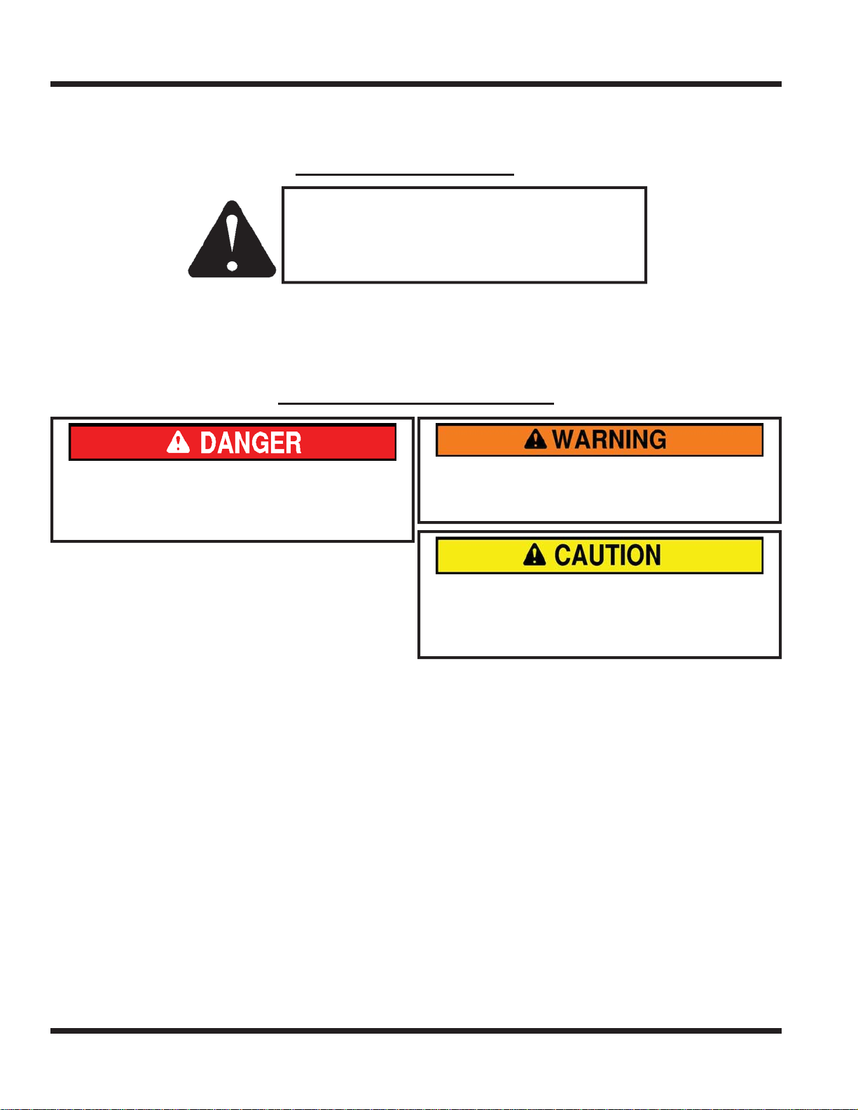
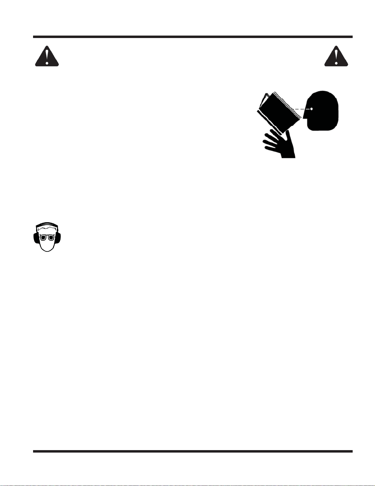
SYMBOL DEFINITIONS
ATTENTION
This symbol identifi es potential health and
safety hazards. It marks safety precautions.
Your safety and the safety of others is involved.
There are three signal words that describe the level of safety concern: Danger, Warning, and Caution.
Safety should always be the #1 priority when working on or operating equipment. Accidents are more likely
to occur when proper operating procedures are not followed or inexperienced operators are involved.
Note: Right-Hand and Left-Hand orientations may be referred to at different places throughout this manual.
Right-Hand and Left-Hand is determined as if sitting on the power unit seat facing forward.
SIGNAL WORD DEFINITIONS
Indicates an imminently hazardous situation
which, if not avoided, will result in death or
serious injury. This signal word is limited to the
most extreme cases.
Indicates a potentially hazardous situation
which, if not avoided, could result in death or
serious injury.
Indicates a potentially hazardous situation
which, if not avoided, may result in minor or
moderate injury and/or property damage. It may
also be used to alert against unsafe practices.
Manual Glossary
Power Unit A Ventrac tractor or other Ventrac engine powered device that may be operated by itself or
with an attachment or accessory.
Attachment A piece of Ventrac equipment that requires a Power Unit for operation.
Accessory A device that attaches to a Power Unit or Attachment to extend its capabilities.
Machine Describes any “Attachment” or “Accessory” that is used in conjunction with a power unit.
Introduction - 8
SAFETY
D
C
H
G
A
B
F
I
E
J
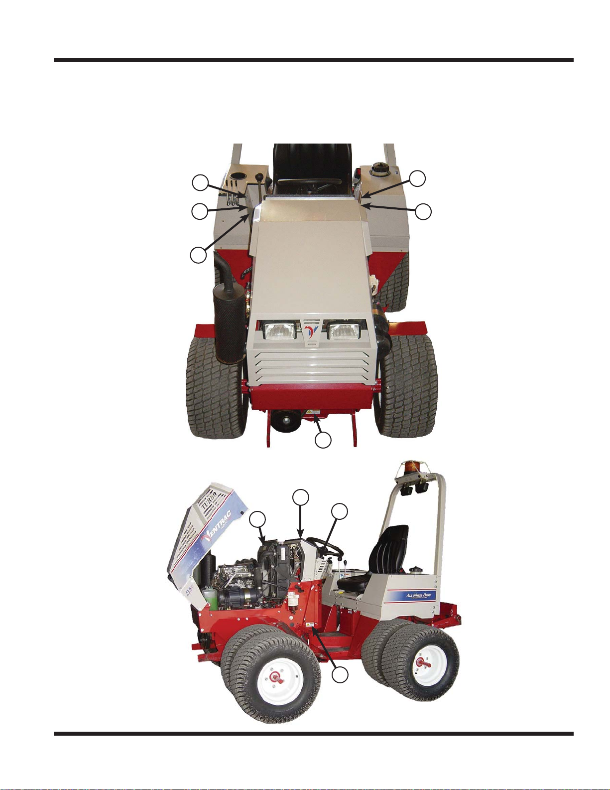
SAFETY
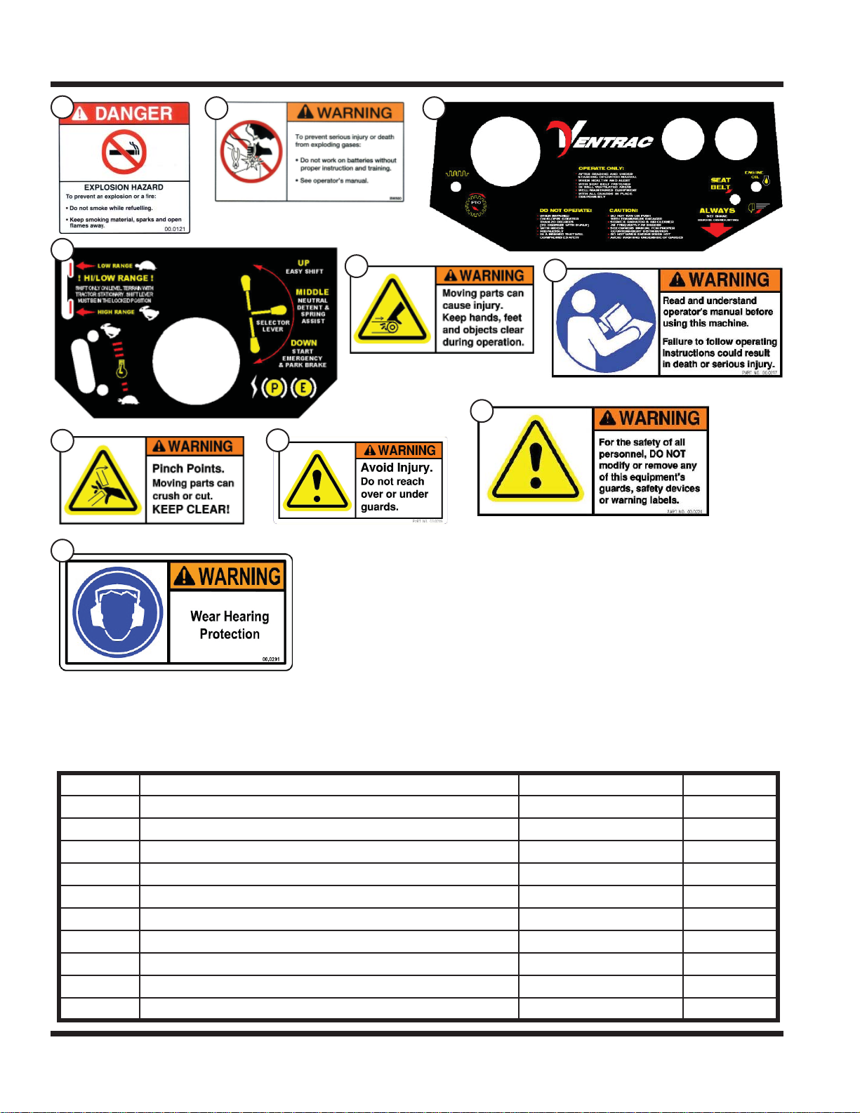
Safety Decals
The following safety decals must be maintained on your Ventrac 4200 power unit.
Keep all safety decals legible. Remove all grease, dirt, and debris from safety decals and instructional
labels. If any decals are faded, illegible, or missing, contact your dealer promptly for replacements.
When new components are installed, be sure that current safety decals are affi xed to the replacement
components.
A
F
I
J
B
E
C
D
H
G
Safety - 9
C
F
E
B
A
A
D
I
H
G
J
D
G
SAFETY
B
E
H
C
F
I
J
Decal Description Part Number Quantity
A Danger, Explosion Hazard 00.0121 1
B Warning - Battery Gases 00.0124 1
C Upper Dash - General Safety 00.0175 1
D Lower Dash - High/Low Shift Safety 00.0176 1
E Warning - Moving Parts 00.0216 1
F Warning - Read Owners Manual 00.0217 1
G Warning - Pinching Points 00.0218 2
H Warning - Avoid Injury 00.0219 1
I Warning - Safety Alteration 00.0220 1
J Warning - Hearing PPE 00.0291 1
Safety - 10
SAFETY
General Safety Procedures
for Ventrac Power Units, Attachments, & Accessories
Training Required
• The owner of this machine is solely responsible for properly training the operators.
• The owner/operator is solely responsible for the operation of this
machine and prevention of accidents or injuries occurring to him/herself, other people, or property.
• Do not allow operation or service by children or untrained personnel.
Local regulations may restrict the age of the operator.
• Before operating this machine, read the operator’s manual and understand its contents.
• If the operator of the machine cannot understand this manual, then it
is the responsibility of this machine’s owner to fully explain the material
within this manual to the operator.
• Learn and understand the use of all controls.
• Know how to stop the power unit and all attachments quickly in the event of an emergency.
Personal Protective Equipment Requirements
It is the responsibility of the owner to be sure that the operators use the proper personal protective equipment while operating the machine. Required personal protective equipment includes, but is not limited to,
the following list.
• Wear a certifi ed ear protection device to prevent loss of hearing.
• Prevent eye injury by wearing safety glasses while operating the machine.
• Closed toe shoes must be worn at all times.
• Long pants must be worn at all times.
• When operating in dusty conditions, it is recommended that a dust mask be worn.
Operating Safely
• Inspect machine before operation. Repair or replace any damaged, worn, or missing parts. Be sure
guards and shields are in proper working condition and are secured in place. Make all necessary
adjustments before operating machine.
• Some pictures in this manual may show shields or covers opened or removed in order to clearly illustrate
any instructions. Under no circumstance should the machine be operated without these devices in place.
• Alterations or modifi cations to this machine can reduce safety and could cause damage to the machine.
Do not alter safety devices or operate with shields or covers removed.
• Before each use, verify that all controls function properly and inspect all safety devices. Do not operate
if controls or safety devices are not in proper working condition.
• Check parking brake function before operating. Repair or adjust parking brake if necessary.
• Observe and follow all safety decals.
• All controls are to be operated from the operator’s seat only.
• Always wear a seat belt if the machine has a roll cage/bar installed.
• Ensure the attachment or accessory is locked or fastened securely to the power unit before operating.
• Ensure that all bystanders are clear of the power unit and attachment before operating. Stop machine if
someone enters your work area.
• Always be alert to what is happening around you, but do not lose focus on the task you are performing.
Always look in the direction the machine is moving.
• Look behind and down before backing up to be sure of a clear path.
• If you hit an object, stop and inspect the machine. Make all necessary repairs before operating machine again.
• Stop operation immediately at any sign of equipment failure. An unusual noise can be a warning of equipment
failure or a sign that maintenance is required. Make all necessary repairs before operating machine again.
Safety - 11
SAFETY
General Safety Procedures
for Ventrac Tractors, Attachments, & Accessories
Operating Safely (continued)
• If equipped with a high/low range feature, never shift between high and low range while on a slope.
Always move the machine to level ground and place the selector lever in park before shifting range.
• Do not leave machine unattended while it is running.
• Always park the machine on level ground.
• Always shut off engine when connecting attachment drive belt to the power unit.
• Never leave the operator’s seat without lowering the attachment to the ground, setting the parking
brake, shutting off the engine, and removing the ignition key. Make sure all moving parts have come to
a complete stop before dismounting.
• Never leave equipment unattended without lowering the attachment to the ground, setting the parking
brake, shutting off the engine, and removing the ignition key.
• Only operate in well-lit conditions.
• Do not operate when there is a risk of lightning.
• Never direct the discharge of any attachment in the direction of people, buildings, animals, vehicles, or
other objects of value.
• Never discharge material against a wall or obstruction. Material may ricochet back towards the operator.
• Use extra caution when approaching blind corners, shrubs, trees, or other objects that may obscure vision.
• Do not run the engine in a building without adequate ventilation.
• Do not touch the engine or the muffl er while the engine is running or immediately after stopping the engine.
These areas may be hot enough to cause a burn.
• Do not change the engine governor settings or over-speed the engine. Operating engine at excessive speed
may increase the hazard of personal injury.
• To reduce the hazard of fi re, keep the battery compartment, engine, and muffl er areas free of grass, leaves,
and excessive grease.
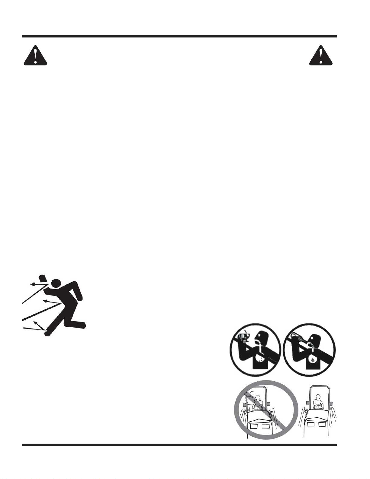
Preventing Accidents
• Clear working area of objects that might be hit or thrown from machine.
• Keep people and pets out of mowing area.
• Know the work area well before operation. Do not operate where traction or
stability is questionable.
• Reduce speed when you are operating over rough ground.
• Equipment can cause serious injury and/
or death when improperly used. Before
operating, know and understand the
operation and safety of the power unit
and the attachment being used.
• Do not operate machine if you are not in good physical and
mental health, if you will be distracted by personal devices, or are
under the infl uence of any substance which might impair deci-
sion, dexterity, or judgment.
• Children are attracted to machine activity. Be aware of children and
do not allow them in the working area. Turn off the machine if a
child enters the work area.
Keep Riders Off
• Only allow the operator on the power unit. Keep riders off.
• Never allow riders on any attachment or accessory.
Safety - 12
SAFETY
General Safety Procedures
for Ventrac Tractors, Attachments, & Accessories
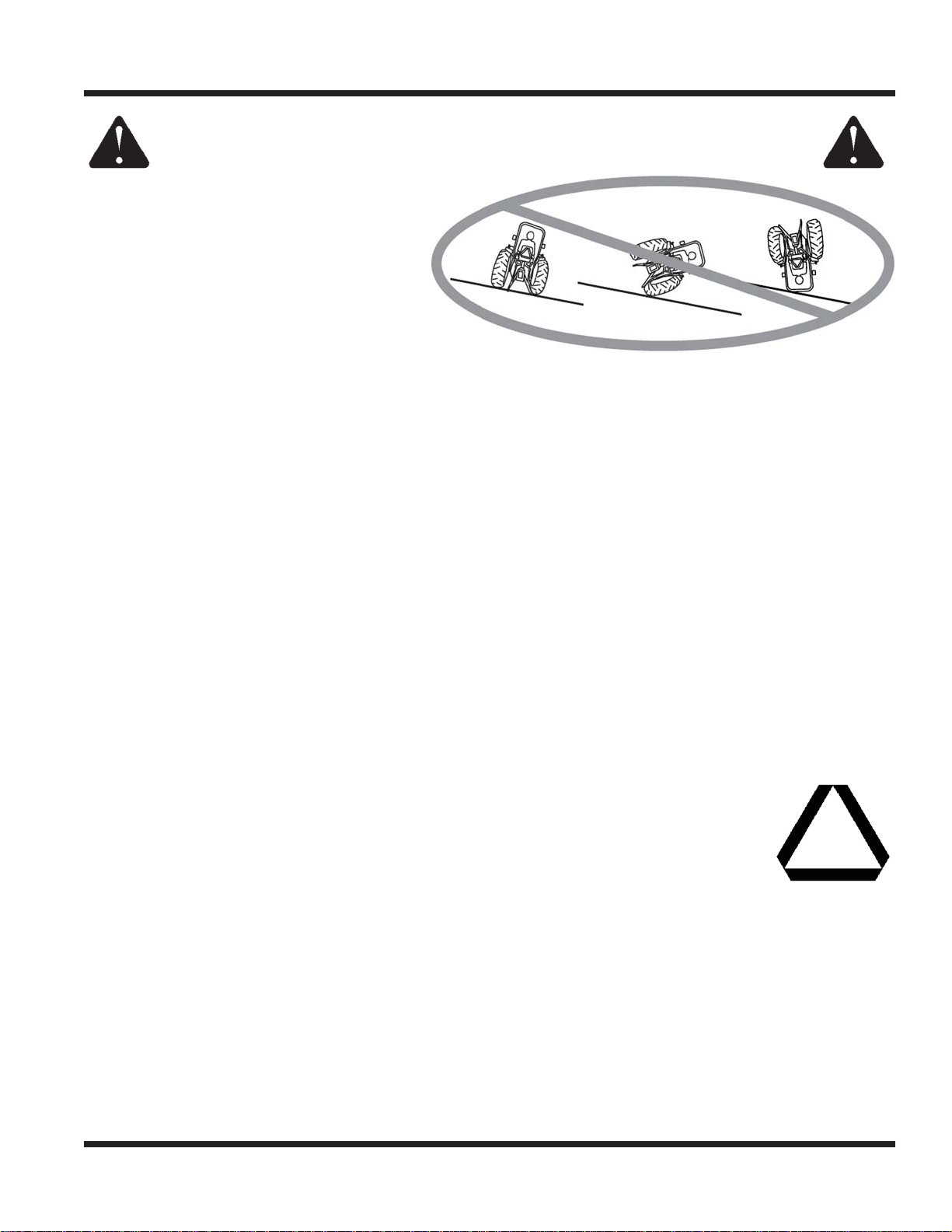
Operating On Slopes
• Slopes can cause loss-of-control and
tip-over accidents, which can result in
severe injury or death. Be familiar with the
emergency parking brake, along with the
power unit controls and their functions.
• If power unit is equipped with a fold down
roll bar, it must be locked in the upright
position when operating on any slope.
• Use low range (if equipped) when operating
on slopes greater than 15 degrees.
• Do not stop or start suddenly when operating on slopes.
• Never shift between high and low range while on a slope. Always move the power unit to level ground
and engage the parking brake before shifting range or placing the power unit in neutral.
• Variables such as wet surface and loose ground will reduce the degree of safety. Do not drive where
machine could lose traction or tip over.
• Keep alert for hidden hazards in the terrain.
• Stay away from drop-offs, ditches, and embankments.
• Sharp turns should be avoided when operating on slopes.
• Pulling loads on hills decreases safety. It is the responsibility of the owner/operator to determine loads
that can safely be controlled on slopes.
• Transport machine with attachment lowered or close to the ground to improve stability.
• While operating on slopes, drive in an up and down direction when possible. If turning is necessary
while driving across slopes, reduce speed and turn slowly in the downhill direction.
• Assure a suffi cient supply of fuel for continuous operation. A minimum of one-half tank of fuel is recommended.
Roadway Safety
• Operate with safety lights when operating on or near roadways.
• Obey all state and local laws concerning operation on roadways.
• Slow down and be careful of traffi c when operating near or crossing roadways. Stop before crossing
roads or sidewalks. Use care when approaching areas or objects that may obscure vision.
• If there is doubt of safety conditions, discontinue machine operation until a time when
operation can be performed safely.
• When operating near or on roadways, have a Slow Moving Vehicle Emblem clearly
displayed.
Truck Or Trailer Transport
• Use care when loading or unloading machine into a truck or trailer.
• The parking brake is not suffi cient to lock the machine during transport. Always secure the power unit
and/or attachment to the transporting vehicle.
• Shut off fuel supply to power unit during transport on truck or trailer.
• If equipped, turn the battery disconnect switch to the Off position to shut off electrical power.
Safety - 13

SAFETY
General Safety Procedures
for Ventrac Tractors, Attachments, & Accessories
Maintenance
• Keep all safety decals legible. Remove all grease dirt, and debris from safety decals and instructional labels.
• If any decals are faded, illegible, or missing, contact your dealer promptly for replacements.
• When new components are installed, be sure that current safety decals are affi xed to the replacement
components.
• If any component requires replacement, use only original Ventrac replacement parts.
• Always disconnect the negative battery cable from the battery when working with electrical components.
• Keep all bolts, nuts, screws, and other fasteners properly tightened.
• Always lower the attachment to the ground, engage parking brake, shut off engine, and remove the
ignition key. Make sure all moving parts have come to a complete stop before cleaning, inspection,
adjusting or repairing.
• If the power unit, attachment, or accessory requires repairs or adjustments not instructed in the operator’s
manual, the power unit, attachment, or accessory must be taken to an authorized Ventrac dealer for service.
• Never perform maintenance on the power unit and/or attachment if someone is sitting in the operator’s seat.
• Always use protective glasses when handling the battery.
• Check all fuel lines for tightness and wear on a regular basis. Tighten or repair them as needed.
• To reduce the hazard of fi re, keep the battery compartment, engine, and muffl er areas free of grass,
leaves, and excessive grease.
• Do not touch the engine or the muffl er while the engine is running or immediately after stopping the
engine. These areas may be hot enough to cause a burn.
• Do not change the engine governor settings or over-speed the engine. Operating engine at excessive
speed may increase the hazard of personal injury.
• Springs may contain stored energy. Use caution when disengaging or removing springs and/or spring
loaded components.
• An obstruction or blockage in a drive system or moving/rotating parts may cause a buildup of stored
energy. When the obstruction or blockage is removed, the drive system or moving/rotating parts may
move suddenly. Do not attempt to remove an obstruction or blockage with your hands. Keep hands,
feet, and clothing away from all power-driven parts.
• Dispose of all fl uids in accordance with local laws.
Fuel Safety
• Do not refuel machine while smoking or at a location near fl ames or sparks.
• Always refuel the machine outdoors.
• Do not store machine or fuel container indoors where fumes or fuel can reach an open
fl ame, spark, or pilot light.
• Only store fuel in an approved container. Keep out of reach of children.
• Never remove fuel cap or add fuel with the engine running. Allow engine to cool before refueling.
• Never remove fuel cap while on a slope. Only remove when parked on a level surface.
• Replace all fuel tank and container caps securely.
• Do not overfi ll fuel tank. Only fi ll to bottom of fuel neck, do not fi ll fuel neck full. Overfi lling of fuel tank
could result in engine fl ooding or fuel leakage from the tank.
• If fuel is spilled, do not attempt to start the engine. Move the power unit away from the fuel spill and
avoid creating any source of ignition until fuel vapors have dissipated.
• If the fuel tank must be drained, it should be drained outdoors into an approved container.
• Dispose of all fl uids in accordance with local laws.
• Check all fuel lines for tightness and wear on a regular basis. Tighten or repair them as needed.
• The fuel system is equipped with a shut-off valve. Shut off the fuel when transporting the machine to
and from the job, when parking the machine indoors, or when servicing the fuel system.
Safety - 14
SAFETY
General Safety Procedures
for Ventrac Tractors, Attachments, & Accessories
Hydraulic Safety
• Make sure all hydraulic connections are tight and all hydraulic hoses and tubes are in good condition.
Repair any leaks and replace any damaged or deteriorated hoses or tubes before starting the machine.
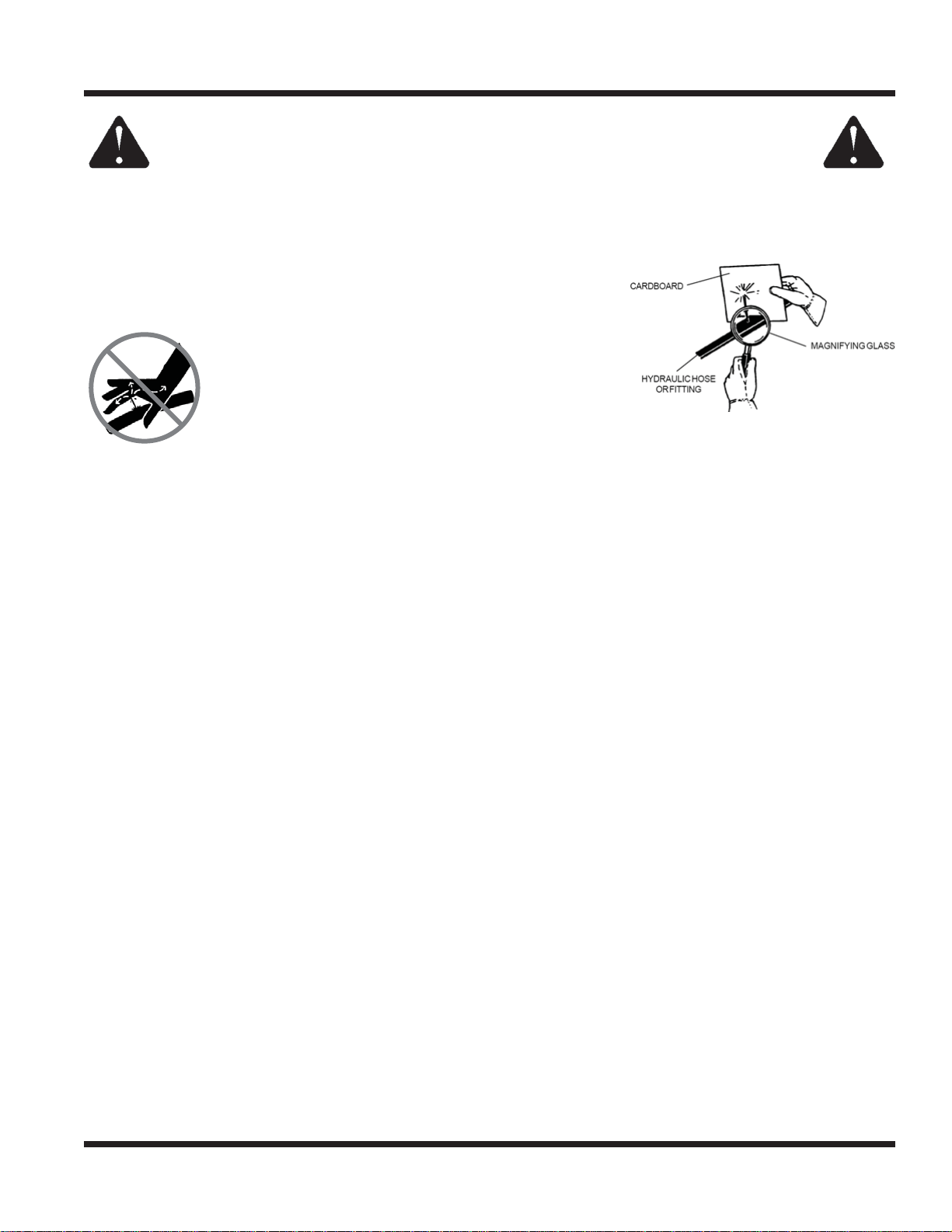
• Hydraulic leaks can occur under high pressure. Hydraulic leaks require special care and attention.
• Use a piece of cardboard and a magnifying glass to locate sus-
pected hydraulic leaks.
• Keep body and hands away from pinhole leaks
or nozzles that eject high pressure hydraulic
fl uid. Hydraulic fl uid escaping under high pres-
sure can penetrate the skin causing serious
injury. If hydraulic fl uid is injected into skin, seek
immediate medical attention.
• Hydraulic system may contain stored energy. Before performing maintenance or repairs on the hydraulic
system, remove attachments, engage parking brake, disengage weight transfer system (if equipped), shut
off engine, and remove ignition key. To relieve pressure on the auxiliary hydraulic system, shut off the power
unit engine and move the secondary S.D.L.A. lever left and right before disconnecting the auxiliary hydraulic
quick couplers.
• Dispose of all fl uids in accordance with local laws.
Safety - 15
SAFETY
KT4200 Safety Procedures
• Weight transfer springs may contain stored energy. Always disengage the weight transfer system before
performing maintenance or repairs on the weight transfer system, the front hitch, or the lift hydraulics.
• Power unit hydraulic system may contain stored energy. Before performing maintenance or repairs on
the attachment hydraulic system, remove attachments, engage parking brake, disengage weight
transfer system, shut off engine, and remove ignition key.
CALIFORNIA PROPOSITION 65
Diesel Exhaust Warning
The engine exhaust from this product contains
chemicals known to the State of California to cause
cancer, birth defects or other reproductive harm.
CALIFORNIA PROPOSITION 65
Battery Warning
Battery posts, terminals, and related accessories contain lead and lead
compounds, chemicals known to the State of California to cause cancer
and reproductive harm. Wash hands after handling!
Diesel engine exhaust and some of it’s
constituents are known to the State of
California to cause cancer, birth defects or
other reproductive harm.
Roll-Over Protective Structure
Your power unit is equipped with a Roll-Over Protective Structure (ROPS).
• Certifi ed seat belt anchor: #OSHA 1928.51.
• Certifi ed ROPS, roll bar: #OSHA 1928.52.
• Certifi ed ROPS, fold down roll bar: #OSHA 1928-51.
• Fold down ROPS must be fi xed in the upright position during operation.
• Always wear the seat belt during operation. Never jump from the power unit.
• During operation, the seat belt indicator light on the dash will turn on if the seat belt is not fastened.
The seat belt indicator light will turn off if the seat belt is fastened.
• If damaged, the roll bar or seat belt must be replaced before operation.
Alterations or modifi cations to this machine can
reduce safety and could cause damage to the
machine. Do not alter safety devices or operate
with shields or covers removed.
Safety - 16
 Loading...