

Ventrac 3400Y, 3400L Operator's Manual

Operator’s Manual
3400Y
Serial Number 3400Y-AK01001 --
Original Operator’s Manual
VENTRAC.COM
Revised 12/06/18
09.10087 Rev. 10
View all manuals
Visit ventrac.com/manuals
500 Venture Drive
Orrville Oh 44667
www.ventrac.com
for the latest version of this
operator’s manual.
A downloadable parts manual
is also available.
To the Owner
Contact Information and Product Identication
If you need to contact an authorized Ventrac dealer for information on servicing your product,
always provide the product model and serial numbers.
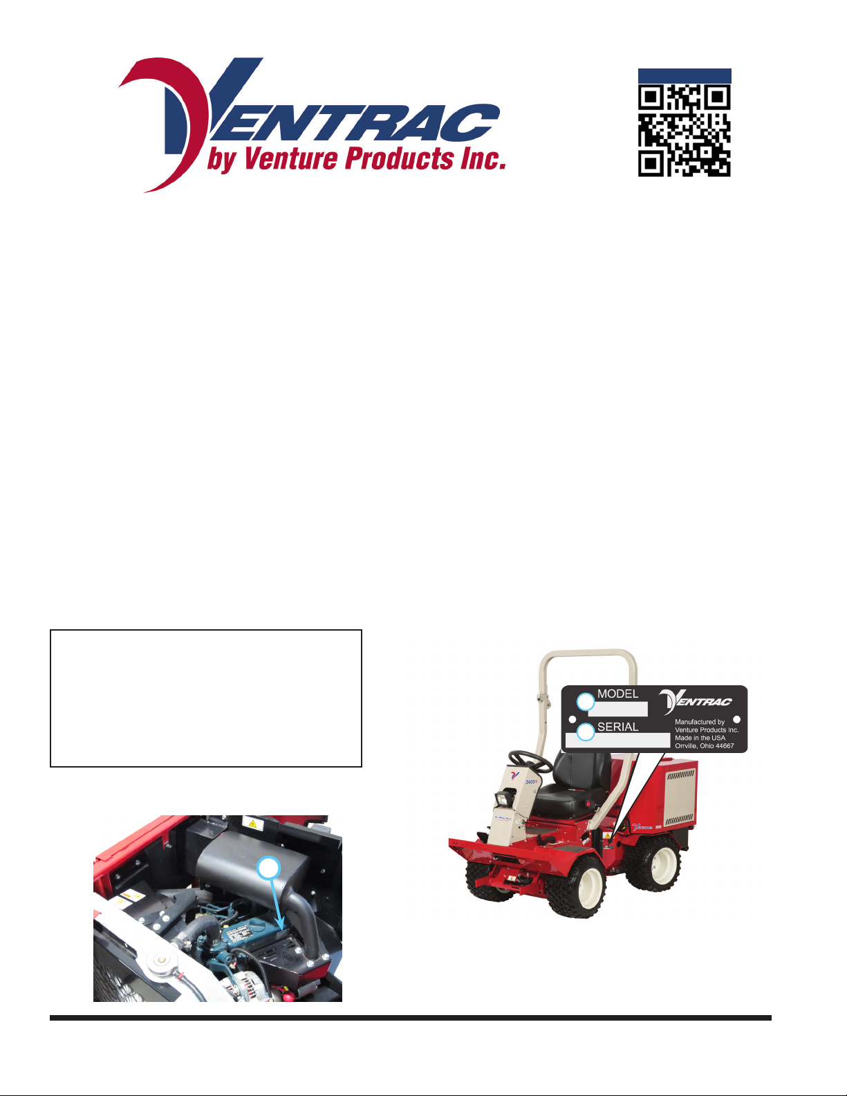
Please ll in the following information for future reference. See the picture(s) below to nd the
location of the identication numbers. Record them in the spaces provided.
Date of Purchase: __________________________________________________________________
Dealer: ___________________________________________________________________________
Dealer Address: ____________________________________________________________________
____________________________________________________________________
Dealer Phone Number: ______________________________________________________________
Dealer Fax Number: ________________________________________________________________
Model # (A): ___________________________
Serial # (B): ____________________________
A
B
Afx Part/Serial Number label here.
Engine Serial # (C) _________________________
C
Venture Products Inc. reserves the right to make changes
in design or specications without obligation to make like
changes on previously manufactured products.
2

TABLE OF CONTENTS
INTRODUCTION PAGE 7
Product Description ................................................................................................................................ 8
Why Do I Need an Operator’s Manual? ................................................................................................. 8
Using Your Manual ................................................................................................................................. 9
Manual Glossary ....................................................................................................................................9
SAFETY PAGE 10
Safety Decals ....................................................................................................................................... 10
General Safety Procedures .................................................................................................................. 13
Training Required .................................................................................................................................13
Personal Protective Equipment Requirements ....................................................................................13
Operation Safety ..................................................................................................................................13
Preventing Accidents ............................................................................................................................14
Keep Riders O .................................................................................................................................... 14
Operating On Slopes ............................................................................................................................15
Roadway Safety ................................................................................................................................... 15
Truck Or Trailer Transport ....................................................................................................................15
Maintenance ......................................................................................................................................... 16
Fuel Safety ........................................................................................................................................... 16
Hydraulic Safety ................................................................................................................................... 17
3400 Safety Procedures .......................................................................................................................17
Operator Platform Access .................................................................................................................... 17
Roll Over Protective Structure (ROPS) ................................................................................................ 18
3400 Safety Procedures .......................................................................................................................18
Operator Safety Interlock System ........................................................................................................19
OPERATIONAL CONTROLS PAGE 20
Standard Operational Control Locations .............................................................................................. 20
Optional Operational Control Locations ...............................................................................................21
RPM/Hour Cluster Gauge (A) ..............................................................................................................22
Fuel Cluster Gauge (B) ........................................................................................................................22
Ignition Switch (C) ................................................................................................................................ 22
Warning Alarm (D) ................................................................................................................................ 22
Steering Wheel (E) ............................................................................................................................... 23
Steering Tilt Adjustment Lever (F) ........................................................................................................23
Front Hitch Latch Lever (G) ..................................................................................................................23
Weight Transfer Select Lever (H) ......................................................................................................... 23
Circuit Breaker & Battery Disconnect (I) ..............................................................................................23
Seat Belt (J) .........................................................................................................................................23
Fuel Shut-o Valve (K) .........................................................................................................................23
SDLA Control Levers (L & M) ...............................................................................................................24
Foot Pedal (N) ...................................................................................................................................... 24
Selector Lever/Parking Brake(O) .........................................................................................................24
Auxiliary Hydraulic Quick Couplers (P) ................................................................................................25
Power Take O (PTO) Switch (R) ........................................................................................................25
Headlight Switch (S) .............................................................................................................................25
3

TABLE OF CONTENTS
OPERATIONAL CONTROLS (Continued)
Throttle Lever (T) .................................................................................................................................25
Seat Latch Strap (U) ............................................................................................................................25
Transmission Neutral Levers (V) ..........................................................................................................25
Horn Switch (AA) .................................................................................................................................. 25
Directional Signal Switch (BB) .............................................................................................................25
Hazard Flasher Switch (CC) ................................................................................................................26
Work Light Switch (DD) ........................................................................................................................26
Strobe Light Switch (EE) ...................................................................................................................... 26
12 Volt Rear Switches & 4-Pin Socket (FF, GG, & HH) ........................................................................26
12 Volt Front Switches & 4-Pin Socket (RR, SS, & TT) .......................................................................26
Front Hitch Valve (MM) ........................................................................................................................26
GENERAL OPERATION PAGE 27
Daily Inspection .................................................................................................................................... 27
Starting The Engine .............................................................................................................................27
Forward And Reverse .......................................................................................................................... 28
Stopping The Power Unit .....................................................................................................................28
Shutting O The Engine .......................................................................................................................28
Attaching ..............................................................................................................................................28
Detaching ............................................................................................................................................. 29
Operating Attachments .........................................................................................................................29
Front Hitch ............................................................................................................................................ 29
PTO Drive Belt & Pulley .......................................................................................................................29
Front Auxiliary Couplers ....................................................................................................................... 29
Weight Transfer .................................................................................................................................... 30
Roll-Over Protection System (ROPS) ..................................................................................................30
12 Volt 4-Pin Auxiliary Outlets (Optional Accessory) ............................................................................ 30
Operating On Slopes ............................................................................................................................31
Operation in Water, Mud, Snow, or Ice ................................................................................................31
Towing Or Pushing The Power Unit .....................................................................................................31
SERVICE PAGE 32
Service And General Maintenance .......................................................................................................32
Cleaning And Appearance Care ........................................................................................................... 32
Service Access Points .......................................................................................................................... 33
Checking Hydraulic Oil Level ...............................................................................................................34
Changing Hydraulic Oil Filter ...............................................................................................................35
Changing Hydraulic Oil ........................................................................................................................35
Changing Rear Transaxle Dierential Oil ............................................................................................. 36
Checking Engine RPM ......................................................................................................................... 36
Checking Engine Oil Level ................................................................................................................... 37
Changing Engine Oil And Filter ............................................................................................................ 37
Inspecting & Resetting The Air Filter Restriction Gauge ...................................................................... 38
Changing Air Filter Elements ................................................................................................................39
Filling The Fuel Tank ............................................................................................................................39
4

TABLE OF CONTENTS
SERVICE (Continued)
Servicing The Fuel Filter/Water Separator ........................................................................................... 40
Changing The Fuel Filter ......................................................................................................................40
Priming The Fuel System .....................................................................................................................40
Checking The Fan (Alternator) Belt ......................................................................................................40
Adjusting Fan (Alternator) Belt Tension ................................................................................................41
Cleaning Engine Compartment & Engine ............................................................................................41
Servicing The Cooling System .............................................................................................................41
Checking The Cooling System .............................................................................................................42
Cleaning The Radiator And Screen ...................................................................................................... 42
Draining The Cooling System ..............................................................................................................43
Servicing The Battery ........................................................................................................................... 44
Removing The Battery .........................................................................................................................44
Installing The Battery ...........................................................................................................................44
Cleaning The Battery And Terminals .................................................................................................... 45
Charging The Battery ........................................................................................................................... 45
Jump Starting Procedure .....................................................................................................................45
TCM (Tractor Control Module) Explanation .........................................................................................46
Replacing Fuses (Power Relay Module) .............................................................................................. 46
Replacing Fuses (Front Fuse Panel) ...................................................................................................46
Replacing Fuses (Rear Fuse Panel) .................................................................................................... 47
Replacing Fuses (Engine) .................................................................................................................... 47
Switching Speedometer (MPH or Km/H) ..............................................................................................48
Replacing Light Bulbs (Headlights) ...................................................................................................... 48
Replacing The Taillights ....................................................................................................................... 48
Replacing the Work Lights ...................................................................................................................48
Replacing The Turn Signal Lights ........................................................................................................48
Replacing The Strobe Light Bulb .........................................................................................................48
Drive Belt Inspection ............................................................................................................................49
Engine Drive Belt Inspection & Adjustment .......................................................................................... 49
Engine Drive Belt Replacement ...........................................................................................................50
PTO Belt Replacement ........................................................................................................................50
Transaxle Drive Belt Replacement .......................................................................................................51
Clutch Air Gap Inspection & Adjustment .............................................................................................. 52
Wheel Removal & Installation ..............................................................................................................52
Tire Pressure ........................................................................................................................................52
ROPS And Seat Belt Inspection ........................................................................................................... 53
Parking Brake Inspection & Adjustment ............................................................................................... 53
Neutral Adjustment ............................................................................................................................... 54
Storage ................................................................................................................................................. 54
Maintenance Schedule .........................................................................................................................56
Maintenance Checklist ......................................................................................................................... 57
Ventrac Maintenance Log ....................................................................................................................58
5

TABLE OF CONTENTS
TROUBLESHOOTING PAGE 61
Wiring Diagram Reference Key ............................................................................................................61
Wiring Diagram - Rear Harness ........................................................................................................... 62
Wiring Diagram - Front Harness ..........................................................................................................63
Wiring Diagram Engine Harness .......................................................................................................... 64
Wiring Diagram - Optional 30.0219 4-Pin Female Socket & 30.0218 4-Pin Male Plug........................65
Electrical Troubleshooting Using The Tractor Control Module (TCM) ..................................................66
Electrical Troubleshooting Guide .........................................................................................................68
Engine .................................................................................................................................................. 69
Electrical ............................................................................................................................................... 70
Hydraulic ..............................................................................................................................................71
Power Unit ............................................................................................................................................ 71
SPECIFICATIONS PAGE 72
Engine .................................................................................................................................................. 72
Electrical ............................................................................................................................................... 72
Power Train ..........................................................................................................................................72
Controls & Instrument Panel ................................................................................................................72
Other Features ..................................................................................................................................... 72
Dimensions ..........................................................................................................................................73
Fluid Capacities & Specications ......................................................................................................... 73
Amperage Draw Chart .........................................................................................................................74
Belt Chart .............................................................................................................................................74
WARRANTY PAGE 75
6
INTRODUCTIONINTRODUCTION
enture Products Inc. is pleased to provide you with your new
V
Ventrac power unit! We hope that Ventrac equipment will
provide you with a ONE Tractor Solution.
Listed below are just some of the items that can provide you
versatility as you use your 3400. Please visit our web site, or
contact your authorized Ventrac dealer for a complete list of
items available for your new power unit.
Item Description
12 Volt Front Kit 70.3036
12 Volt Rear Kit 70.3050
Backup Alarm Kit 70.3037
Directional / Hazard Signal Kit 70.3046
ES220 Spreader 39.55500
Front Hitch Valve Kit 70.3042
Horn Kit 70.3041
Accessories
Rear Weight Bracket Kit 70.3043
Item Description
Aerator with Open Spoon Tine 39.55490
Aerator with Slitter/Slicer Tine 39.55492
Aerator with Coring Tine 39.55494
Blade - 48” 39.55251
Blade - 60” 39.55252
Blower 39.35445
Broom 39.35402
Edger 39.55332
Attachments
Field Mower - 45” 39.35102
Finish Mower - 52” 39.35100
Finish Mower - 60” 39.35101
Part Number
Part Number
Item Description
Strobe Light Kit 70.3045
Suspension Seat 70.3040
Trailer Mover Hitch 70.2016
Weather Cab 70.2015
Work Light Kit 70.3044
Dual Hydraulic Auxiliary Kit 70.3039
Accessories
Item Description
Rear Discharge Mower - 52” 39.35107
Power Bucket - 30” 39.55213
Power Bucket - 48” 39.55214
Snow Blower 39.35427
Stump Grinder 39.35300
Terra Rake - 52” 39.55431
V-Blade 39.55271
Attachments
Part Number
Part Number
Introduction - 7

INTRODUCTION
Product Description
The Ventrac 3400 is a unique All Wheel Drive power unit that distributes its power to four equal size otation tires to provide excellent control, traction, stability, maneuverability, and braking. Its innovative, patented Tandem Drive Train is coupled with an articulating and oscillating, uni-body frame to create a power
unit with quiet, ecient, and powerful performance. The 3400 is equipped with power steering and has a
turning radius of 28 inches (71 cm), allowing it to maneuver in and around tight places with ease.
The 3400 is designed with the operator seated at the front of the power unit for unobstructed visibility of
attachments and terrain ahead. This design uses a rear mounted engine that keeps heat, exhaust, and
noise behind the operator.
Ventrac’s patented SDLA control, located next to the operator, allows for easy control of Speed, Direction,
Lift, and Auxiliary functions with one hand.
The Ventrac attachment mount system allows the operator to change front mounted attachments quickly
and eciently.
Standard features of the 3400 power unit include:
• a fold down roll bar.
• a wire harness that is pre-wired for optional accessories.
• a complete electrical system circuit breaker and battery disconnect.
• a computer controlled onboard diagnostic system for the electrical circuits.
• two cluster gauges on the steering column. One gauge includes a fuel gauge, speedometer, glow
plug indicator, parking brake indicator, PTO ‘On’ indicator, and a low fuel indicator. The second gauge
includes an engine temperature gauge, hour meter / tachometer, and warning lights for high engine
coolant temperature, low engine oil pressure, and low battery voltage. All of the warning indicator lights
also trigger an audible alarm to insure the operator is aware of an unsafe condition.
Why Do I Need an Operator’s Manual?
This manual has been created to help you gain the important knowledge of what is needed to safely
operate, maintain, and service your machine. It is divided into sections for convenient reference of the
appropriate section.
You must read and understand the operator’s manual for each piece of Ventrac equipment you own. Reading the operator’s manual will help you become familiar with each specic piece of equipment. Understanding the operator’s manual will help you, as well as others, avoid personal injury and/or damage to the
equipment. Keep this manual with the machine at all times. The manual should remain with the machine
even if it is sold. If this manual becomes damaged or unreadable, it should be replaced immediately. Contact your local Ventrac dealer for a replacement.
When using a Ventrac attachment, be sure to read and follow the safety and operating instructions of both
the power unit and the attachment being used to ensure the safest operation possible.
The information in this manual provides the operator with the safest procedures to operate the machine
while getting the maximum use out of the unit. Failure to follow the safety precautions listed in this manual
may result in personal injury and/or damage to the equipment.
Introduction - 8
INTRODUCTION
Using Your Manual
Throughout this manual, you will encounter special messages and symbols that identify potential safety
concerns to help you as well as others avoid personal injury or damage to the equipment.
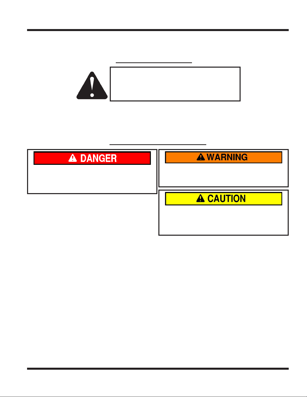
SYMBOL DEFINITIONS
ATTENTION
This symbol identies potential health and
safety hazards. It marks safety precautions.
Your safety and the safety of others is involved.
There are three signal words that describe the level of safety concern: Danger, Warning, and Caution.
Safety should always be the #1 priority when working on or operating equipment. Accidents are more likely
to occur when proper operating procedures are not followed or inexperienced operators are involved.
Note: Right-Hand and Left-Hand orientations may be referred to at dierent places throughout this manual.
Right-Hand and Left-Hand is determined as if sitting on the power unit seat facing forward.
SIGNAL WORD DEFINITIONS
Indicates an imminently hazardous situation
which, if not avoided, will result in death or
serious injury. This signal word is limited to the
most extreme cases.
Indicates a potentially hazardous situation
which, if not avoided, could result in death or
serious injury.
Indicates a potentially hazardous situation
which, if not avoided, may result in minor or
moderate injury and/or property damage. It may
also be used to alert against unsafe practices.
Manual Glossary
Power Unit A Ventrac tractor or other Ventrac engine powered device that may be operated by itself or
with an attachment or accessory.
Attachment A piece of Ventrac equipment that requires a Power Unit for operation.
Accessory A device that attaches to a Power Unit or Attachment to extend its capabilities.
Machine Describes any “Attachment” or “Accessory” that is used in conjunction with a power unit.
Introduction - 9
SAFETY
SAFETY
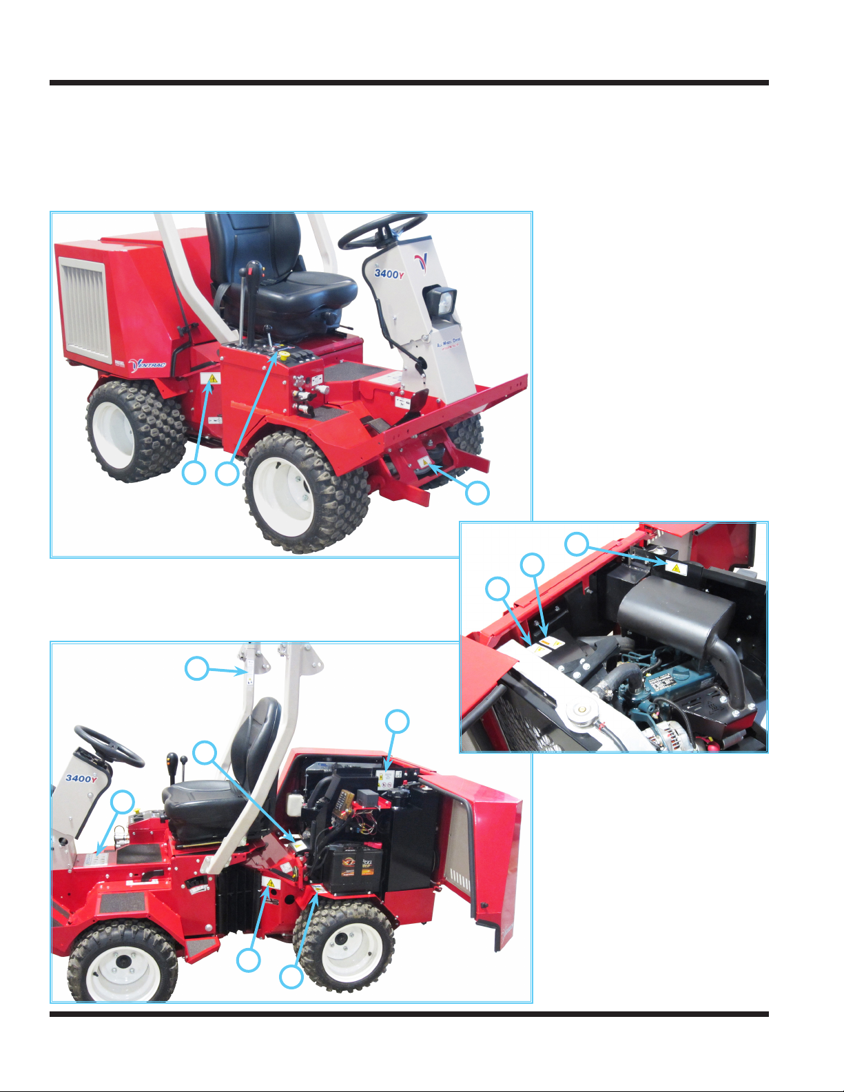
Safety Decals
The following safety decals must be maintained on your Ventrac 3400 power unit.
Keep all safety decals legible. Remove all grease, dirt, and debris from safety decals and instructional
labels. If any decals are faded, illegible, or missing, contact your dealer promptly for replacements.
When new components are installed, be sure that current safety decals are axed to the replacement
components.
G
C
A
B
H
J
H
F
D
C
C
E
Safety - 10
SAFETY
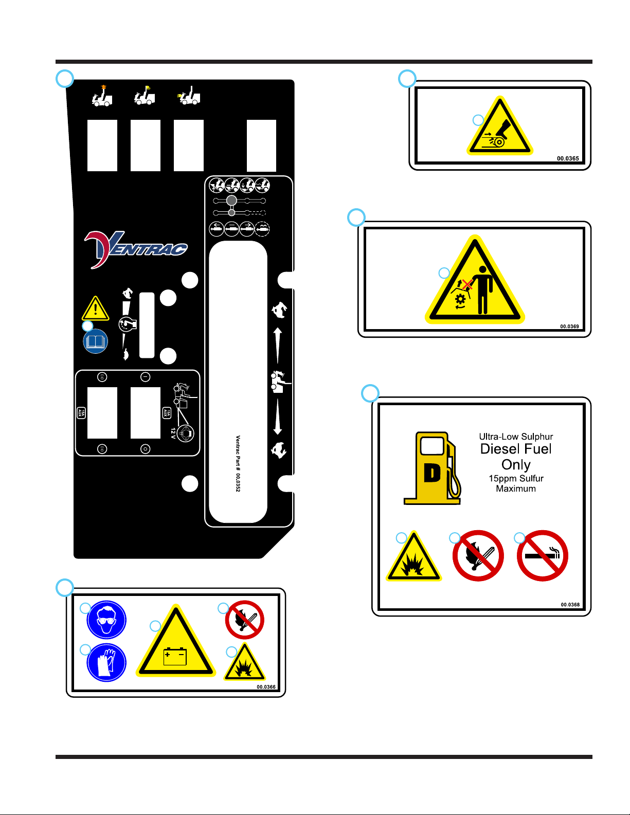
A B
C
1
1. Cutting / dismemberment / entanglement hazard -
Do not remove shields.
Stay away from moving parts.
1
1. Cutting / entanglement hazard Stay away from moving parts.
1
1. WARNING: Read operator’s manual.
E
2
1
3
D
1 2 3
4
1. DANGER: Explosion / re hazard.
2. Keep away from re, sparks, and pilot lights when
5
refueling or storing machine and fuel.
3. Smoking is prohibited.
1. DANGER: Battery acid is caustic and can cause chemical burns. Keep bystanders a safe distance from the battery.
2. Wear eye protection, such as goggles or a face shield, when checking or servicing batteries.
3. Wear appropriate protective gear, such as rubber gloves and an apron, when checking or servicing batteries.
4. Do not expose batteries to arcs, sparks, or open ames. Do not use smoking materials near batteries.
5. Explosion hazard - batteries produce ammable and explosive gases.
Safety - 11
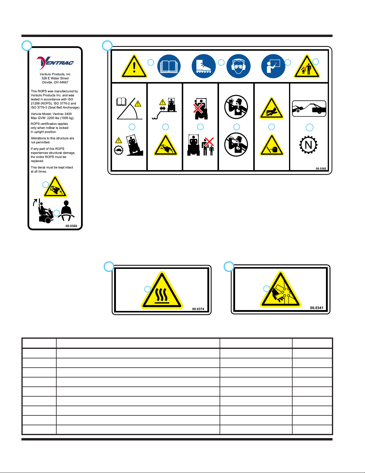
SAFETY
F
1
2
1. WARNING: Rollover!
2. Keep the roll bar in the raised
and locked position and keep
the seat belt securely fastened
during operation.
G
1 2 3
5 6 7 8 9
1. WARNING: Read operator’s manual.
2. Wear personal protective gear, such as safety glasses, closed toe shoes or boots, and ear protection.
3. Operators must receive training prior to operating the machine.
4. Do not operate with shields or guards removed.
5. WARNING: Read slope operation instructions. Slow down when operating on slopes. Keep the roll bar
in the raised and locked position and the seat belt securely fastened.
6. WARNING: Keep a safe distance from the edge of drop-os, ditches, and embankments. The machine
could roll over if a wheel drops over the edge or if the edge caves in.
7. Do not carry passengers. Stop the machine if someone enters the area.
8. Do not operate while under the inuence of drugs or alcohol.
9. WARNING: Hydraulic uid is under high pressure and can penetrate skin, causing injury. Keep hands,
face, and body away from pinholes or nozzles the eject hydraulic uid under high pressure.
10. When towing or pushing the power unit, the transaxles must be disengaged by moving the front and
rear axle neutral links to the neutral position or damage to the transaxles will result.
4
10
H
1
1. Hot surface hazard - Hot surfaces can cause sever
burns. Allow engine, exhaust components, and surrounding surfaces to cool before servicing.
J
1
1. Cutting / dismemberment / entanglement
hazard - Stay away from moving parts.
Decal Description Part Number Quantity
A Dash Side 00.0352 1
B Warning, Moving Parts 00.0365 1
C Warning, Do Not Remove Shields 00.0369 3
D Warning, Diesel Only 00.0368 1
E Warning, Battery 00.0366 1
F ROPS Certication 00.0360 1
G Warning, Operator Safety 00.0362 1
H Warning, Hot Surface 00.0374 2
J Warning, Fan 00.0341 1
Safety - 12
SAFETY
General Safety Procedures
for Ventrac Power Units, Attachments, & Accessories
Training Required
• The owner of this machine is solely responsible for properly training the operators.
• The owner/operator is solely responsible for the operation of this
machine and prevention of accidents or injuries occurring to him/herself, other people, or property.
• Do not allow operation or service by children or untrained personnel.
Local regulations may restrict the age of the operator.
• Before operating this machine, read the operator’s manual and understand its contents.
• If the operator of the machine cannot understand this manual, then it
is the responsibility of this machine’s owner to fully explain the material
within this manual to the operator.
• Learn and understand the use of all controls.
• Know how to stop the power unit and all attachments quickly in the event of an emergency.
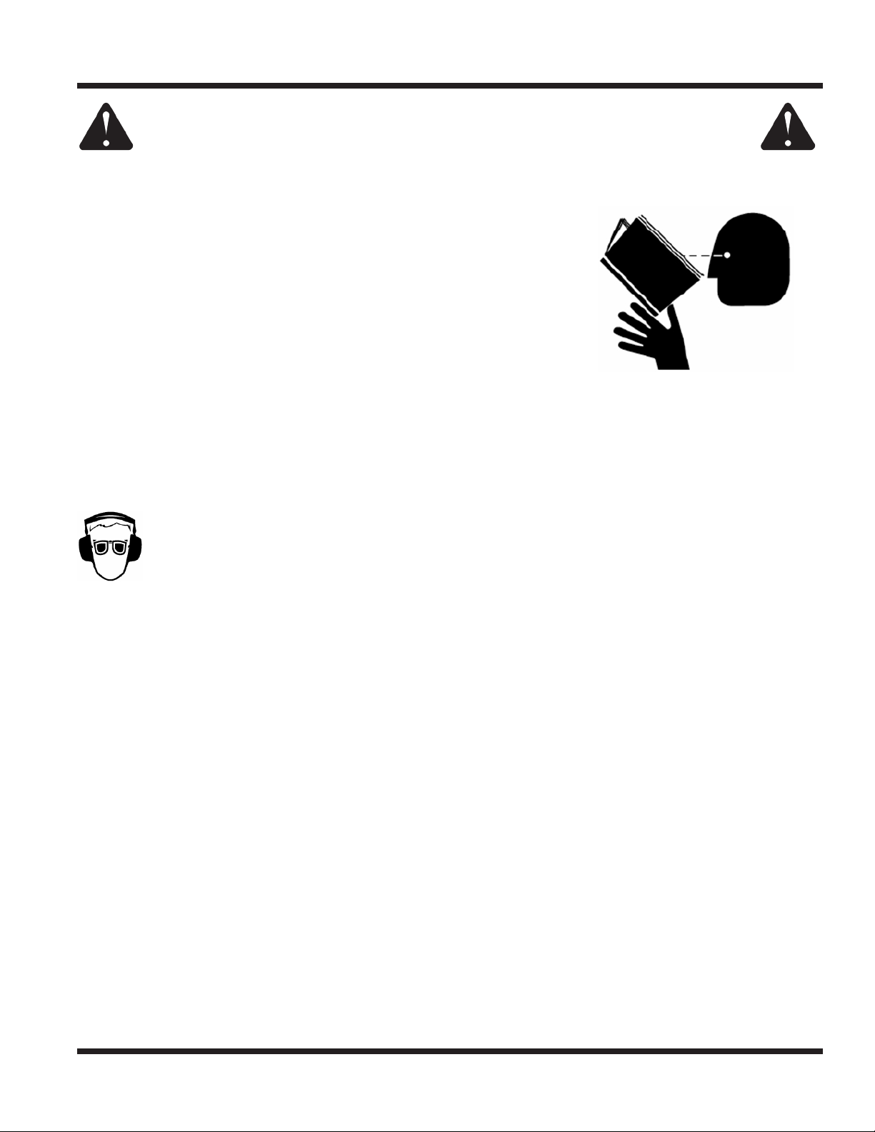
Personal Protective Equipment Requirements
It is the responsibility of the owner to be sure that the operators use the proper personal protective equipment while operating the machine. Required personal protective equipment includes, but is not limited to,
the following list.
• Wear a certied ear protection device to prevent loss of hearing.
• Prevent eye injury by wearing safety glasses while operating the machine.
• Closed toe shoes must be worn at all times.
• Long pants must be worn at all times.
• When operating in dusty conditions, it is recommended that a dust mask be worn.
Operation Safety
• Inspect machine before operation. Repair or replace any damaged, worn, or missing parts. Be sure
guards and shields are in proper working condition and are secured in place. Make all necessary
adjustments before operating machine.
• Some pictures in this manual may show shields or covers opened or removed in order to clearly illustrate
any instructions. Under no circumstance should the machine be operated without these devices in place.
• Alterations or modications to this machine can reduce safety and could cause damage to the machine.
Do not alter safety devices or operate with shields or covers removed.
• Before each use, verify that all controls function properly and inspect all safety devices. Do not operate
if controls or safety devices are not in proper working condition.
• Check parking brake function before operating. Repair or adjust parking brake if necessary.
• Observe and follow all safety decals.
• All controls are to be operated from the operator’s station only.
• Always wear a seat belt if the machine has a roll cage/bar installed and in upright position.
• Ensure the attachment or accessory is locked or fastened securely to the power unit before operating.
• Ensure that all bystanders are clear of the power unit and attachment before operating. Stop machine if
someone enters your work area.
• Always be alert to what is happening around you, but do not lose focus on the task you are performing.
Always look in the direction the machine is moving.
• Look behind and down before backing up to be sure of a clear path.
• If you hit an object, stop and inspect the machine. Make all necessary repairs before operating machine again.
• Stop operation immediately at any sign of equipment failure. An unusual noise can be a warning of equipment
failure or a sign that maintenance is required. Make all necessary repairs before operating machine again.
Safety - 13
SAFETY
General Safety Procedures
for Ventrac Power Units, Attachments, & Accessories
Operation Safety (continued)
• If equipped with a high/low range feature, never shift between high and low range while on a slope.
Always move the machine to level ground and engage the parking brake before shifting range.
• Do not leave machine unattended while it is running.
• Always park the machine on level ground.
• Always shut o engine when connecting attachment drive belt to the power unit.
• Never leave the operator’s station without lowering the attachment to the ground, setting the parking
brake, shutting o the engine, and removing the ignition key. Make sure all moving parts have come to
a complete stop before dismounting.
• Never leave equipment unattended without lowering the attachment to the ground, setting the parking
brake, shutting o the engine, and removing the ignition key.
• Only operate in well-lit conditions.
• Do not operate when there is a risk of lightning.
• Never direct the discharge of any attachment in the direction of people, buildings, animals, vehicles, or
other objects of value.
• Never discharge material against a wall or obstruction. Material may ricochet back towards the operator.
• Use extra caution when approaching blind corners, shrubs, trees, or other objects that may obscure vision.
• Do not run the engine in a building without adequate ventilation.
• Do not touch the engine or the muer while the engine is running or immediately after stopping the engine.
These areas may be hot enough to cause a burn.
• Do not change the engine governor settings or over-speed the engine. Operating engine at excessive speed
may increase the hazard of personal injury.
• To reduce the hazard of re, keep the battery compartment, engine, and muer areas free of grass, leaves,
excessive grease, and other ammable materials.
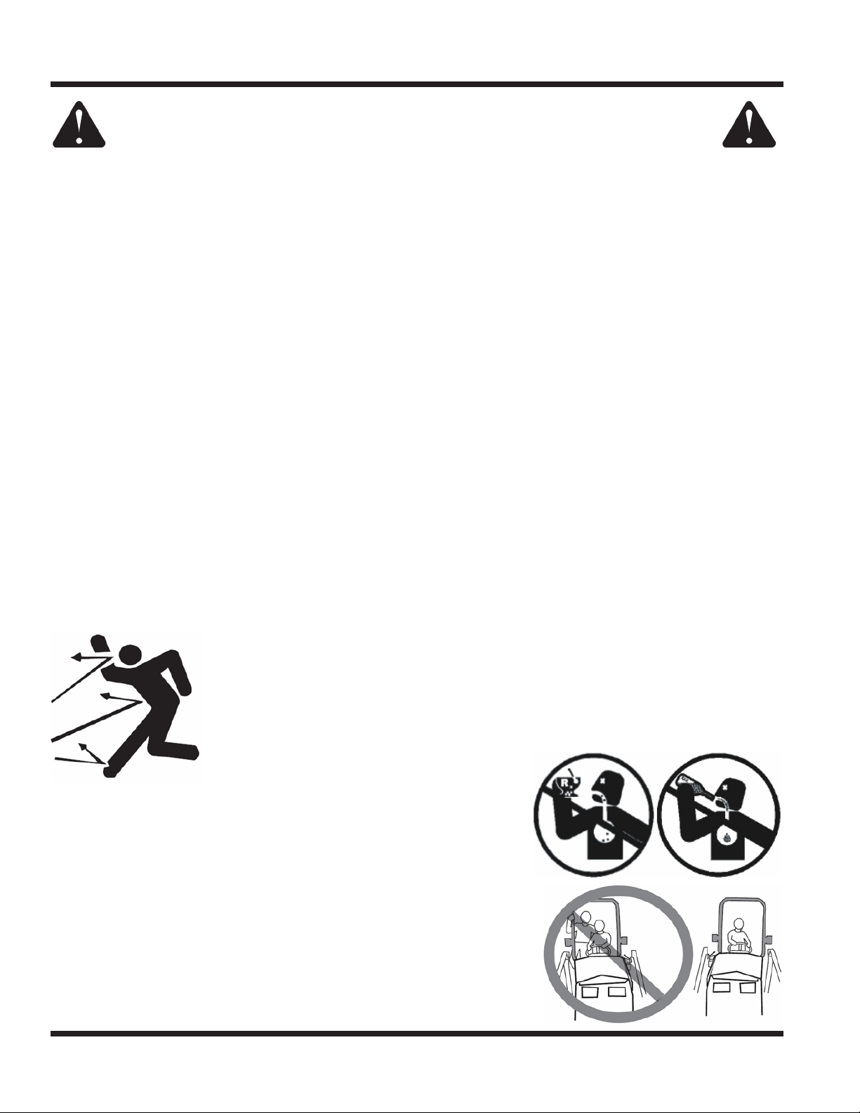
Preventing Accidents
• Clear working area of objects that might be hit or thrown from machine.
• Keep people and pets out of working area.
• Know the work area well before operation. Do not operate where traction or
stability is questionable.
• Reduce speed when you are operating over rough ground.
• Equipment can cause serious injury and/or death when improperly used.
Before operating, know and understand
the operation and safety of the power
unit and the attachment being used.
• Do not operate machine if you are not in good physical and
mental health, if you will be distracted by personal devices, or are
under the inuence of any substance which might impair decision, dexterity, or judgment.
• Children are attracted to machine activity. Be aware of children
and do not allow them in the working area. Turn o the machine if
a child enters the work area.
Keep Riders O
• Only allow the operator on the power unit. Keep riders o.
• Never allow riders on any attachment or accessory.
Safety - 14
SAFETY
General Safety Procedures
for Ventrac Power Units, Attachments, & Accessories
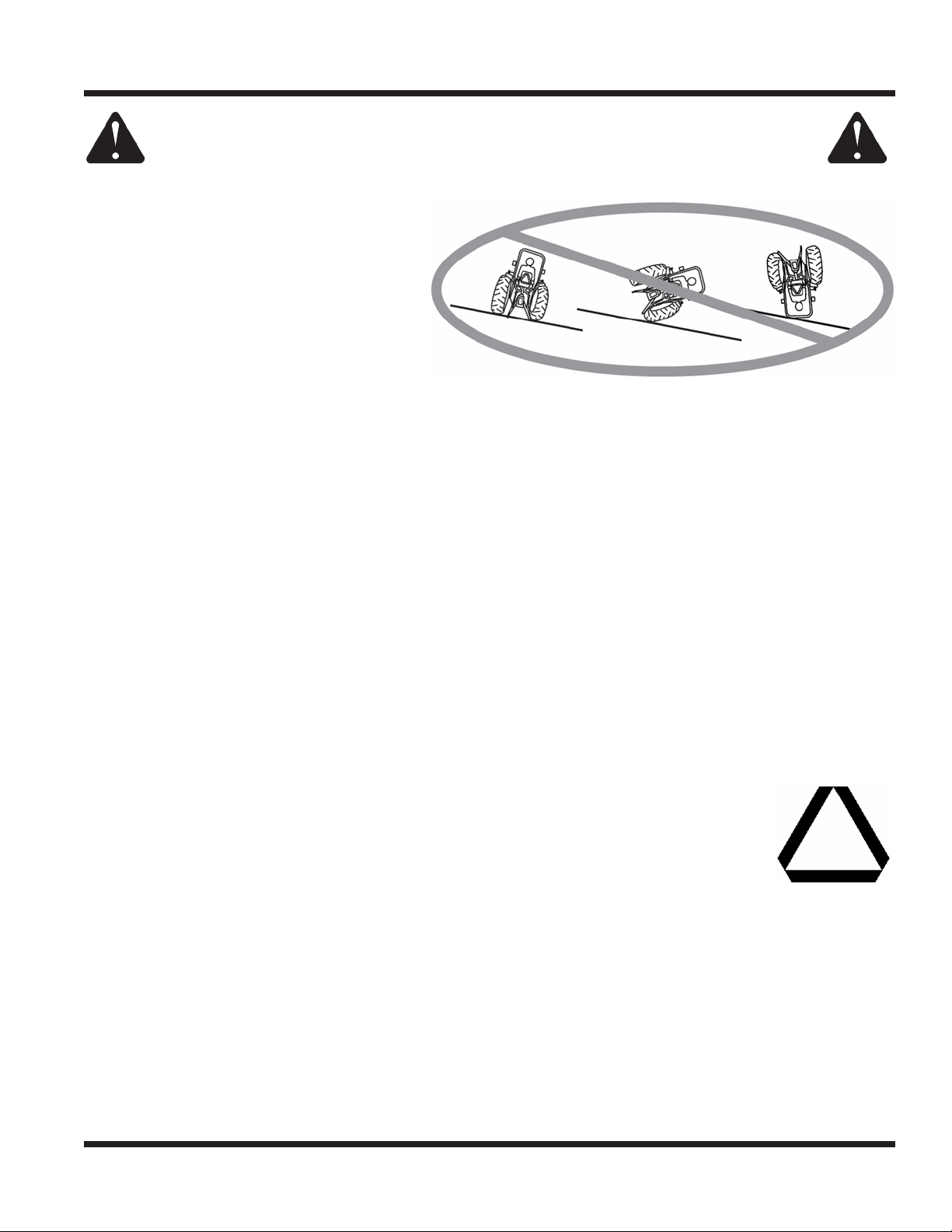
Operating On Slopes
• Slopes can cause loss-of-control and
tip-over accidents, which can result in
severe injury or death. Be familiar with the
emergency parking brake, along with the
power unit controls and their functions.
• If power unit is equipped with a fold down
roll bar, it must be locked in the upright
position when operating on any slope.
• Use low range (if equipped) when operating
on slopes greater than 15 degrees.
• Do not stop or start suddenly when operating on slopes.
• Never shift between high and low range while on a slope. Always move the power unit to level ground
and engage the parking brake before shifting range or placing the power unit in neutral.
• Variables such as wet surface and loose ground will reduce the degree of safety. Do not drive where
machine could lose traction or tip over.
• Keep alert for hidden hazards in the terrain.
• Stay away from drop-os, ditches, and embankments.
• Sharp turns should be avoided when operating on slopes.
• Pulling loads on hills decreases safety. It is the responsibility of the owner/operator to determine loads
that can safely be controlled on slopes.
• Transport machine with attachment lowered or close to the ground to improve stability.
• While operating on slopes, drive in an up and down direction when possible. If turning is necessary
while driving across slopes, reduce speed and turn slowly in the downhill direction.
• Assure a sucient supply of fuel for continuous operation. A minimum of one-half tank of fuel is recommended.
Roadway Safety
• Operate with safety lights when operating on or near roadways.
• Obey all state and local laws concerning operation on roadways.
• Slow down and be careful of trac when operating near or crossing roadways. Stop before crossing
roads or sidewalks. Use care when approaching areas or objects that may obscure vision.
• If there is doubt of safety conditions, discontinue machine operation until a time when
operation can be performed safely.
• When operating near or on roadways, have a Slow Moving Vehicle Emblem clearly
displayed.
Truck Or Trailer Transport
• Use care when loading or unloading machine into a truck or trailer.
• Use full width ramps for loading machine into a truck or trailer.
• The parking brake is not sucient to lock the machine during transport. Always secure the power unit
and/or attachment to the transporting vehicle securely using straps, chains, cable, or ropes. Both front
and rear straps should be directed down and outward from the machine.
• Shut o fuel supply to power unit during transport on truck or trailer.
• If equipped, turn the battery disconnect switch to the O position to shut o electrical power.
Safety - 15

SAFETY
General Safety Procedures
for Ventrac Power Units, Attachments, & Accessories
Maintenance
• Keep all safety decals legible. Remove all grease dirt, and debris from safety decals and instructional labels.
• If any decals are faded, illegible, or missing, contact your dealer promptly for replacements.
• When new components are installed, be sure that current safety decals are axed to the replacement
components.
• If any component requires replacement, use only original Ventrac replacement parts.
• Always turn the battery disconnect to the O position or disconnect the battery before performing any
repairs. Disconnect the negative terminal rst and the positive terminal last. Reconnect the positive
terminal rst and the negative terminal last.
• Keep all bolts, nuts, screws, and other fasteners properly tightened.
• Always lower the attachment to the ground, engage parking brake, shut o engine, and remove the
ignition key. Make sure all moving parts have come to a complete stop before cleaning, inspection,
adjusting or repairing.
• If the power unit, attachment, or accessory requires repairs or adjustments not instructed in the operator’s
manual, the power unit, attachment, or accessory must be taken to an authorized Ventrac dealer for service.
• Never perform maintenance on the power unit and/or attachment if someone is in the operator’s station.
• Always use protective glasses when handling the battery.
• Check all fuel lines for tightness and wear on a regular basis. Tighten or repair them as needed.
• To reduce the hazard of re, keep the battery compartment, engine, and muer areas free of grass,
leaves, and excessive grease.
• Do not touch the engine, the muer, or other exhaust components while the engine is running or immediately after stopping the engine. These areas may be hot enough to cause a burn.
• Allow the engine to cool before storing and do not store near an open ame.
• Do not change the engine governor settings or over-speed the engine. Operating engine at excessive
speed may increase the hazard of personal injury.
• Springs may contain stored energy. Use caution when disengaging or removing springs and/or spring
loaded components.
• An obstruction or blockage in a drive system or moving/rotating parts may cause a buildup of stored
energy. When the obstruction or blockage is removed, the drive system or moving/rotating parts may
move suddenly. Do not attempt to remove an obstruction or blockage with your hands. Keep hands,
feet, and clothing away from all power-driven parts.
• Dispose of all uids in accordance with local laws.
Fuel Safety
• To avoid personal injury or property damage, use extreme care in handling gasoline. Gaso-
line is extremely ammable and the vapors are explosive.
• Do not refuel machine while smoking or at a location near ames or sparks.
• Always refuel the machine outdoors.
• Do not store machine or fuel container indoors where fumes or fuel can reach an open
ame, spark, or pilot light.
• Only store fuel in an approved container. Keep out of reach of children.
• Never ll containers inside a vehicle or on a truck or trailer bed with a plastic liner. Always place containers
on the ground away from your vehicle before lling.
• Remove machine from the truck or trailer and refuel it on the ground. If this is not possible, refuel the
machine using a portable container, rather than from a fuel dispenser nozzle.
• Never remove fuel cap or add fuel with the engine running. Allow engine to cool before refueling.
• Never remove fuel cap while on a slope. Only remove when parked on a level surface.
• Replace all fuel tank and container caps securely.
Safety - 16
SAFETY
General Safety Procedures
for Ventrac Power Units, Attachments, & Accessories
Fuel Safety (continued)
• Do not overll fuel tank. Only ll to bottom of fuel neck, do not ll fuel neck full. Overlling of fuel tank could
result in engine ooding, fuel leakage from the tank, and/or damage to the emissions control system.
• If fuel is spilled, do not attempt to start the engine. Move the power unit away from the fuel spill and
avoid creating any source of ignition until fuel vapors have dissipated.
• If the fuel tank must be drained, it should be drained outdoors into an approved container.
• Dispose of all uids in accordance with local laws.
• Check all fuel lines for tightness and wear on a regular basis. Tighten or repair them as needed.
• The fuel system is equipped with a shut-o valve. Shut o the fuel when transporting the machine to
and from the job, when parking the machine indoors, or when servicing the fuel system.
Hydraulic Safety
• Make sure all hydraulic connections are tight and all hydraulic hoses and tubes are in good condition.
Repair any leaks and replace any damaged or deteriorated hoses or tubes before starting the machine.
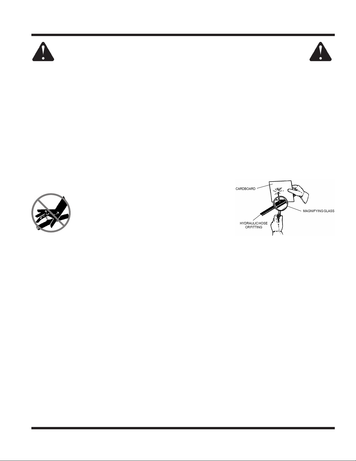
• Hydraulic leaks can occur under high pressure. Hydraulic leaks require special care and attention.
• Use a piece of cardboard and a magnifying glass to locate sus-
pected hydraulic leaks.
• Keep body and hands away from pinhole leaks
or nozzles that eject high pressure hydraulic uid.
Hydraulic uid escaping under high pressure can
penetrate the skin causing serious injury, leading to
severe complications and/or secondary infections
if left untreated. If hydraulic uid is injected into the
skin, seek immediate medical attention no matter
how minor the injury appears.
• Hydraulic system may contain stored energy. Before performing maintenance or repairs on the hydraulic
system, remove attachments, engage parking brake, disengage weight transfer system (if equipped),
shut o engine, and remove ignition key. To relieve pressure on the auxiliary hydraulic system, shut o the
power unit engine and move the hydraulic control lever left and right before disconnecting the auxiliary
hydraulic quick couplers.
• Dispose of all uids in accordance with local laws.
3400 Safety Procedures
• Power unit hydraulic system may contain stored energy. Before performing maintenance or repairs on
the auxiliary hydraulic circuit, remove attachments, engage the park brake, disengage weight transfer
system (if equipped), shut o engine, and remove the ignition key.
• Weight transfer spring may contain stored energy. Always disengage the weight transfer system (if
equipped) before performing maintenance or repairs on the weight transfer system, the front hitch, or
the lift hydraulics.
Operator Platform Access
• The operator platform is to be accessed from the left side of the power unit. Mounting and dismounting
the 3400 should only be done from this side.
Safety - 17
SAFETY
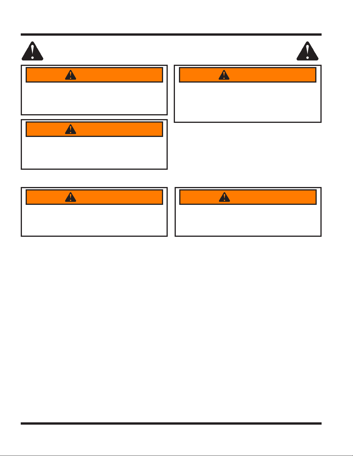
3400 Safety Procedures
WARNING
The engine exhaust and some of its constituents
contain chemicals known to the State of California
to cause cancer and birth defects or other
reproductive harm.
Oils, fuel, and uids from this power unit as well
as waste produced by component wear contain
or emit chemicals known to the State of California
to cause cancer and birth defects or other
reproductive harm.
WARNING
WARNING
Battery posts, terminals, and related accessories
contain lead and lead compounds which are
known to the State of California to cause cancer
and birth defects or other reproductive harm.
Roll Over Protective Structure (ROPS)
WARNING
Keep the ROPS locked in the upright position and
the seat belt securely fastened during operation.
Failure to do so could result in serious injury or
loss of life.
Your power unit is equipped with a Roll-Over Protective Structure (ROPS). This ROPS was tested in accordance with ISO 21299 (ROPS) and ISO 3776-2 and ISO 3776-3 (Seat Belt Anchorage). This ROPS is certi-
ed for use on a Ventrac 3400 with a maximum GVW of 2,200 pounds (1,000 Kg).
• ROPS certication applies only when the roll bar is locked in the upright position. Be aware there is no
rollover protection when a folding ROPS is in the down position.
• DO NOT remove the ROPS. Alterations to the ROPS structure are not permitted.
• Lower the roll bar only when absolutely necessary and raise the roll bar to the upright position as soon
as clearance allows. Never lower a folding ROPS in areas where there are slopes, drop os, or water.
• Check carefully for overhead clearances (i.e. branches, doorways, electrical wires) before driving under
any objects and do not contact them.
• Always wear the seat belt when the roll bar is locked in the upright position. Be certain the seat belt can
be released quickly in the event of an emergency.
• Do not wear a seat belt when the roll bar has been lowered to the down position.
• If any part of this ROPS experiences structural damage, the entire ROPS must be replaced.
• Inspect the seat belt for wear or damage before use. Failure to inspect or maintain the seat belt can
cause injury or loss of life.
Alterations or modications to this machine and/or
the ROPS structure can reduce safety and could
cause damage to the machine. Do not alter the
ROPS. Do not alter any other safety devices.
WARNING
Safety - 18
SAFETY
3400 Safety Procedures
Operator Safety Interlock System
The 3400 power unit is equipped with a safety interlock system. This system:
• Prevents the engine from starting unless the parking brake is engaged.
• Prevents the PTO from starting if the operator is not in the seat.
• Prevents the power unit from driving if the parking brake is engaged.
• Shuts o the PTO if the operator leaves the seat.
• Shuts o the engine (and fuel pump) if the operator leaves the seat without engaging the parking brake.
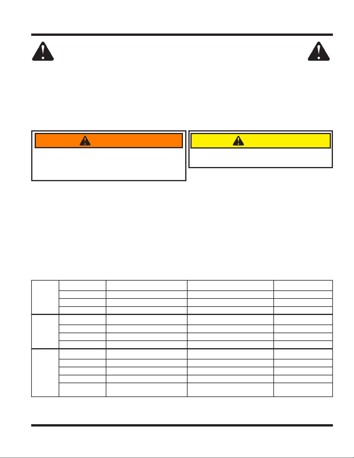
Testing the Safety Interlock System
WARNING
Never operate the power unit if the safety interlock
system is malfunctioning. Do not disengage or bypass
The daily inspection should be performed prior to
initial startup for the day.
CAUTION
any switch. Failure to heed warning could result in
injury to yourself and others, or damage to property.
Perform the following safety interlock tests daily. Before testing, park the power unit on a level surface,
place wheel chocks in front and back of wheels, and place the high/low range shift lever in the neutral
position. After testing is complete, place the high/low shift lever in either high or low range, set the parking
brake, and remove the wheel chocks.
Tests 1-3 test the ‘Engine Start’ function. For each test, turn the key to the RUN position (do not start the
engine). As listed for each test, engage or disengage the parking brake and sit on the seat or raise body
weight from seat. The engine starter should or should not engage as described for each test.
Tests 4-6 test the ‘Engine Run’ function. For each test, start the power unit so that the engine is running. As
listed for each test, engage or disengage the parking brake and sit on the seat or raise body weight from
seat. The engine should continue running or stop running as described for each test.
Tests 7-10 test the ‘PTO’ function. For each test, turn the key to the RUN position (do not start the engine).
As listed for each test, place the PTO switch in the ON or OFF position and sit on the seat or raise body
weight from seat. The electric PTO clutch will make an audible noise when it engages or disengages.
Test Number Parking Brake Engaged Operator Present in Seat Engine Starts
Engine
Start
Engine
Run
PTO
1 No Yes No
2 Yes No Yes
3 Yes Ye s Yes
Test Number Parking Brake Engaged Operator Present in Seat Engine Runs
4 Yes Ye s Yes
5 Yes No Yes
6 No No No
Test Number PTO Switch Operator Present in Seat PTO Clutch
7 O Ye s O
8 Pull to ‘On’ Position No No
9 Pull to ‘On’ Position Ye s Yes
10 On
Raise Operator Body Weight from
Seat
PTO Disengages
(1/2 second delay)
If the power unit fails any one of the safety interlock tests, refer to the troubleshooting section for using the
TCM (tractor control module) to diagnose electrical problems.
Safety - 19
OPERATIONAL CONTROLS
OPERATIONAL CONTROLS
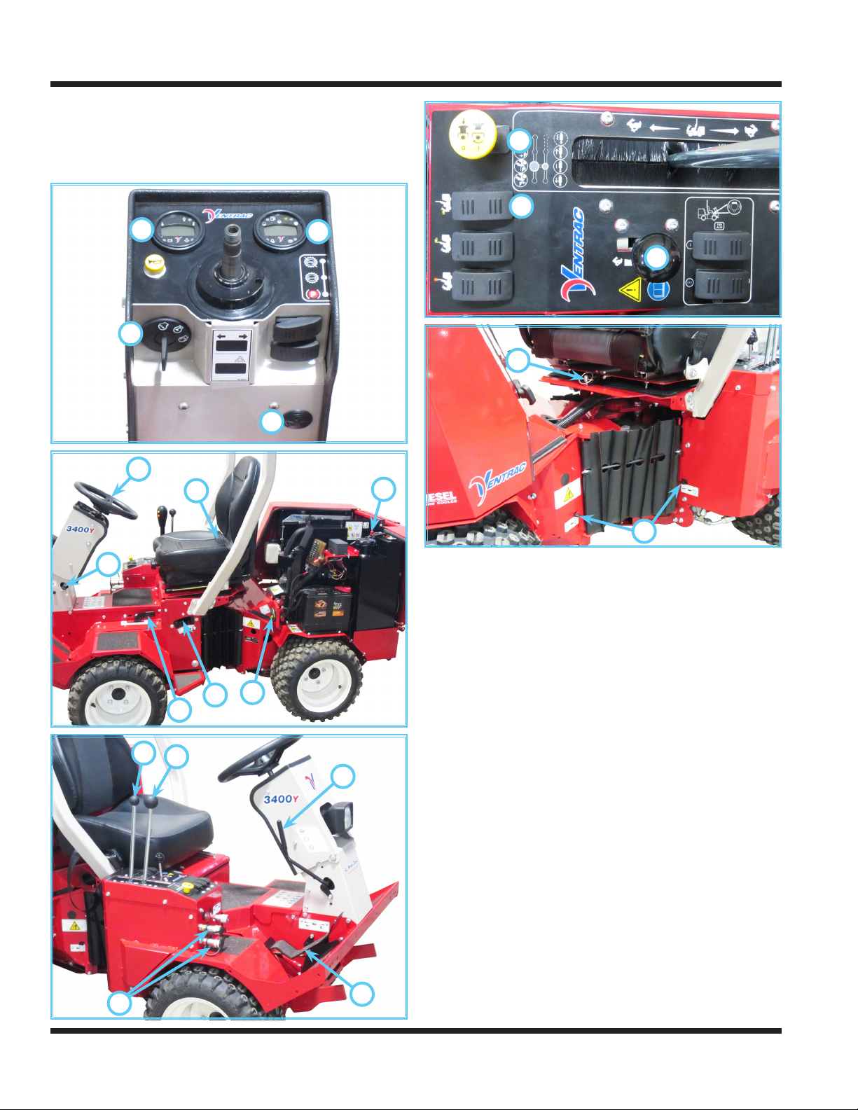
Standard Operational Control Locations
Use the following images to help identify the locations
of operational controls. The letter next to each control
can be referenced to the list that follows these images.
A
C
D
E
J
B
K
R
S
T
U
V
F
I
H
G
M
L
O
A. RPM/Hour Cluster Gauge
B. Fuel Cluster Gauge
C. Ignition Switch
D. Warning Alarm (Continuous)
E. Steering Wheel
F. Steering Tilt Adjustment Lever
G. Front Hitch Latch Lever
H. Weight Transfer Select Lever
I. Circuit Breaker & Battery Disconnect
J. Seat Belt
K. Fuel Shut-o Valve
L. Primary SDLA Control Lever
M. Secondary SDLA Control Lever
N. Foot Pedal
O. Selector Lever/Parking Brake
P. Auxiliary Hydraulic Quick Couplers
R. PTO Switch
S. Headlight Switch
T. Throttle Lever
U. Seat Latch Strap
V. Transaxle Neutral Levers
P
N
Operation - 20
OPERATIONAL CONTROLS
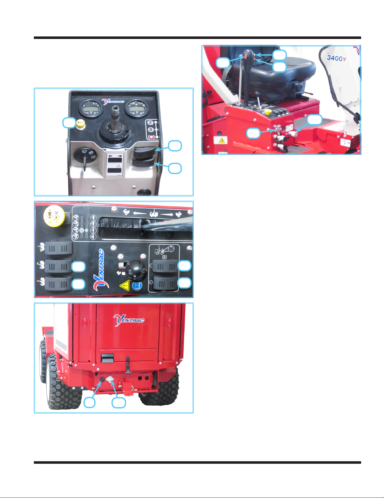
Optional Operational Control Locations
Use the following images to help identify the locations
of operational controls for optional kits. The letter
next to each control can be referenced to the list that
follows these images.
JJ
KK
KK
AA
DD
EE
BB
CC
FF
GG
MM
LL
AA. Horn Switch
BB. Directional Signal Switch
CC. Hazard Flasher Switch
DD. Work Light Switch
EE. Strobe Light Switch
FF. Rear 12V Switch (On/O)
GG. Rear 12V Switch (Momentary On/O/On)
HH. Rear 12V 4-Pin Socket
II. Back Up Alarm
JJ. Front 12V Switch (On/O)
KK. Front 12V Buttons (Momentary On)
LL. Front 12V 4-Pin Socket
MM. Front Hitch Valve
II
HH
Operation - 21
OPERATIONAL CONTROLS
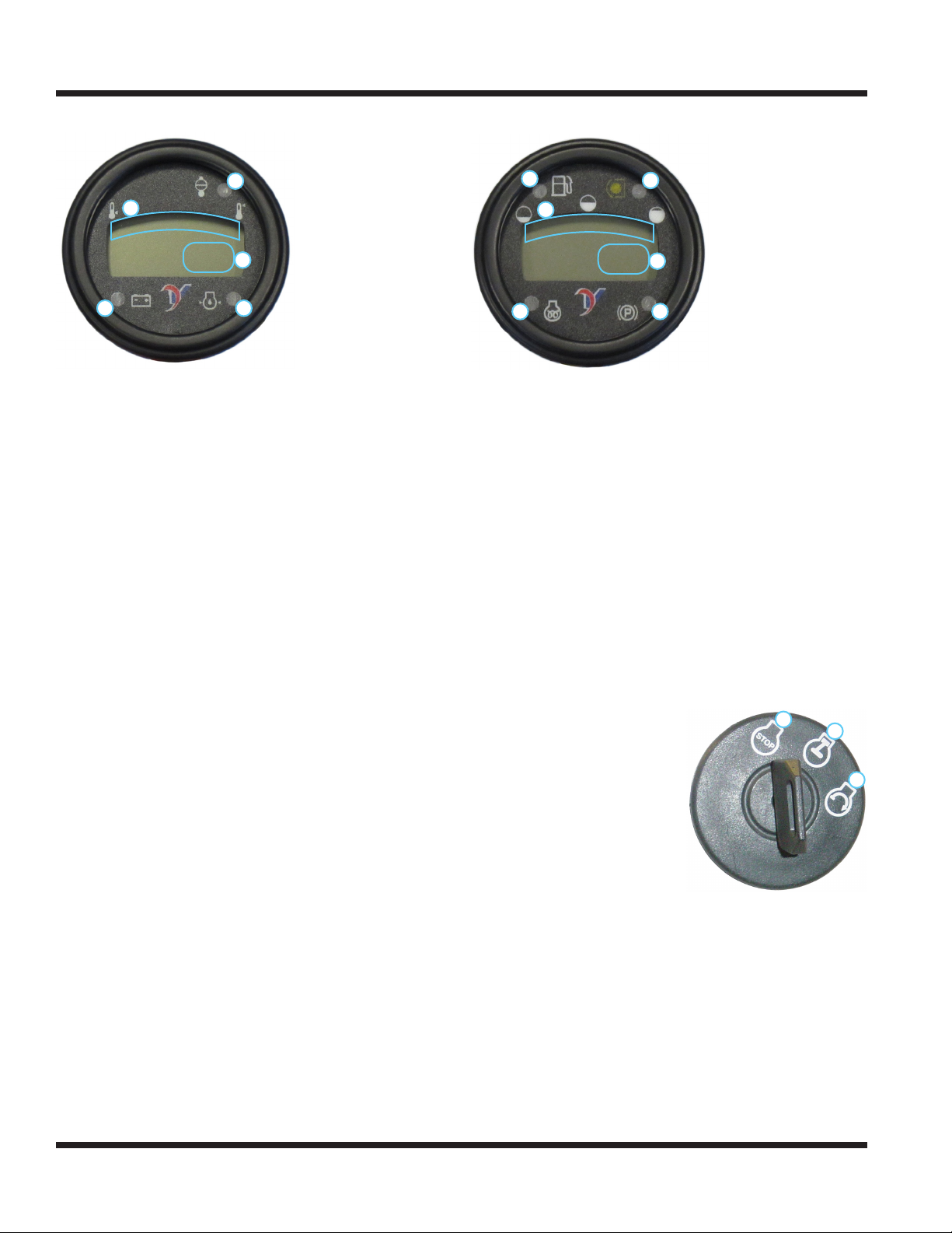
RPM/Hour Cluster Gauge (A)
1. Water Temperature
2
1
3
4 5
The water temperature gauge displays the temperature of the engine cooling system.
The water high temperature warning light and
audible alarm activate when the temperature of the
engine cooling system reaches unsafe levels. If this
light and alarm comes on during operation, park the
power unit, turn the PTO o, reduce engine speed
to low idle, and allow the engine to cool. Check the
radiator screen and clean, if necessary. If engine
temperature continues to rise, shut o the engine. If
the engine continually overheats, refer to the troubleshooting section for possible problems.
The tachometer / hour meter displays both the
engine run time and the engine speed. When
the engine is not running and the ignition switch
is turned to the On position, the gauge displays
the accumulated time the ignition key has been
switched to the On position. When the engine is running, the gauge displays the engine speed in RPM.
The low voltage warning light and audible alarm
activate when the voltage drops to unacceptable
levels. If this light and alarm comes on, shut o
any unnecessary lights and accessories to reduce
current draw. If voltage continues to drop, park the
power unit, shut o the engine, and turn the ignition
key to the o position. Refer to the troubleshooting
section for possible problems.
The low engine oil pressure warning light and
audible alarm activate when the engine oil pressure
is below safe levels. The light comes on when the
ignition key is switched to the on position and stays
illuminated until the engine is started and safe oil
pressure develops. If this light and alarm comes on
during operation, immediately shut o the engine.
Do not restart the engine until the problem has been
located and corrected.
Gauge
2. Water High Temperature
Warning Light
3. Tachometer / Hour Meter
4. Low Voltage Warning
Light
5. Low Engine Oil Pressure
Warning Light
Fuel Cluster Gauge (B)
1. Fuel Gauge
2
1
5
3
4
6
2. Low Fuel Warning Light
3. PTO Indicator Light
4. Speedometer
5. Glow Plug Indicator
Light
6. Park Brake Indicator
Light
The fuel gauge displays the level of fuel in the tank.
The low fuel warning light activates when the fuel
level is low.
The PTO indicator light activates when the power
unit’s PTO clutch is engaged.
The speedometer displays the speed of the power
unit. The speedometer can be set to display either
miles per hour (mph) or kilometers per hour (kph).
The glow plug indicator light indicates activation
of the glow plugs for preheating the engine. The
glow plugs activate when the key is turned to the
on position. When the glow plug light turns o, the
engine is ready to start.
The park brake indicator light activates when the
park brake is set.
Ignition Switch (C)
1.
O or Stop Position -
all 12 volt power going
through the key switch is
o.
2. On or Run Position engine run position, 12
volt power is sent to
accessories.
3. Start Position - when the
key is turned to the start
position, the starter will engage.
1
2
Warning Alarm (D)
The warning alarm works with the RPM/Hour
cluster gauge to alert the operator to problems.
The warning alarm sounds a continuous signal
whenever a warning is displayed on the RPM/
Hour cluster gauge. If the warning alarm sounds,
immediately check the RPM/Hour cluster gauge to
determine the cause of the warning and then take
appropriate action.
3
Operation - 22
OPERATIONAL CONTROLS
Steering Wheel (E)
Turn the steering wheel to the left (counterclockwise)
to turn the power unit to the left. Turn the wheel to the
right (clockwise) to turn the power unit to the right.
Steering Tilt Adjustment Lever (F)
Push down on the steering tilt adjustment lever to
release the adjustment lock. Tilt the steering column forward or backward to the desired position.
Release the steering tilt adjustment lever to lock the
steering column in place.
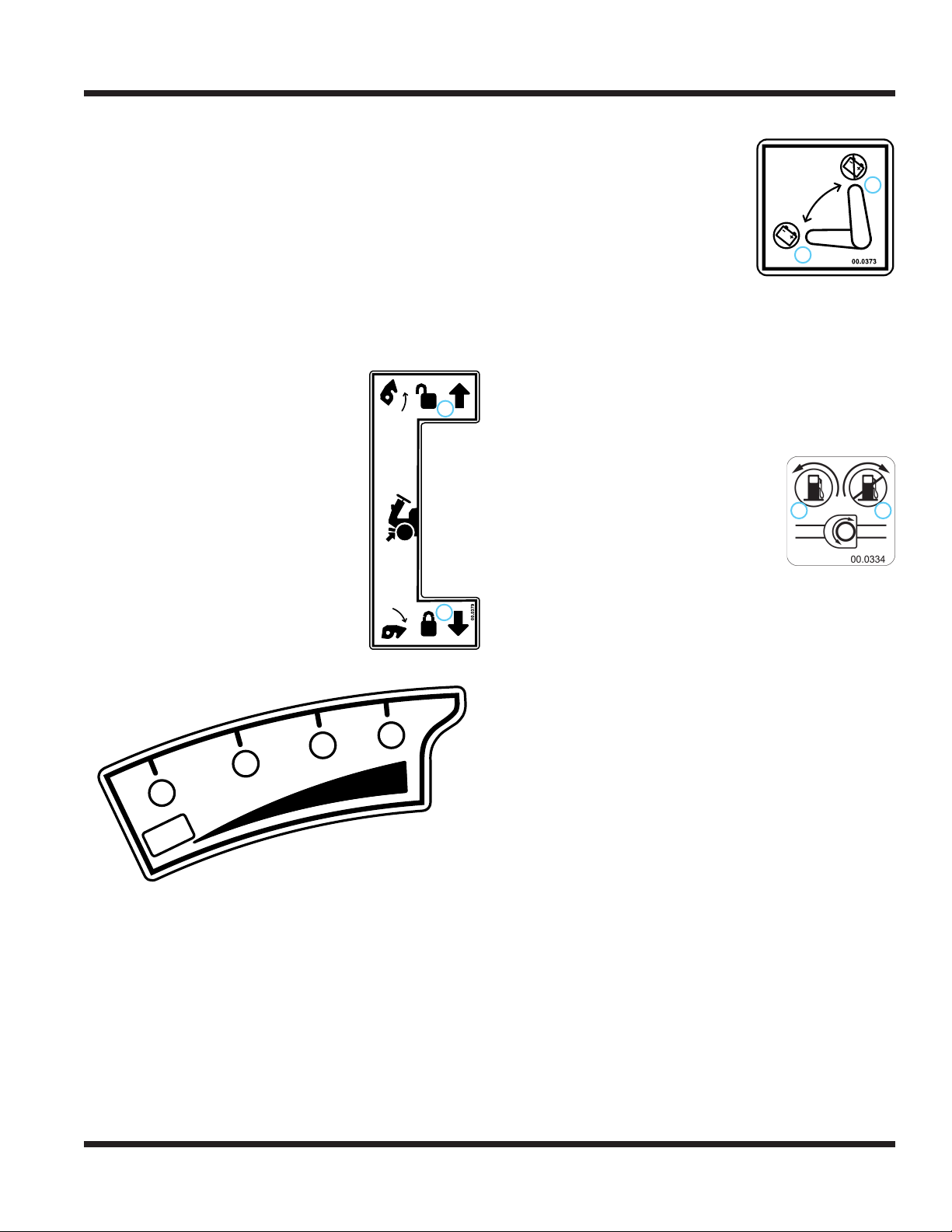
Front Hitch Latch Lever (G)
The front hitch latch lever
locks or unlocks the hitch
latch.
Rotate the front hitch latch lever
toward the front of the power unit to
unlock the hitch latch when attaching or detaching Ventrac attachments.
Rotate the front hitch latch lever
toward the rear of the power unit to
lock the hitch latch over the hitch
arm pins on Ventrac attachments.
Ensure the lever is secured in the
frame notch and the front hitch lever
lock is in place.
1. Unlocked
2. Locked
1
2
Weight Transfer Select Lever (H)
Circuit Breaker & Battery Disconnect (I)
The circuit breaker/battery
disconnect switch controls power
to the entire electrical system.
Turning the switch to position 0
disables the electrical system,
allowing electrical components
to be serviced.
Seat Belt (J)
Sit down on the seat and adjust
the seat to the desired position. Pull the seat belt
across your lap, ensure the seat belt is not twisted,
and insert the belt latch plate into the seat belt
buckle until it clicks. Pull up on the latch plate to
make sure it is secure. Pull on the loose end of the
seat belt to snug the seat belt across your lap.
0
1
0. Electrical Power O
1. Electrical Power On
Fuel Shut-o Valve (K)
The fuel shut-o valve controls the ow
of fuel to the power unit engine. Turning
the valve counterclockwise (1) to the
stop allows fuel to ow to the engine.
Turning the valve clockwise (0) to the
stop shuts o the fuel ow to prevent
fuel leakage when changing fuel lters
or servicing the fuel system. Turn o the fuel shut-o
valve when transporting the power unit on a truck or
trailer and when parking the power unit indoors.
1 0
0. Fuel O
1. Fuel On
3
00.0359
2
1
0
TC
The weight transfer system transfers weight from
the attachment to the front wheels of the power
unit. Transferring weight from the attachment to the
power unit increases the traction control, improves
hillside maneuverability, aids in lifting the attachment,
reduces steering eort, and lessens the attachment
resistance when in contact with the ground.
The operator can select dierent transfer rates by
selecting one of the four positions from no weight
transfer (0) to maximum weight transfer (3). Set the
weight transfer to 0 when attaching or detaching any
attachment.
Operation - 23
 Loading...