


Operator’s Manual
3400Y
Serial Number 3400Y-AK01001 --
Original Operator’s Manual
VENTRAC.COM
Revised 12/06/18
09.10087 Rev. 10
View all manuals
Visit ventrac.com/manuals
500 Venture Drive
Orrville Oh 44667
www.ventrac.com
for the latest version of this
operator’s manual.
A downloadable parts manual
is also available.
To the Owner
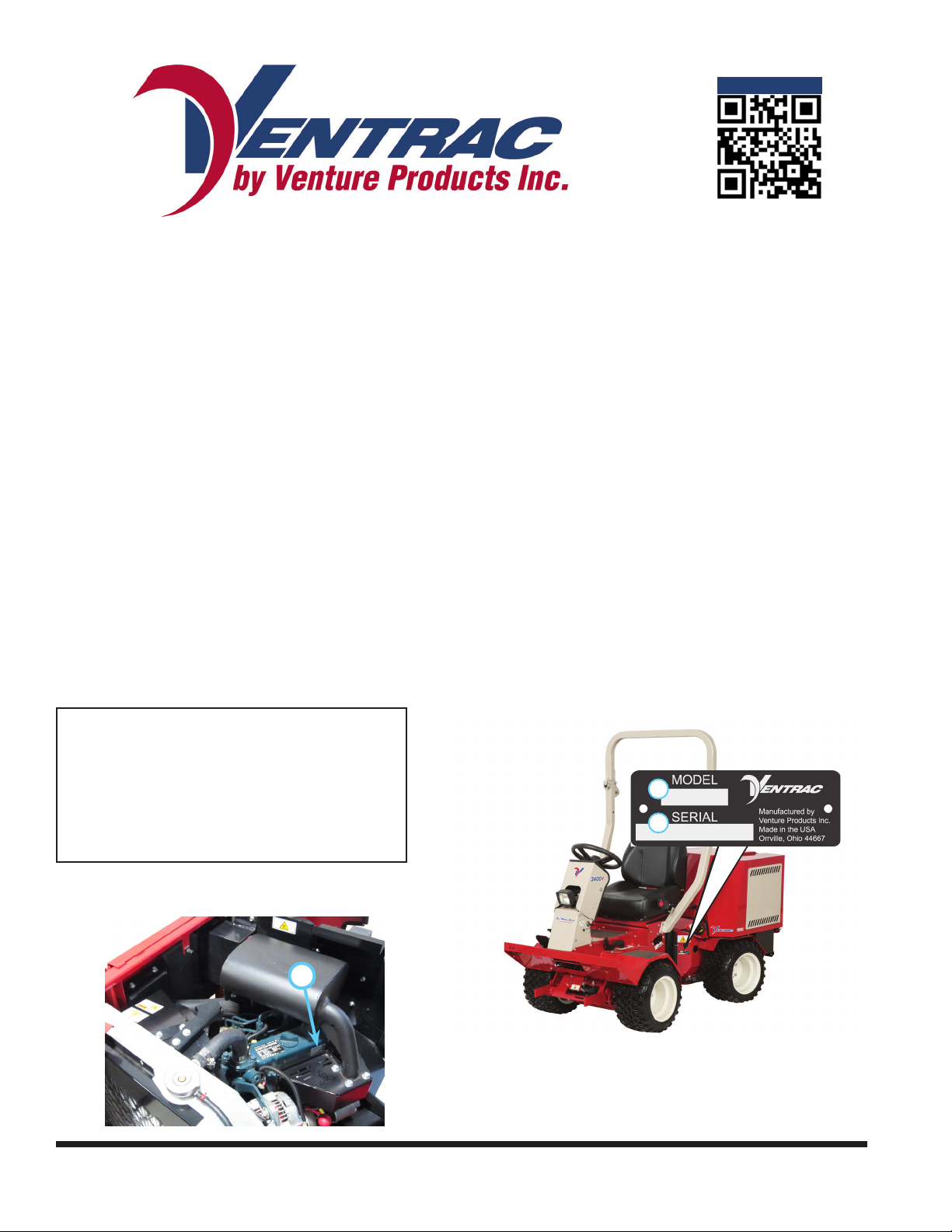
Contact Information and Product Identication
If you need to contact an authorized Ventrac dealer for information on servicing your product,
always provide the product model and serial numbers.
Please ll in the following information for future reference. See the picture(s) below to nd the
location of the identication numbers. Record them in the spaces provided.
Date of Purchase: __________________________________________________________________
Dealer: ___________________________________________________________________________
Dealer Address: ____________________________________________________________________
____________________________________________________________________
Dealer Phone Number: ______________________________________________________________
Dealer Fax Number: ________________________________________________________________
Model # (A): ___________________________
Serial # (B): ____________________________
A
B
Afx Part/Serial Number label here.
Engine Serial # (C) _________________________
C
Venture Products Inc. reserves the right to make changes
in design or specications without obligation to make like
changes on previously manufactured products.
2

TABLE OF CONTENTS
INTRODUCTION PAGE 7
Product Description ................................................................................................................................ 8
Why Do I Need an Operator’s Manual? ................................................................................................. 8
Using Your Manual ................................................................................................................................. 9
Manual Glossary ....................................................................................................................................9
SAFETY PAGE 10
Safety Decals ....................................................................................................................................... 10
General Safety Procedures .................................................................................................................. 13
Training Required .................................................................................................................................13
Personal Protective Equipment Requirements ....................................................................................13
Operation Safety ..................................................................................................................................13
Preventing Accidents ............................................................................................................................14
Keep Riders O .................................................................................................................................... 14
Operating On Slopes ............................................................................................................................15
Roadway Safety ................................................................................................................................... 15
Truck Or Trailer Transport ....................................................................................................................15
Maintenance ......................................................................................................................................... 16
Fuel Safety ........................................................................................................................................... 16
Hydraulic Safety ................................................................................................................................... 17
3400 Safety Procedures .......................................................................................................................17
Operator Platform Access .................................................................................................................... 17
Roll Over Protective Structure (ROPS) ................................................................................................ 18
3400 Safety Procedures .......................................................................................................................18
Operator Safety Interlock System ........................................................................................................19
OPERATIONAL CONTROLS PAGE 20
Standard Operational Control Locations .............................................................................................. 20
Optional Operational Control Locations ...............................................................................................21
RPM/Hour Cluster Gauge (A) ..............................................................................................................22
Fuel Cluster Gauge (B) ........................................................................................................................22
Ignition Switch (C) ................................................................................................................................ 22
Warning Alarm (D) ................................................................................................................................ 22
Steering Wheel (E) ............................................................................................................................... 23
Steering Tilt Adjustment Lever (F) ........................................................................................................23
Front Hitch Latch Lever (G) ..................................................................................................................23
Weight Transfer Select Lever (H) ......................................................................................................... 23
Circuit Breaker & Battery Disconnect (I) ..............................................................................................23
Seat Belt (J) .........................................................................................................................................23
Fuel Shut-o Valve (K) .........................................................................................................................23
SDLA Control Levers (L & M) ...............................................................................................................24
Foot Pedal (N) ...................................................................................................................................... 24
Selector Lever/Parking Brake(O) .........................................................................................................24
Auxiliary Hydraulic Quick Couplers (P) ................................................................................................25
Power Take O (PTO) Switch (R) ........................................................................................................25
Headlight Switch (S) .............................................................................................................................25
3

TABLE OF CONTENTS
OPERATIONAL CONTROLS (Continued)
Throttle Lever (T) .................................................................................................................................25
Seat Latch Strap (U) ............................................................................................................................25
Transmission Neutral Levers (V) ..........................................................................................................25
Horn Switch (AA) .................................................................................................................................. 25
Directional Signal Switch (BB) .............................................................................................................25
Hazard Flasher Switch (CC) ................................................................................................................26
Work Light Switch (DD) ........................................................................................................................26
Strobe Light Switch (EE) ...................................................................................................................... 26
12 Volt Rear Switches & 4-Pin Socket (FF, GG, & HH) ........................................................................26
12 Volt Front Switches & 4-Pin Socket (RR, SS, & TT) .......................................................................26
Front Hitch Valve (MM) ........................................................................................................................26
GENERAL OPERATION PAGE 27
Daily Inspection .................................................................................................................................... 27
Starting The Engine .............................................................................................................................27
Forward And Reverse .......................................................................................................................... 28
Stopping The Power Unit .....................................................................................................................28
Shutting O The Engine .......................................................................................................................28
Attaching ..............................................................................................................................................28
Detaching ............................................................................................................................................. 29
Operating Attachments .........................................................................................................................29
Front Hitch ............................................................................................................................................ 29
PTO Drive Belt & Pulley .......................................................................................................................29
Front Auxiliary Couplers ....................................................................................................................... 29
Weight Transfer .................................................................................................................................... 30
Roll-Over Protection System (ROPS) ..................................................................................................30
12 Volt 4-Pin Auxiliary Outlets (Optional Accessory) ............................................................................ 30
Operating On Slopes ............................................................................................................................31
Operation in Water, Mud, Snow, or Ice ................................................................................................31
Towing Or Pushing The Power Unit .....................................................................................................31
SERVICE PAGE 32
Service And General Maintenance .......................................................................................................32
Cleaning And Appearance Care ........................................................................................................... 32
Service Access Points .......................................................................................................................... 33
Checking Hydraulic Oil Level ...............................................................................................................34
Changing Hydraulic Oil Filter ...............................................................................................................35
Changing Hydraulic Oil ........................................................................................................................35
Changing Rear Transaxle Dierential Oil ............................................................................................. 36
Checking Engine RPM ......................................................................................................................... 36
Checking Engine Oil Level ................................................................................................................... 37
Changing Engine Oil And Filter ............................................................................................................ 37
Inspecting & Resetting The Air Filter Restriction Gauge ...................................................................... 38
Changing Air Filter Elements ................................................................................................................39
Filling The Fuel Tank ............................................................................................................................39
4

TABLE OF CONTENTS
SERVICE (Continued)
Servicing The Fuel Filter/Water Separator ........................................................................................... 40
Changing The Fuel Filter ......................................................................................................................40
Priming The Fuel System .....................................................................................................................40
Checking The Fan (Alternator) Belt ......................................................................................................40
Adjusting Fan (Alternator) Belt Tension ................................................................................................41
Cleaning Engine Compartment & Engine ............................................................................................41
Servicing The Cooling System .............................................................................................................41
Checking The Cooling System .............................................................................................................42
Cleaning The Radiator And Screen ...................................................................................................... 42
Draining The Cooling System ..............................................................................................................43
Servicing The Battery ........................................................................................................................... 44
Removing The Battery .........................................................................................................................44
Installing The Battery ...........................................................................................................................44
Cleaning The Battery And Terminals .................................................................................................... 45
Charging The Battery ........................................................................................................................... 45
Jump Starting Procedure .....................................................................................................................45
TCM (Tractor Control Module) Explanation .........................................................................................46
Replacing Fuses (Power Relay Module) .............................................................................................. 46
Replacing Fuses (Front Fuse Panel) ...................................................................................................46
Replacing Fuses (Rear Fuse Panel) .................................................................................................... 47
Replacing Fuses (Engine) .................................................................................................................... 47
Switching Speedometer (MPH or Km/H) ..............................................................................................48
Replacing Light Bulbs (Headlights) ...................................................................................................... 48
Replacing The Taillights ....................................................................................................................... 48
Replacing the Work Lights ...................................................................................................................48
Replacing The Turn Signal Lights ........................................................................................................48
Replacing The Strobe Light Bulb .........................................................................................................48
Drive Belt Inspection ............................................................................................................................49
Engine Drive Belt Inspection & Adjustment .......................................................................................... 49
Engine Drive Belt Replacement ...........................................................................................................50
PTO Belt Replacement ........................................................................................................................50
Transaxle Drive Belt Replacement .......................................................................................................51
Clutch Air Gap Inspection & Adjustment .............................................................................................. 52
Wheel Removal & Installation ..............................................................................................................52
Tire Pressure ........................................................................................................................................52
ROPS And Seat Belt Inspection ........................................................................................................... 53
Parking Brake Inspection & Adjustment ............................................................................................... 53
Neutral Adjustment ............................................................................................................................... 54
Storage ................................................................................................................................................. 54
Maintenance Schedule .........................................................................................................................56
Maintenance Checklist ......................................................................................................................... 57
Ventrac Maintenance Log ....................................................................................................................58
5

TABLE OF CONTENTS
TROUBLESHOOTING PAGE 61
Wiring Diagram Reference Key ............................................................................................................61
Wiring Diagram - Rear Harness ........................................................................................................... 62
Wiring Diagram - Front Harness ..........................................................................................................63
Wiring Diagram Engine Harness .......................................................................................................... 64
Wiring Diagram - Optional 30.0219 4-Pin Female Socket & 30.0218 4-Pin Male Plug........................65
Electrical Troubleshooting Using The Tractor Control Module (TCM) ..................................................66
Electrical Troubleshooting Guide .........................................................................................................68
Engine .................................................................................................................................................. 69
Electrical ............................................................................................................................................... 70
Hydraulic ..............................................................................................................................................71
Power Unit ............................................................................................................................................ 71
SPECIFICATIONS PAGE 72
Engine .................................................................................................................................................. 72
Electrical ............................................................................................................................................... 72
Power Train ..........................................................................................................................................72
Controls & Instrument Panel ................................................................................................................72
Other Features ..................................................................................................................................... 72
Dimensions ..........................................................................................................................................73
Fluid Capacities & Specications ......................................................................................................... 73
Amperage Draw Chart .........................................................................................................................74
Belt Chart .............................................................................................................................................74
WARRANTY PAGE 75
6
INTRODUCTIONINTRODUCTION
enture Products Inc. is pleased to provide you with your new
V
Ventrac power unit! We hope that Ventrac equipment will
provide you with a ONE Tractor Solution.
Listed below are just some of the items that can provide you
versatility as you use your 3400. Please visit our web site, or
contact your authorized Ventrac dealer for a complete list of
items available for your new power unit.
Item Description
12 Volt Front Kit 70.3036
12 Volt Rear Kit 70.3050
Backup Alarm Kit 70.3037
Directional / Hazard Signal Kit 70.3046
ES220 Spreader 39.55500
Front Hitch Valve Kit 70.3042
Horn Kit 70.3041
Accessories
Rear Weight Bracket Kit 70.3043
Item Description
Aerator with Open Spoon Tine 39.55490
Aerator with Slitter/Slicer Tine 39.55492
Aerator with Coring Tine 39.55494
Blade - 48” 39.55251
Blade - 60” 39.55252
Blower 39.35445
Broom 39.35402
Edger 39.55332
Attachments
Field Mower - 45” 39.35102
Finish Mower - 52” 39.35100
Finish Mower - 60” 39.35101
Part Number
Part Number
Item Description
Strobe Light Kit 70.3045
Suspension Seat 70.3040
Trailer Mover Hitch 70.2016
Weather Cab 70.2015
Work Light Kit 70.3044
Dual Hydraulic Auxiliary Kit 70.3039
Accessories
Item Description
Rear Discharge Mower - 52” 39.35107
Power Bucket - 30” 39.55213
Power Bucket - 48” 39.55214
Snow Blower 39.35427
Stump Grinder 39.35300
Terra Rake - 52” 39.55431
V-Blade 39.55271
Attachments
Part Number
Part Number
Introduction - 7

INTRODUCTION
Product Description
The Ventrac 3400 is a unique All Wheel Drive power unit that distributes its power to four equal size otation tires to provide excellent control, traction, stability, maneuverability, and braking. Its innovative, patented Tandem Drive Train is coupled with an articulating and oscillating, uni-body frame to create a power
unit with quiet, ecient, and powerful performance. The 3400 is equipped with power steering and has a
turning radius of 28 inches (71 cm), allowing it to maneuver in and around tight places with ease.
The 3400 is designed with the operator seated at the front of the power unit for unobstructed visibility of
attachments and terrain ahead. This design uses a rear mounted engine that keeps heat, exhaust, and
noise behind the operator.
Ventrac’s patented SDLA control, located next to the operator, allows for easy control of Speed, Direction,
Lift, and Auxiliary functions with one hand.
The Ventrac attachment mount system allows the operator to change front mounted attachments quickly
and eciently.
Standard features of the 3400 power unit include:
• a fold down roll bar.
• a wire harness that is pre-wired for optional accessories.
• a complete electrical system circuit breaker and battery disconnect.
• a computer controlled onboard diagnostic system for the electrical circuits.
• two cluster gauges on the steering column. One gauge includes a fuel gauge, speedometer, glow
plug indicator, parking brake indicator, PTO ‘On’ indicator, and a low fuel indicator. The second gauge
includes an engine temperature gauge, hour meter / tachometer, and warning lights for high engine
coolant temperature, low engine oil pressure, and low battery voltage. All of the warning indicator lights
also trigger an audible alarm to insure the operator is aware of an unsafe condition.
Why Do I Need an Operator’s Manual?
This manual has been created to help you gain the important knowledge of what is needed to safely
operate, maintain, and service your machine. It is divided into sections for convenient reference of the
appropriate section.
You must read and understand the operator’s manual for each piece of Ventrac equipment you own. Reading the operator’s manual will help you become familiar with each specic piece of equipment. Understanding the operator’s manual will help you, as well as others, avoid personal injury and/or damage to the
equipment. Keep this manual with the machine at all times. The manual should remain with the machine
even if it is sold. If this manual becomes damaged or unreadable, it should be replaced immediately. Contact your local Ventrac dealer for a replacement.
When using a Ventrac attachment, be sure to read and follow the safety and operating instructions of both
the power unit and the attachment being used to ensure the safest operation possible.
The information in this manual provides the operator with the safest procedures to operate the machine
while getting the maximum use out of the unit. Failure to follow the safety precautions listed in this manual
may result in personal injury and/or damage to the equipment.
Introduction - 8
INTRODUCTION
Using Your Manual
Throughout this manual, you will encounter special messages and symbols that identify potential safety
concerns to help you as well as others avoid personal injury or damage to the equipment.
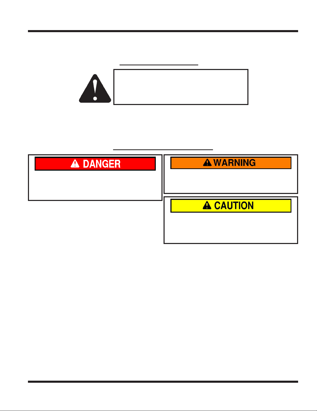
SYMBOL DEFINITIONS
ATTENTION
This symbol identies potential health and
safety hazards. It marks safety precautions.
Your safety and the safety of others is involved.
There are three signal words that describe the level of safety concern: Danger, Warning, and Caution.
Safety should always be the #1 priority when working on or operating equipment. Accidents are more likely
to occur when proper operating procedures are not followed or inexperienced operators are involved.
Note: Right-Hand and Left-Hand orientations may be referred to at dierent places throughout this manual.
Right-Hand and Left-Hand is determined as if sitting on the power unit seat facing forward.
SIGNAL WORD DEFINITIONS
Indicates an imminently hazardous situation
which, if not avoided, will result in death or
serious injury. This signal word is limited to the
most extreme cases.
Indicates a potentially hazardous situation
which, if not avoided, could result in death or
serious injury.
Indicates a potentially hazardous situation
which, if not avoided, may result in minor or
moderate injury and/or property damage. It may
also be used to alert against unsafe practices.
Manual Glossary
Power Unit A Ventrac tractor or other Ventrac engine powered device that may be operated by itself or
with an attachment or accessory.
Attachment A piece of Ventrac equipment that requires a Power Unit for operation.
Accessory A device that attaches to a Power Unit or Attachment to extend its capabilities.
Machine Describes any “Attachment” or “Accessory” that is used in conjunction with a power unit.
Introduction - 9
SAFETY
SAFETY
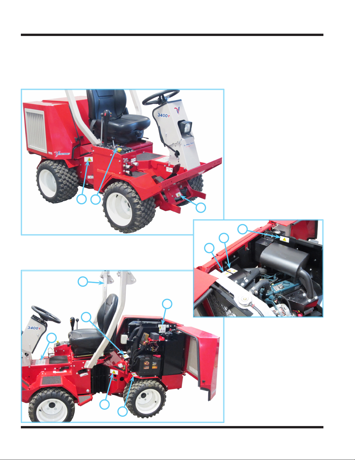
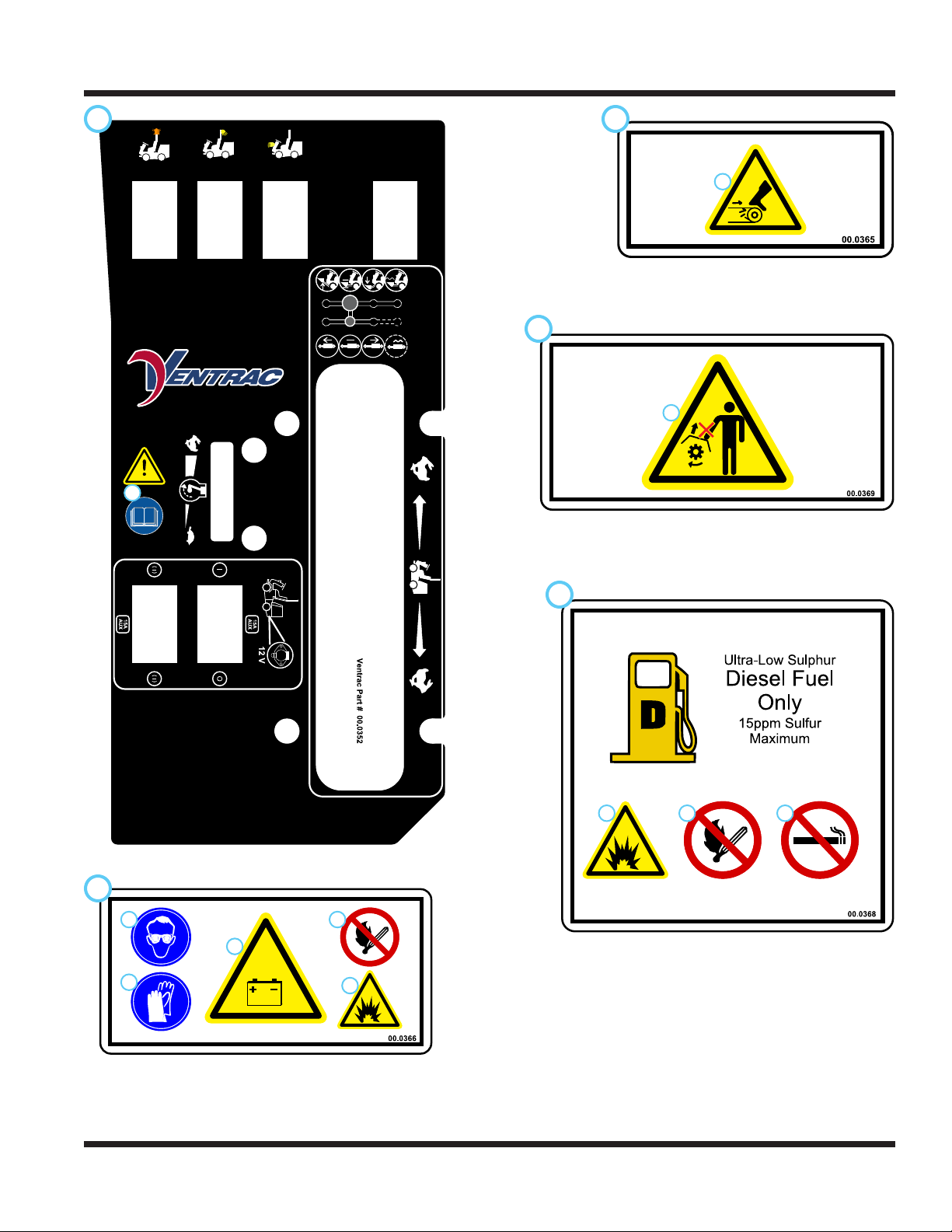
Safety Decals
The following safety decals must be maintained on your Ventrac 3400 power unit.
Keep all safety decals legible. Remove all grease, dirt, and debris from safety decals and instructional
labels. If any decals are faded, illegible, or missing, contact your dealer promptly for replacements.
When new components are installed, be sure that current safety decals are axed to the replacement
components.
G
C
A
B
H
J
H
F
D
C
C
E
Safety - 10
SAFETY
A B
C
1
1. Cutting / dismemberment / entanglement hazard -
Do not remove shields.
Stay away from moving parts.
1
1. Cutting / entanglement hazard Stay away from moving parts.
1
1. WARNING: Read operator’s manual.
E
2
1
3
D
1 2 3
4
1. DANGER: Explosion / re hazard.
2. Keep away from re, sparks, and pilot lights when
5
refueling or storing machine and fuel.
3. Smoking is prohibited.
1. DANGER: Battery acid is caustic and can cause chemical burns. Keep bystanders a safe distance from the battery.
2. Wear eye protection, such as goggles or a face shield, when checking or servicing batteries.
3. Wear appropriate protective gear, such as rubber gloves and an apron, when checking or servicing batteries.
4. Do not expose batteries to arcs, sparks, or open ames. Do not use smoking materials near batteries.
5. Explosion hazard - batteries produce ammable and explosive gases.
Safety - 11
SAFETY
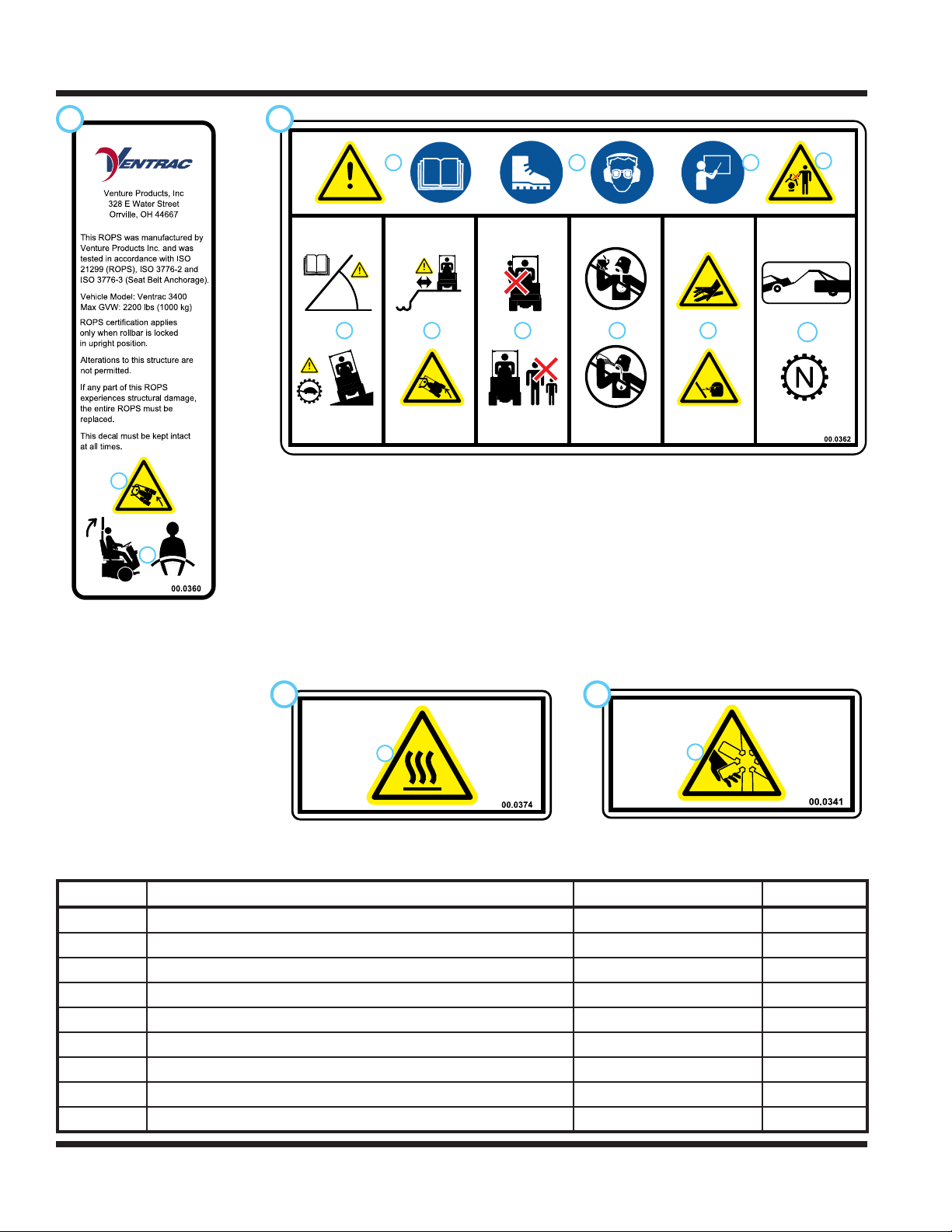
F
1
2
1. WARNING: Rollover!
2. Keep the roll bar in the raised
and locked position and keep
the seat belt securely fastened
during operation.
G
1 2 3
5 6 7 8 9
1. WARNING: Read operator’s manual.
2. Wear personal protective gear, such as safety glasses, closed toe shoes or boots, and ear protection.
3. Operators must receive training prior to operating the machine.
4. Do not operate with shields or guards removed.
5. WARNING: Read slope operation instructions. Slow down when operating on slopes. Keep the roll bar
in the raised and locked position and the seat belt securely fastened.
6. WARNING: Keep a safe distance from the edge of drop-os, ditches, and embankments. The machine
could roll over if a wheel drops over the edge or if the edge caves in.
7. Do not carry passengers. Stop the machine if someone enters the area.
8. Do not operate while under the inuence of drugs or alcohol.
9. WARNING: Hydraulic uid is under high pressure and can penetrate skin, causing injury. Keep hands,
face, and body away from pinholes or nozzles the eject hydraulic uid under high pressure.
10. When towing or pushing the power unit, the transaxles must be disengaged by moving the front and
rear axle neutral links to the neutral position or damage to the transaxles will result.
4
10
H
1
1. Hot surface hazard - Hot surfaces can cause sever
burns. Allow engine, exhaust components, and surrounding surfaces to cool before servicing.
J
1
1. Cutting / dismemberment / entanglement
hazard - Stay away from moving parts.
Decal Description Part Number Quantity
A Dash Side 00.0352 1
B Warning, Moving Parts 00.0365 1
C Warning, Do Not Remove Shields 00.0369 3
D Warning, Diesel Only 00.0368 1
E Warning, Battery 00.0366 1
F ROPS Certication 00.0360 1
G Warning, Operator Safety 00.0362 1
H Warning, Hot Surface 00.0374 2
J Warning, Fan 00.0341 1
Safety - 12
SAFETY
General Safety Procedures
for Ventrac Power Units, Attachments, & Accessories
Training Required
• The owner of this machine is solely responsible for properly training the operators.
• The owner/operator is solely responsible for the operation of this
machine and prevention of accidents or injuries occurring to him/herself, other people, or property.
• Do not allow operation or service by children or untrained personnel.
Local regulations may restrict the age of the operator.
• Before operating this machine, read the operator’s manual and understand its contents.
• If the operator of the machine cannot understand this manual, then it
is the responsibility of this machine’s owner to fully explain the material
within this manual to the operator.
• Learn and understand the use of all controls.
• Know how to stop the power unit and all attachments quickly in the event of an emergency.
Personal Protective Equipment Requirements
It is the responsibility of the owner to be sure that the operators use the proper personal protective equipment while operating the machine. Required personal protective equipment includes, but is not limited to,
the following list.
• Wear a certied ear protection device to prevent loss of hearing.
• Prevent eye injury by wearing safety glasses while operating the machine.
• Closed toe shoes must be worn at all times.
• Long pants must be worn at all times.
• When operating in dusty conditions, it is recommended that a dust mask be worn.
Operation Safety
• Inspect machine before operation. Repair or replace any damaged, worn, or missing parts. Be sure
guards and shields are in proper working condition and are secured in place. Make all necessary
adjustments before operating machine.
• Some pictures in this manual may show shields or covers opened or removed in order to clearly illustrate
any instructions. Under no circumstance should the machine be operated without these devices in place.
• Alterations or modications to this machine can reduce safety and could cause damage to the machine.
Do not alter safety devices or operate with shields or covers removed.
• Before each use, verify that all controls function properly and inspect all safety devices. Do not operate
if controls or safety devices are not in proper working condition.
• Check parking brake function before operating. Repair or adjust parking brake if necessary.
• Observe and follow all safety decals.
• All controls are to be operated from the operator’s station only.
• Always wear a seat belt if the machine has a roll cage/bar installed and in upright position.
• Ensure the attachment or accessory is locked or fastened securely to the power unit before operating.
• Ensure that all bystanders are clear of the power unit and attachment before operating. Stop machine if
someone enters your work area.
• Always be alert to what is happening around you, but do not lose focus on the task you are performing.
Always look in the direction the machine is moving.
• Look behind and down before backing up to be sure of a clear path.
• If you hit an object, stop and inspect the machine. Make all necessary repairs before operating machine again.
• Stop operation immediately at any sign of equipment failure. An unusual noise can be a warning of equipment
failure or a sign that maintenance is required. Make all necessary repairs before operating machine again.
Safety - 13
SAFETY
General Safety Procedures
for Ventrac Power Units, Attachments, & Accessories
Operation Safety (continued)
• If equipped with a high/low range feature, never shift between high and low range while on a slope.
Always move the machine to level ground and engage the parking brake before shifting range.
• Do not leave machine unattended while it is running.
• Always park the machine on level ground.
• Always shut o engine when connecting attachment drive belt to the power unit.
• Never leave the operator’s station without lowering the attachment to the ground, setting the parking
brake, shutting o the engine, and removing the ignition key. Make sure all moving parts have come to
a complete stop before dismounting.
• Never leave equipment unattended without lowering the attachment to the ground, setting the parking
brake, shutting o the engine, and removing the ignition key.
• Only operate in well-lit conditions.
• Do not operate when there is a risk of lightning.
• Never direct the discharge of any attachment in the direction of people, buildings, animals, vehicles, or
other objects of value.
• Never discharge material against a wall or obstruction. Material may ricochet back towards the operator.
• Use extra caution when approaching blind corners, shrubs, trees, or other objects that may obscure vision.
• Do not run the engine in a building without adequate ventilation.
• Do not touch the engine or the muer while the engine is running or immediately after stopping the engine.
These areas may be hot enough to cause a burn.
• Do not change the engine governor settings or over-speed the engine. Operating engine at excessive speed
may increase the hazard of personal injury.
• To reduce the hazard of re, keep the battery compartment, engine, and muer areas free of grass, leaves,
excessive grease, and other ammable materials.
Preventing Accidents
• Clear working area of objects that might be hit or thrown from machine.
• Keep people and pets out of working area.
• Know the work area well before operation. Do not operate where traction or
stability is questionable.
• Reduce speed when you are operating over rough ground.
• Equipment can cause serious injury and/or death when improperly used.
Before operating, know and understand
the operation and safety of the power
unit and the attachment being used.
• Do not operate machine if you are not in good physical and
mental health, if you will be distracted by personal devices, or are
under the inuence of any substance which might impair decision, dexterity, or judgment.
• Children are attracted to machine activity. Be aware of children
and do not allow them in the working area. Turn o the machine if
a child enters the work area.
Keep Riders O
• Only allow the operator on the power unit. Keep riders o.
• Never allow riders on any attachment or accessory.
Safety - 14
SAFETY
General Safety Procedures
for Ventrac Power Units, Attachments, & Accessories
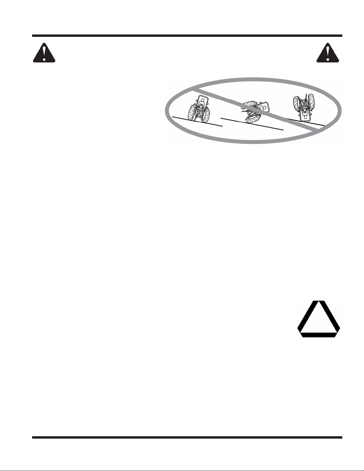
Operating On Slopes
• Slopes can cause loss-of-control and
tip-over accidents, which can result in
severe injury or death. Be familiar with the
emergency parking brake, along with the
power unit controls and their functions.
• If power unit is equipped with a fold down
roll bar, it must be locked in the upright
position when operating on any slope.
• Use low range (if equipped) when operating
on slopes greater than 15 degrees.
• Do not stop or start suddenly when operating on slopes.
• Never shift between high and low range while on a slope. Always move the power unit to level ground
and engage the parking brake before shifting range or placing the power unit in neutral.
• Variables such as wet surface and loose ground will reduce the degree of safety. Do not drive where
machine could lose traction or tip over.
• Keep alert for hidden hazards in the terrain.
• Stay away from drop-os, ditches, and embankments.
• Sharp turns should be avoided when operating on slopes.
• Pulling loads on hills decreases safety. It is the responsibility of the owner/operator to determine loads
that can safely be controlled on slopes.
• Transport machine with attachment lowered or close to the ground to improve stability.
• While operating on slopes, drive in an up and down direction when possible. If turning is necessary
while driving across slopes, reduce speed and turn slowly in the downhill direction.
• Assure a sucient supply of fuel for continuous operation. A minimum of one-half tank of fuel is recommended.
Roadway Safety
• Operate with safety lights when operating on or near roadways.
• Obey all state and local laws concerning operation on roadways.
• Slow down and be careful of trac when operating near or crossing roadways. Stop before crossing
roads or sidewalks. Use care when approaching areas or objects that may obscure vision.
• If there is doubt of safety conditions, discontinue machine operation until a time when
operation can be performed safely.
• When operating near or on roadways, have a Slow Moving Vehicle Emblem clearly
displayed.
Truck Or Trailer Transport
• Use care when loading or unloading machine into a truck or trailer.
• Use full width ramps for loading machine into a truck or trailer.
• The parking brake is not sucient to lock the machine during transport. Always secure the power unit
and/or attachment to the transporting vehicle securely using straps, chains, cable, or ropes. Both front
and rear straps should be directed down and outward from the machine.
• Shut o fuel supply to power unit during transport on truck or trailer.
• If equipped, turn the battery disconnect switch to the O position to shut o electrical power.
Safety - 15

SAFETY
General Safety Procedures
for Ventrac Power Units, Attachments, & Accessories
Maintenance
• Keep all safety decals legible. Remove all grease dirt, and debris from safety decals and instructional labels.
• If any decals are faded, illegible, or missing, contact your dealer promptly for replacements.
• When new components are installed, be sure that current safety decals are axed to the replacement
components.
• If any component requires replacement, use only original Ventrac replacement parts.
• Always turn the battery disconnect to the O position or disconnect the battery before performing any
repairs. Disconnect the negative terminal rst and the positive terminal last. Reconnect the positive
terminal rst and the negative terminal last.
• Keep all bolts, nuts, screws, and other fasteners properly tightened.
• Always lower the attachment to the ground, engage parking brake, shut o engine, and remove the
ignition key. Make sure all moving parts have come to a complete stop before cleaning, inspection,
adjusting or repairing.
• If the power unit, attachment, or accessory requires repairs or adjustments not instructed in the operator’s
manual, the power unit, attachment, or accessory must be taken to an authorized Ventrac dealer for service.
• Never perform maintenance on the power unit and/or attachment if someone is in the operator’s station.
• Always use protective glasses when handling the battery.
• Check all fuel lines for tightness and wear on a regular basis. Tighten or repair them as needed.
• To reduce the hazard of re, keep the battery compartment, engine, and muer areas free of grass,
leaves, and excessive grease.
• Do not touch the engine, the muer, or other exhaust components while the engine is running or immediately after stopping the engine. These areas may be hot enough to cause a burn.
• Allow the engine to cool before storing and do not store near an open ame.
• Do not change the engine governor settings or over-speed the engine. Operating engine at excessive
speed may increase the hazard of personal injury.
• Springs may contain stored energy. Use caution when disengaging or removing springs and/or spring
loaded components.
• An obstruction or blockage in a drive system or moving/rotating parts may cause a buildup of stored
energy. When the obstruction or blockage is removed, the drive system or moving/rotating parts may
move suddenly. Do not attempt to remove an obstruction or blockage with your hands. Keep hands,
feet, and clothing away from all power-driven parts.
• Dispose of all uids in accordance with local laws.
Fuel Safety
• To avoid personal injury or property damage, use extreme care in handling gasoline. Gaso-
line is extremely ammable and the vapors are explosive.
• Do not refuel machine while smoking or at a location near ames or sparks.
• Always refuel the machine outdoors.
• Do not store machine or fuel container indoors where fumes or fuel can reach an open
ame, spark, or pilot light.
• Only store fuel in an approved container. Keep out of reach of children.
• Never ll containers inside a vehicle or on a truck or trailer bed with a plastic liner. Always place containers
on the ground away from your vehicle before lling.
• Remove machine from the truck or trailer and refuel it on the ground. If this is not possible, refuel the
machine using a portable container, rather than from a fuel dispenser nozzle.
• Never remove fuel cap or add fuel with the engine running. Allow engine to cool before refueling.
• Never remove fuel cap while on a slope. Only remove when parked on a level surface.
• Replace all fuel tank and container caps securely.
Safety - 16
SAFETY
General Safety Procedures
for Ventrac Power Units, Attachments, & Accessories
Fuel Safety (continued)
• Do not overll fuel tank. Only ll to bottom of fuel neck, do not ll fuel neck full. Overlling of fuel tank could
result in engine ooding, fuel leakage from the tank, and/or damage to the emissions control system.
• If fuel is spilled, do not attempt to start the engine. Move the power unit away from the fuel spill and
avoid creating any source of ignition until fuel vapors have dissipated.
• If the fuel tank must be drained, it should be drained outdoors into an approved container.
• Dispose of all uids in accordance with local laws.
• Check all fuel lines for tightness and wear on a regular basis. Tighten or repair them as needed.
• The fuel system is equipped with a shut-o valve. Shut o the fuel when transporting the machine to
and from the job, when parking the machine indoors, or when servicing the fuel system.
Hydraulic Safety
• Make sure all hydraulic connections are tight and all hydraulic hoses and tubes are in good condition.
Repair any leaks and replace any damaged or deteriorated hoses or tubes before starting the machine.
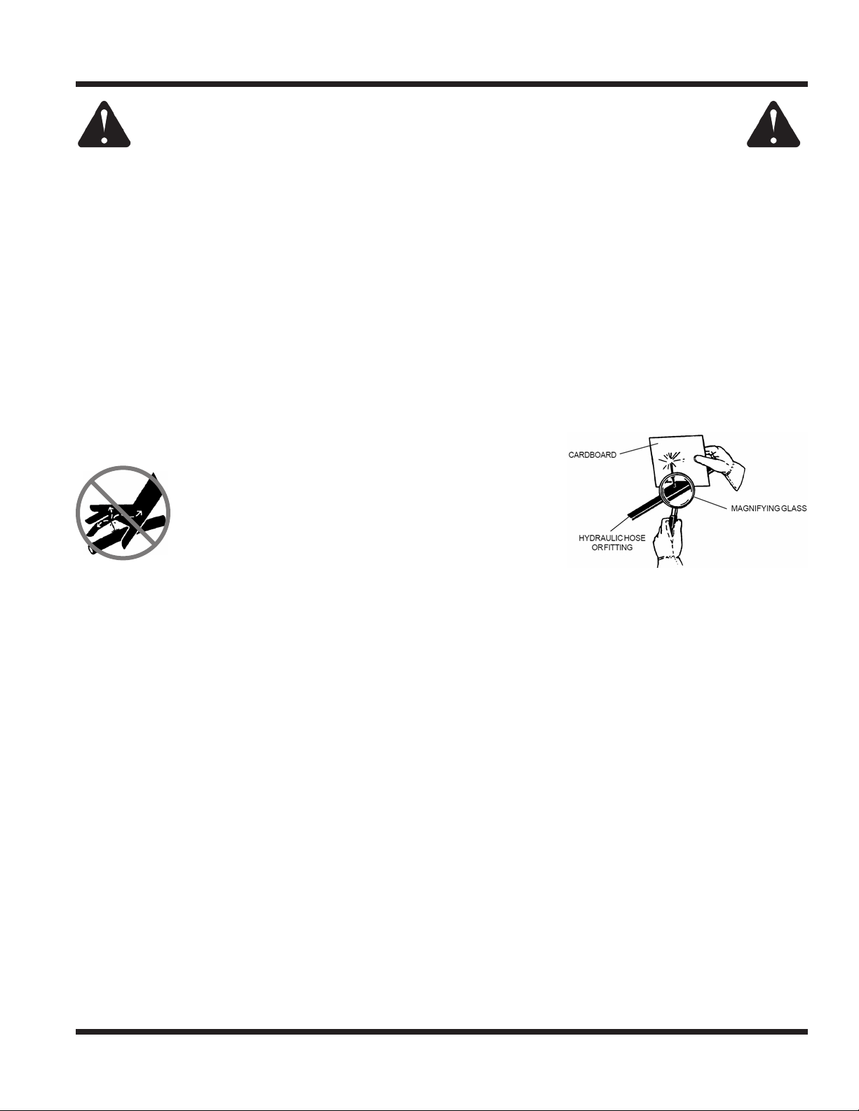
• Hydraulic leaks can occur under high pressure. Hydraulic leaks require special care and attention.
• Use a piece of cardboard and a magnifying glass to locate sus-
pected hydraulic leaks.
• Keep body and hands away from pinhole leaks
or nozzles that eject high pressure hydraulic uid.
Hydraulic uid escaping under high pressure can
penetrate the skin causing serious injury, leading to
severe complications and/or secondary infections
if left untreated. If hydraulic uid is injected into the
skin, seek immediate medical attention no matter
how minor the injury appears.
• Hydraulic system may contain stored energy. Before performing maintenance or repairs on the hydraulic
system, remove attachments, engage parking brake, disengage weight transfer system (if equipped),
shut o engine, and remove ignition key. To relieve pressure on the auxiliary hydraulic system, shut o the
power unit engine and move the hydraulic control lever left and right before disconnecting the auxiliary
hydraulic quick couplers.
• Dispose of all uids in accordance with local laws.
3400 Safety Procedures
• Power unit hydraulic system may contain stored energy. Before performing maintenance or repairs on
the auxiliary hydraulic circuit, remove attachments, engage the park brake, disengage weight transfer
system (if equipped), shut o engine, and remove the ignition key.
• Weight transfer spring may contain stored energy. Always disengage the weight transfer system (if
equipped) before performing maintenance or repairs on the weight transfer system, the front hitch, or
the lift hydraulics.
Operator Platform Access
• The operator platform is to be accessed from the left side of the power unit. Mounting and dismounting
the 3400 should only be done from this side.
Safety - 17
SAFETY
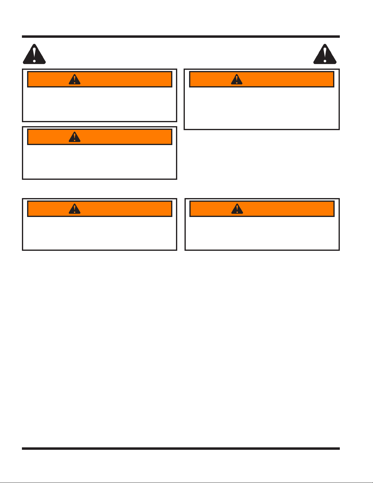
3400 Safety Procedures
WARNING
The engine exhaust and some of its constituents
contain chemicals known to the State of California
to cause cancer and birth defects or other
reproductive harm.
Oils, fuel, and uids from this power unit as well
as waste produced by component wear contain
or emit chemicals known to the State of California
to cause cancer and birth defects or other
reproductive harm.
WARNING
WARNING
Battery posts, terminals, and related accessories
contain lead and lead compounds which are
known to the State of California to cause cancer
and birth defects or other reproductive harm.
Roll Over Protective Structure (ROPS)
WARNING
Keep the ROPS locked in the upright position and
the seat belt securely fastened during operation.
Failure to do so could result in serious injury or
loss of life.
Your power unit is equipped with a Roll-Over Protective Structure (ROPS). This ROPS was tested in accordance with ISO 21299 (ROPS) and ISO 3776-2 and ISO 3776-3 (Seat Belt Anchorage). This ROPS is certi-
ed for use on a Ventrac 3400 with a maximum GVW of 2,200 pounds (1,000 Kg).
• ROPS certication applies only when the roll bar is locked in the upright position. Be aware there is no
rollover protection when a folding ROPS is in the down position.
• DO NOT remove the ROPS. Alterations to the ROPS structure are not permitted.
• Lower the roll bar only when absolutely necessary and raise the roll bar to the upright position as soon
as clearance allows. Never lower a folding ROPS in areas where there are slopes, drop os, or water.
• Check carefully for overhead clearances (i.e. branches, doorways, electrical wires) before driving under
any objects and do not contact them.
• Always wear the seat belt when the roll bar is locked in the upright position. Be certain the seat belt can
be released quickly in the event of an emergency.
• Do not wear a seat belt when the roll bar has been lowered to the down position.
• If any part of this ROPS experiences structural damage, the entire ROPS must be replaced.
• Inspect the seat belt for wear or damage before use. Failure to inspect or maintain the seat belt can
cause injury or loss of life.
Alterations or modications to this machine and/or
the ROPS structure can reduce safety and could
cause damage to the machine. Do not alter the
ROPS. Do not alter any other safety devices.
WARNING
Safety - 18
SAFETY
3400 Safety Procedures
Operator Safety Interlock System
The 3400 power unit is equipped with a safety interlock system. This system:
• Prevents the engine from starting unless the parking brake is engaged.
• Prevents the PTO from starting if the operator is not in the seat.
• Prevents the power unit from driving if the parking brake is engaged.
• Shuts o the PTO if the operator leaves the seat.
• Shuts o the engine (and fuel pump) if the operator leaves the seat without engaging the parking brake.
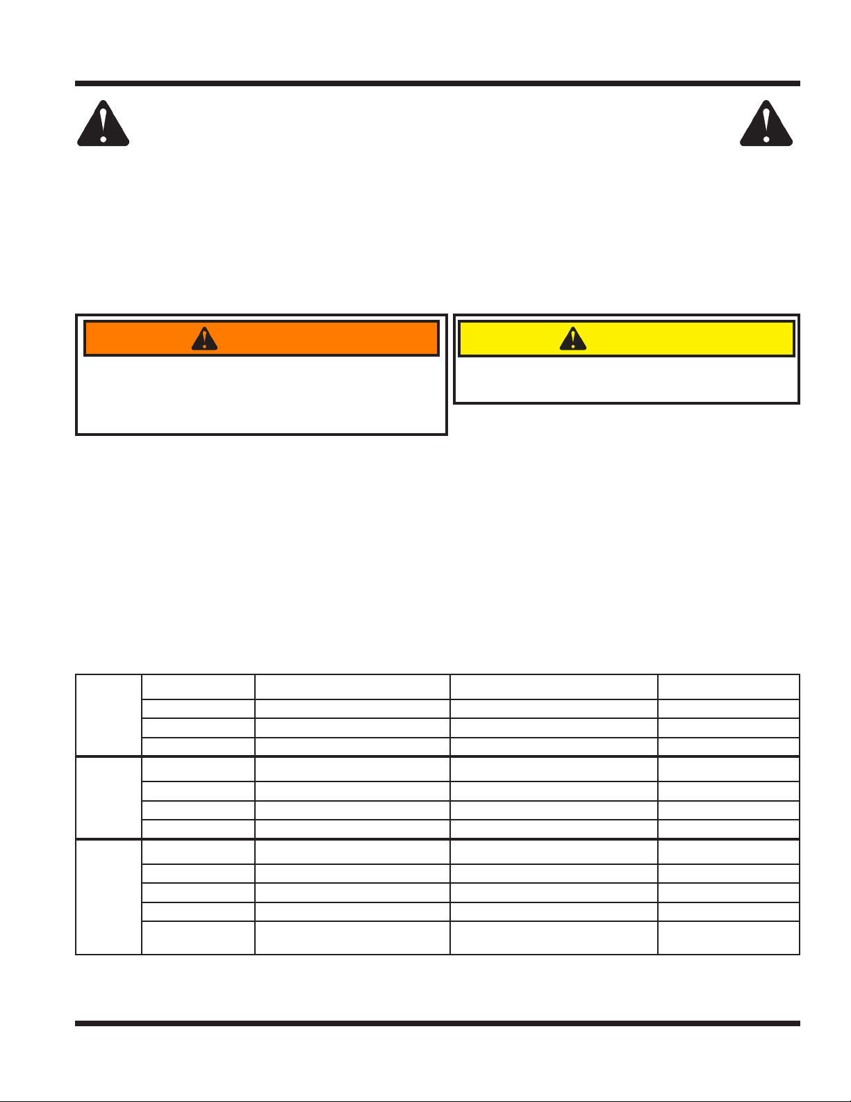
Testing the Safety Interlock System
WARNING
Never operate the power unit if the safety interlock
system is malfunctioning. Do not disengage or bypass
The daily inspection should be performed prior to
initial startup for the day.
CAUTION
any switch. Failure to heed warning could result in
injury to yourself and others, or damage to property.
Perform the following safety interlock tests daily. Before testing, park the power unit on a level surface,
place wheel chocks in front and back of wheels, and place the high/low range shift lever in the neutral
position. After testing is complete, place the high/low shift lever in either high or low range, set the parking
brake, and remove the wheel chocks.
Tests 1-3 test the ‘Engine Start’ function. For each test, turn the key to the RUN position (do not start the
engine). As listed for each test, engage or disengage the parking brake and sit on the seat or raise body
weight from seat. The engine starter should or should not engage as described for each test.
Tests 4-6 test the ‘Engine Run’ function. For each test, start the power unit so that the engine is running. As
listed for each test, engage or disengage the parking brake and sit on the seat or raise body weight from
seat. The engine should continue running or stop running as described for each test.
Tests 7-10 test the ‘PTO’ function. For each test, turn the key to the RUN position (do not start the engine).
As listed for each test, place the PTO switch in the ON or OFF position and sit on the seat or raise body
weight from seat. The electric PTO clutch will make an audible noise when it engages or disengages.
Test Number Parking Brake Engaged Operator Present in Seat Engine Starts
Engine
Start
Engine
Run
PTO
1 No Yes No
2 Yes No Yes
3 Yes Ye s Yes
Test Number Parking Brake Engaged Operator Present in Seat Engine Runs
4 Yes Ye s Yes
5 Yes No Yes
6 No No No
Test Number PTO Switch Operator Present in Seat PTO Clutch
7 O Ye s O
8 Pull to ‘On’ Position No No
9 Pull to ‘On’ Position Ye s Yes
10 On
Raise Operator Body Weight from
Seat
PTO Disengages
(1/2 second delay)
If the power unit fails any one of the safety interlock tests, refer to the troubleshooting section for using the
TCM (tractor control module) to diagnose electrical problems.
Safety - 19
OPERATIONAL CONTROLS
OPERATIONAL CONTROLS
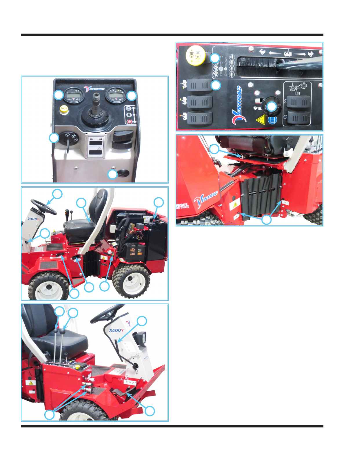
Standard Operational Control Locations
Use the following images to help identify the locations
of operational controls. The letter next to each control
can be referenced to the list that follows these images.
A
C
D
E
J
B
K
R
S
T
U
V
F
I
H
G
M
L
O
A. RPM/Hour Cluster Gauge
B. Fuel Cluster Gauge
C. Ignition Switch
D. Warning Alarm (Continuous)
E. Steering Wheel
F. Steering Tilt Adjustment Lever
G. Front Hitch Latch Lever
H. Weight Transfer Select Lever
I. Circuit Breaker & Battery Disconnect
J. Seat Belt
K. Fuel Shut-o Valve
L. Primary SDLA Control Lever
M. Secondary SDLA Control Lever
N. Foot Pedal
O. Selector Lever/Parking Brake
P. Auxiliary Hydraulic Quick Couplers
R. PTO Switch
S. Headlight Switch
T. Throttle Lever
U. Seat Latch Strap
V. Transaxle Neutral Levers
P
N
Operation - 20
OPERATIONAL CONTROLS
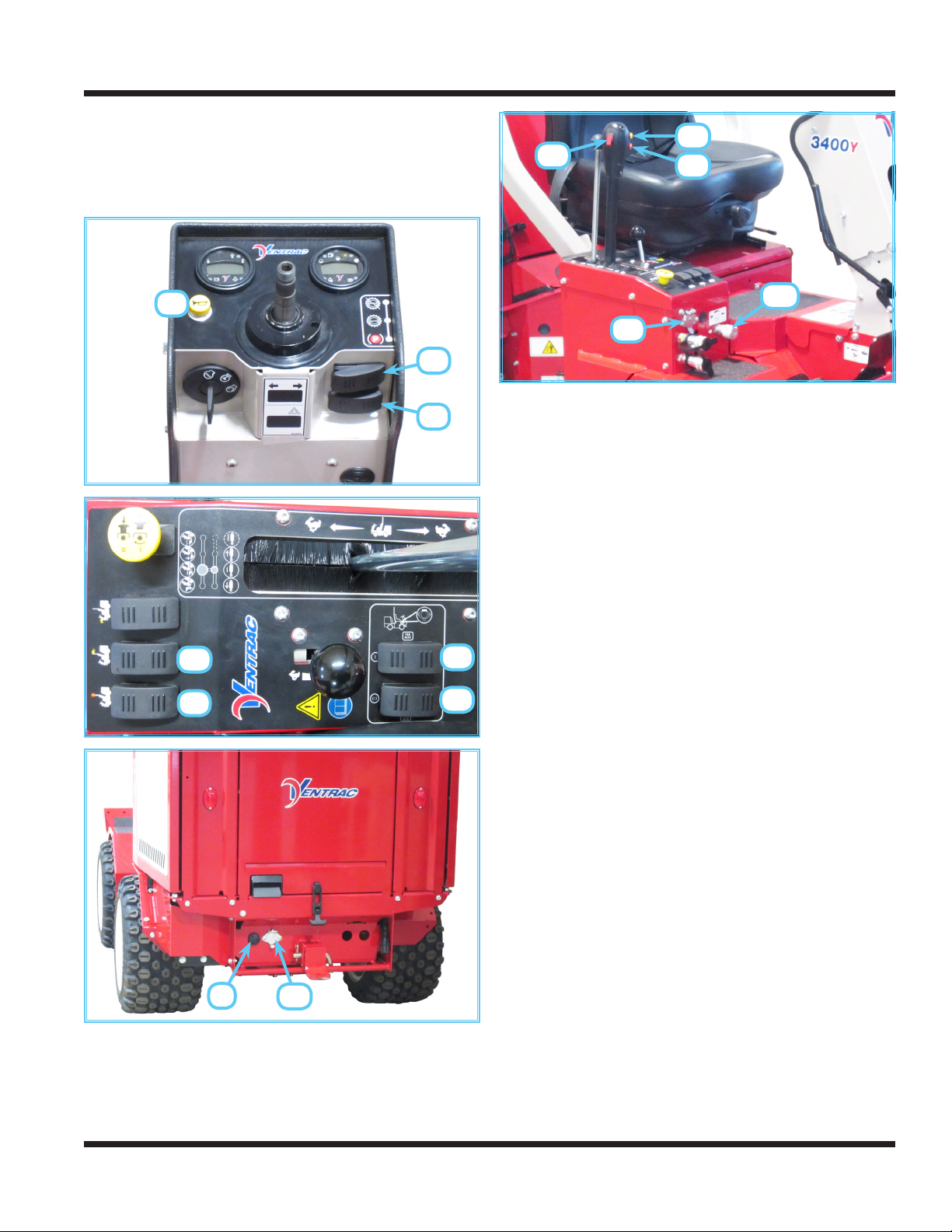
Optional Operational Control Locations
Use the following images to help identify the locations
of operational controls for optional kits. The letter
next to each control can be referenced to the list that
follows these images.
JJ
KK
KK
AA
DD
EE
BB
CC
FF
GG
MM
LL
AA. Horn Switch
BB. Directional Signal Switch
CC. Hazard Flasher Switch
DD. Work Light Switch
EE. Strobe Light Switch
FF. Rear 12V Switch (On/O)
GG. Rear 12V Switch (Momentary On/O/On)
HH. Rear 12V 4-Pin Socket
II. Back Up Alarm
JJ. Front 12V Switch (On/O)
KK. Front 12V Buttons (Momentary On)
LL. Front 12V 4-Pin Socket
MM. Front Hitch Valve
II
HH
Operation - 21
OPERATIONAL CONTROLS
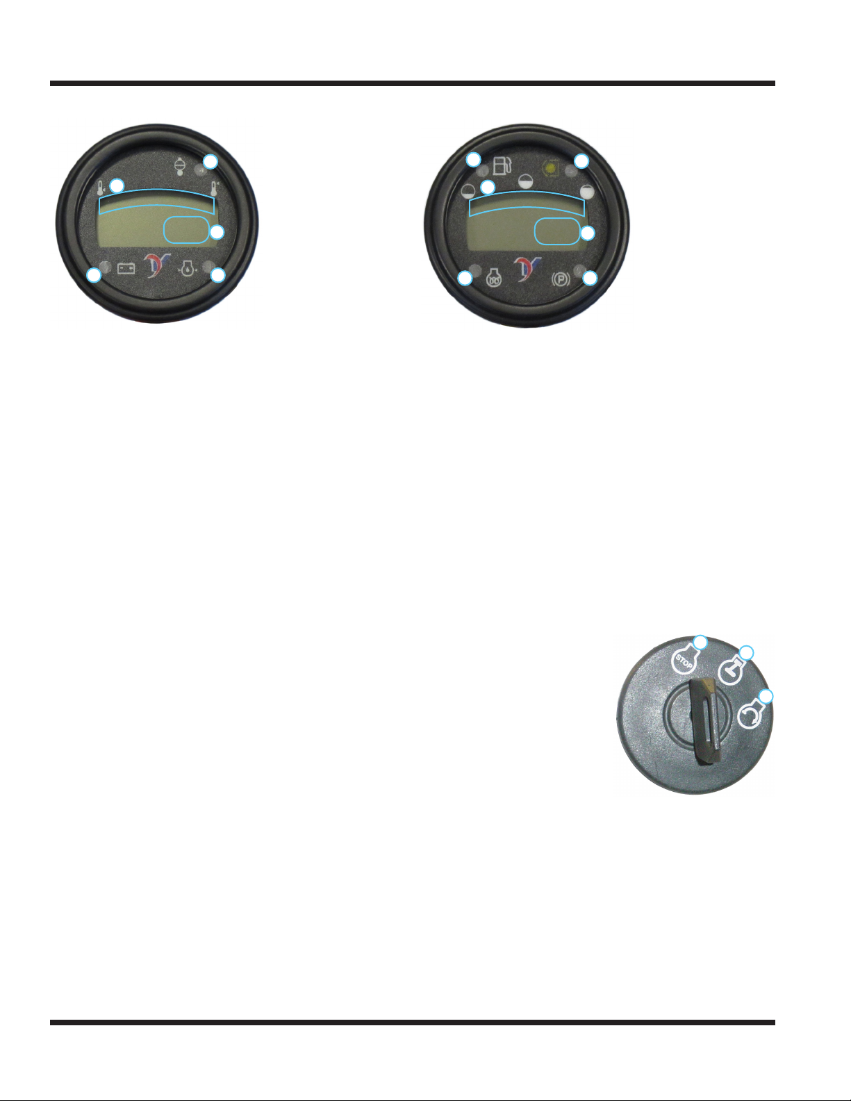
RPM/Hour Cluster Gauge (A)
1. Water Temperature
2
1
3
4 5
The water temperature gauge displays the temperature of the engine cooling system.
The water high temperature warning light and
audible alarm activate when the temperature of the
engine cooling system reaches unsafe levels. If this
light and alarm comes on during operation, park the
power unit, turn the PTO o, reduce engine speed
to low idle, and allow the engine to cool. Check the
radiator screen and clean, if necessary. If engine
temperature continues to rise, shut o the engine. If
the engine continually overheats, refer to the troubleshooting section for possible problems.
The tachometer / hour meter displays both the
engine run time and the engine speed. When
the engine is not running and the ignition switch
is turned to the On position, the gauge displays
the accumulated time the ignition key has been
switched to the On position. When the engine is running, the gauge displays the engine speed in RPM.
The low voltage warning light and audible alarm
activate when the voltage drops to unacceptable
levels. If this light and alarm comes on, shut o
any unnecessary lights and accessories to reduce
current draw. If voltage continues to drop, park the
power unit, shut o the engine, and turn the ignition
key to the o position. Refer to the troubleshooting
section for possible problems.
The low engine oil pressure warning light and
audible alarm activate when the engine oil pressure
is below safe levels. The light comes on when the
ignition key is switched to the on position and stays
illuminated until the engine is started and safe oil
pressure develops. If this light and alarm comes on
during operation, immediately shut o the engine.
Do not restart the engine until the problem has been
located and corrected.
Gauge
2. Water High Temperature
Warning Light
3. Tachometer / Hour Meter
4. Low Voltage Warning
Light
5. Low Engine Oil Pressure
Warning Light
Fuel Cluster Gauge (B)
1. Fuel Gauge
2
1
5
3
4
6
2. Low Fuel Warning Light
3. PTO Indicator Light
4. Speedometer
5. Glow Plug Indicator
Light
6. Park Brake Indicator
Light
The fuel gauge displays the level of fuel in the tank.
The low fuel warning light activates when the fuel
level is low.
The PTO indicator light activates when the power
unit’s PTO clutch is engaged.
The speedometer displays the speed of the power
unit. The speedometer can be set to display either
miles per hour (mph) or kilometers per hour (kph).
The glow plug indicator light indicates activation
of the glow plugs for preheating the engine. The
glow plugs activate when the key is turned to the
on position. When the glow plug light turns o, the
engine is ready to start.
The park brake indicator light activates when the
park brake is set.
Ignition Switch (C)
1.
O or Stop Position -
all 12 volt power going
through the key switch is
o.
2. On or Run Position engine run position, 12
volt power is sent to
accessories.
3. Start Position - when the
key is turned to the start
position, the starter will engage.
1
2
Warning Alarm (D)
The warning alarm works with the RPM/Hour
cluster gauge to alert the operator to problems.
The warning alarm sounds a continuous signal
whenever a warning is displayed on the RPM/
Hour cluster gauge. If the warning alarm sounds,
immediately check the RPM/Hour cluster gauge to
determine the cause of the warning and then take
appropriate action.
3
Operation - 22
OPERATIONAL CONTROLS
Steering Wheel (E)
Turn the steering wheel to the left (counterclockwise)
to turn the power unit to the left. Turn the wheel to the
right (clockwise) to turn the power unit to the right.
Steering Tilt Adjustment Lever (F)
Push down on the steering tilt adjustment lever to
release the adjustment lock. Tilt the steering column forward or backward to the desired position.
Release the steering tilt adjustment lever to lock the
steering column in place.
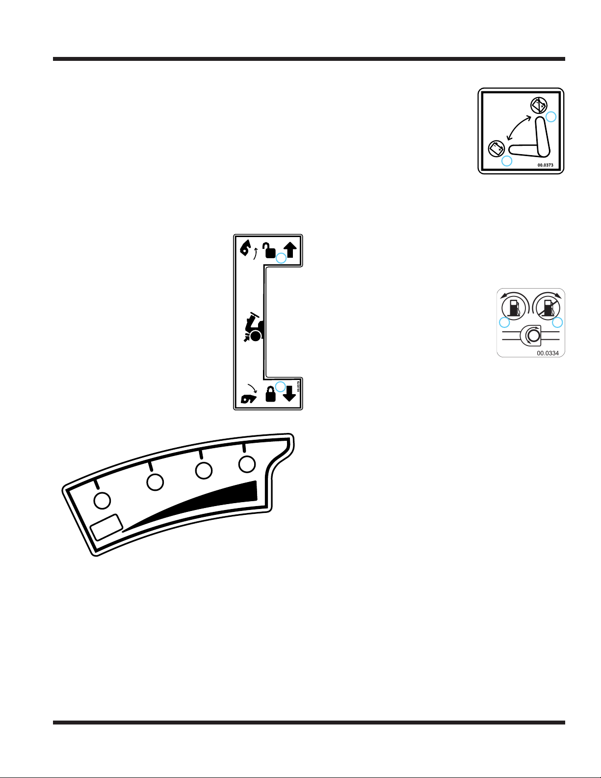
Front Hitch Latch Lever (G)
The front hitch latch lever
locks or unlocks the hitch
latch.
Rotate the front hitch latch lever
toward the front of the power unit to
unlock the hitch latch when attaching or detaching Ventrac attachments.
Rotate the front hitch latch lever
toward the rear of the power unit to
lock the hitch latch over the hitch
arm pins on Ventrac attachments.
Ensure the lever is secured in the
frame notch and the front hitch lever
lock is in place.
1. Unlocked
2. Locked
1
2
Weight Transfer Select Lever (H)
Circuit Breaker & Battery Disconnect (I)
The circuit breaker/battery
disconnect switch controls power
to the entire electrical system.
Turning the switch to position 0
disables the electrical system,
allowing electrical components
to be serviced.
Seat Belt (J)
Sit down on the seat and adjust
the seat to the desired position. Pull the seat belt
across your lap, ensure the seat belt is not twisted,
and insert the belt latch plate into the seat belt
buckle until it clicks. Pull up on the latch plate to
make sure it is secure. Pull on the loose end of the
seat belt to snug the seat belt across your lap.
0
1
0. Electrical Power O
1. Electrical Power On
Fuel Shut-o Valve (K)
The fuel shut-o valve controls the ow
of fuel to the power unit engine. Turning
the valve counterclockwise (1) to the
stop allows fuel to ow to the engine.
Turning the valve clockwise (0) to the
stop shuts o the fuel ow to prevent
fuel leakage when changing fuel lters
or servicing the fuel system. Turn o the fuel shut-o
valve when transporting the power unit on a truck or
trailer and when parking the power unit indoors.
1 0
0. Fuel O
1. Fuel On
3
00.0359
2
1
0
TC
The weight transfer system transfers weight from
the attachment to the front wheels of the power
unit. Transferring weight from the attachment to the
power unit increases the traction control, improves
hillside maneuverability, aids in lifting the attachment,
reduces steering eort, and lessens the attachment
resistance when in contact with the ground.
The operator can select dierent transfer rates by
selecting one of the four positions from no weight
transfer (0) to maximum weight transfer (3). Set the
weight transfer to 0 when attaching or detaching any
attachment.
Operation - 23

OPERATIONAL CONTROLS
SDLA Control Levers (L & M)
1. Forward Direction
2. Reverse Direction
3. Lift
4. Hold
5. Lower
6. Float
7. Direction #1
8. Hold
9. Direction #2
10. Float (if equipped)
The SDLA(Speed, Direction, Lift,
and
Auxiliary) is the primary control for the
power unit and consists of two levers. The
primary SDLA control lever (L) controls
the speed, direction of travel, and lift of
the hitch arms. The secondary SDLA
control lever (M) controls the auxiliary
hydraulic circuit.
S - Speed: the amount of forward or back-
ward movement of the primary SDLA
lever controls the ground speed of the
power unit.
D - Direction: the forward or backward
movement of the primary SDLA lever
controls the direction of the power unit.
L - Lift: the lift function of the primary SDLA
lever has four positions: Up, Hold,
Down, and Float Lock. “Hold” is the
default position; this holds the lift arms
from moving up or down. Pulling the
lever to the left raises the hitch arms.
Pushing the lever to the right lowers the
hitch arms. Float position is attained by
pushing the lever to the right until the
oat detent locks the lever in place.
A - Auxiliary: the left or right movement of
the secondary SDLA lever controls the
functions of attachments that require
the auxiliary hydraulic circuit. An
optional oat kit (part # 23.0111-7) is
available for the auxiliary circuit.
6543
10
987
Foot Pedal (N)
1
1. Reverse Direction 2. Forward Direction
The foot pedal works in conjunction with the SDLA
control lever and can be used to control the speed
and direction of the power unit when the operator’s
hand is removed from the SDLA lever.
Press down on the front portion of the foot pedal to
move the power unit in the forward direction. Press
down on the rear portion of the foot pedal to move
the power unit in the reverse direction. Changing the
amount the foot pedal is depressed will immediately
change the ground speed of the power unit.
To slow or stop (brake) the power unit, press down
on the opposite portion of the foot pedal (i.e. if you
1
are traveling forward, press down on the rear portion of the foot pedal).
2
Selector Lever/Parking Brake(O)
When parking the
power unit, always
move the selector
lever to the parking brake position (1) to prevent
accidental movement of the machine.
To engage the parking brake,
pull the selector lever back
toward the operator.
If the operator leaves the seat without
rst setting the parking brake, the
power unit will shut o the engine. The
foot pedal and the SDLA control lever
2
are locked from forward or reverse movement when
the selector lever is in the parking brake position.
Placing the selector lever in the neutral assist (auto)
position (2) engages the neutral assist spring to help
return the SDLA control levers to the neutral position.
This makes the neutral position easy to select and
maintain. The neutral assist (auto) position is recommended when learning the operation of the power
unit, loading or unloading, attaching and removing
attachments, and whenever the operator is unsure of
the power unit’s response to the task being performed.
Placing the selector lever in the neutral assist o
position (3) disengages the neutral assist spring. This
position is designed for experienced operators when
1. Park Brake
2. Neutral Assist (auto)
3. Neutral Assist O
3
2
1
Operation - 24

OPERATIONAL CONTROLS
using the power unit in open areas where travel
speed and direction are relatively constant and
control is easily maintained. The neutral assist o
position reduces operator arm fatigue when using the
power unit for prolonged periods of time.
CAUTION
Stopping the power unit with the neutral assist
lever in the o position requires the operator to
manually return the SDLA control lever or foot
pedal to the neutral position.
Auxiliary Hydraulic Quick Couplers (P)
The two couplers are a part of the auxiliary hydraulic circuit and are used with an attachment which
requires hydraulics (e.g. to angle a dozer blade or
rotate the discharge on the snow blower).
Power Take O (PTO) Switch (R)
Pulling up on the PTO switch
engages the electric clutch to provide
power to the front attachment.
Pushing down on the PTO switch
disengages the electric clutch and
applies the clutch brake to stop the
attachment. NOTE: the PTO will turn
o automatically if the operator leaves
the seat. The PTO can be restarted by
turning the PTO switch o and then on again.
Headlight Switch (S)
Pressing the front (1) of the head
light switch turns the headlights and
taillights on. Pressing the back (0) of the
switch turns the lights o.
Throttle Lever (T)
2
10
0. PTO O
1. PTO On
0. O
1
1. On
1. Slow
2. Fast
1
0
To release the seat so that it can be tilted forward
for service, remove the linch pin and lift the tab on
the seat latch strap o the seat latch pin.
Transmission Neutral Levers (V)
CAUTION
Never shift the transaxles to neutral while under
load, while moving, or while on a slope.
Always place the selector lever in the parking
brake position while shifting into neutral.
Always re-engage both transaxle levers when
pushing or towing of power unit is complete.
0
0. Neutral 1. Transaxle Engaged
In the event the power unit must be pushed or
towed, both the front and rear transaxles must be
shifted into neutral position. Lift up on each lever,
pull the lever out toward you until the tab clears the
frame, and lower the lever back into the frame notch
to secure in the neutral position. NOTE: insert a
screwdriver or other tool through the hole in the lever
to aid in pulling the lever out to the neutral position.
Horn Switch (AA)
Press the horn switch to
1. Horn
Signal
sound the signal horn. The
horn will sound until the
horn switch is released.
Directional Signal Switch (BB)
1. Left Turn Signal
1 2
2. Right Turn Signal
1
1
Moving the throttle lever forward toward the fast position (2) increases the engine Revolutions Per Minute
(RPM). Moving the throttle lever backward toward the
slow position (1) decreases the engine RPM.
Seat Latch Strap (U)
The seat latch strap secures the seat during transport of the power unit.
To secure the seat, place the tab on the end of the
seat latch strap over the seat latch pin. Install the
linch pin through the hole in seat latch pin to secure.
Operation - 25
Pressing the left portion of the directional signal
switch turns the left turn signal on. Pressing the
right portion of the directional signal switch turns the
right turn signal on. Return the switch to the middle
position to turn the signals o. The left and right turn
signals will override the hazard ashers.

OPERATIONAL CONTROLS
Hazard Flasher Switch (CC)
0. Hazard Flasher O
1. Hazard Flasher On
0 1
Pressing the right portion of the hazard asher
switch ashes both directional turn signal lights.
Pressing the left portion of the switch turns the
hazard asher lights o. Use of the directional turn
signals will override the hazard ashers until the
turn signals are turned o.
Work Light Switch (DD)
Depressing the front (1) of the
work light switch turns the work
0. O
1. On
1
lights on. Pressing the back (0) of the switch
turns the work lights o.
Strobe Light Switch (EE)
Pressing the front (1) of the
strobe light switch turns the strobe
0. O
1. On
0
1
light on. Pressing the back (0) of the switch
turns the strobe light o.
0
12 Volt Rear Switches & 4-Pin Socket (FF, GG, & HH)
The rear 4-pin socket
provides electrical power
to rear mounted attachments that are equipped
with electrical controls.
(e.g. ES220 Spreader)
The switches turn on and
o the electrical power to
the rear 4-pin socket.
Pressing the left portion
(1) of the on/o switch
turns electrical power
to the 4-pin socket on.
Pressing the right portion
(0) of the switch turns
electrical power o.
Pressing the left (2) or
right (3) portion of the momentary on/o/momentary
on switch turns electrical power to the 4-pin socket
on. Releasing the switch turns electrical power o.
1
2
0. O
1. On
2. Momentary On
3. Momentary On
0
3
12 Volt Front Switches & 4-Pin Socket (RR, SS, & TT)
The front 4-pin socket
provides electrical
power to attachments
that are equipped with
electrical controls.
(e.g. broom rotation
actuator)
The switches turn on
and o the electrical
power to the front 4-pin socket.
Pressing the top portion (1) of the
on/o switch turns electrical power
to the 4-pin socket on. Pressing
the bottom portion (2) of the switch turns electrical
power o.
Pressing either the top (3) or bottom (4) momentary
on switch turns electrical power to the 4-pin socket on.
Releasing the switch turns electrical power o.
1
0
0. O
1. On
2. Momentary On
3. Momentary On
2
3
Front Hitch Valve (MM)
The front hitch valve
is used to control the
lowering of the front
hitch.
Turning the knob on
the front hitch valve
counterclockwise
increases the speed at which the front
hitch and attachment can be lowered.
Turning the knob clockwise decreases the speed at
which the front hitch and attachment can be lowered.
The front hitch and attachment can be locked in any
position so that it will not lower, by turning the front
hitch valve knob clockwise until it is completely closed.
2
1
1. Slow/Locked
2. Fast
Operation - 26

GENERAL OPERATION
Daily Inspection
Always set the parking brake, shut o power
unit engine, remove the ignition key, and ensure
all moving parts have come to a complete stop
before inspecting components, or attempting
any repair or adjustment.
1.
Park power unit on a level surface, with the
engine shut o and all uids cold.
2. Perform a visual inspection of the power unit.
Look for loose or missing hardware, damaged
components, or signs of wear.
3. Inspect the ROPS structure and seat belt for
damage or signs of wear.
4. Inspect the battery, electrical connections, and
lights.
5. Ensure parking brake tension is properly adjusted.
6. Inspect hydraulic hoses, hydraulic ttings, and
fuel lines to ensure tight, leak free connections.
7. Inspect belts for damage or excessive wear.
Service as required.
8. Check the power unit’s engine oil level, hydraulic
oil level, coolant level, and fuel level. Add uid or
service as required.
9. Ensure the radiator screen and engine compart-
ment are clean. Inspect the air lter restriction
gauge.
10. Check tires for proper ination.
11. Test the operator safety interlock system.
Starting The Engine
CAUTION
Do not use ether or starting uids. Use of starting
uids in the air intake system may be potentially
explosive or cause a runaway engine condition.
Use of starting uids could result in engine damage and/or personal injury.
CAUTION
Allow time for hydraulic oil to circulate before operating the power unit. Severe damage could result to the
hydraulic system if adequate warm up isn’t allowed.
Warm up time is increased in colder weather.
The 3400 is equipped with an interlock system for
operator safety. The safety interlock system requires
the parking brake to be engaged.
1. Turn the fuel shut-o valve to the On position.
2. Turn the battery disconnect switch to the On
position.
3. Move the throttle lever to just past the half
throttle position.
4. Turn the ignition key to the run position to activate
the glow plugs for preheating the combustion
chamber. When the glow plug indicator light turns
o, the engine is ready to start. If the engine is
at operating temperature, the engine does not
need to be preheated. If the ambient temperature
is below 23° F (-5° C), the preheating cycle may
need to be repeated prior to starting.
Do not run the electric starter continuously for
more than 10 seconds. If the engine does not
start right away, wait 30 seconds and try again.
5.
Turn the ignition key to the start position and
hold to engage the starter. Release the key
when the engine starts. NOTE: if engine fails to
start, refer to the troubleshooting section.
6. The engine and hydraulic oil must be warmed to
operating temperature before operations. Allow
the unit to run at approximately 1800 rpm until
the hydraulic lter is warm to touch. The hydraulic lter is located at the right rear of the front
frame, below the front transaxle neutral link.
Operation - 27
CAUTION

GENERAL OPERATION
Forward And Reverse
Verify that the intended path is safe and free from
obstacles. Set the selector lever to the desired posi-
tion (Neutral Assist Auto or Neutral Assist O).
WARNING
Never remove your right hand from the SDLA
control lever unless you are using the foot pedal to
control speed and direction. All direction, speed, and
braking are controlled by the SDLA lever or the foot
pedal. Depending on the terrain or rate of speed,
more force may be required to maintain speed,
change direction, or brake. Your hand or foot must
always be ready to brake or stop the power unit.
Power unit movement is
controlled by moving the
SDLA control lever in the
desired direction of travel.
Push the SDLA control lever
forward to move power unit in
the forward direction. Pull the
SDLA control lever backward
to make the power unit move
in the reverse direction.
Changing the amount the
SDLA control lever is moved,
instantly changes the ground
speed of the power unit.
Moving it one half of the stroke
will result in approximately one
half of the maximum ground
speed. Moving it to the end of
the stroke will result in maximum ground speed.
The foot pedal can be used to control speed
and direction instead of the SDLA control lever.
The SDLA control should be used for precision control in tight spaces or when connecting an attachment. The foot pedal is better suited to controlling
speed and direction in open areas.
0. Neutral
1. Forward
2. Reverse
Stopping The Power Unit
To slow or stop the power unit, move the SDLA control
lever or foot pedal in the opposite direction that you
are traveling. Return the SDLA control lever or foot
pedal to the neutral position to make a complete stop.
If in the case of an emergency, the power unit cannot
be stopped with the SDLA control lever, pull back the
selector lever to engage the parking brake.
CAUTION
If the parking brake is engaged while the power
unit is moving, the engine will shut o and the
power unit will come to an abrupt stop.
1
Shutting O The Engine
1. Park the power unit on a level surface and set
the parking brake.
2. Move the throttle lever to the slow idle position.
0
3. Allow the engine to idle for 3-5 minutes.
4. Turn the ignition key to the o position and
remove the key from the ignition switch.
5. When parking the power unit at the end of the
2
day, turn the battery disconnect switch and the
fuel shut-o valve to the O positions.
Attaching
1. Drive the power unit slowly forward into the hitch
arms of the attachment. Align the lift arms of the
power unit with the attachment hitch arms by
raising or lowering the front hitch and complete
the engagement.
2. Once completely engaged, move the front hitch
latch lever to the locked position.
3. Engage the parking brake and shut o the engine.
4. Place the attachment belt onto the PTO drive
pulley on the power unit. Ensure the belt is properly seated in each pulley.*
5. Engage the attachment’s PTO belt tensioner.*
6. Wipe the attachment’s hose ends clean, and connect to the power unit’s hydraulic quick couplers.*
If equipped, connect the hoses and quick couplers so the red indicators are paired together
and the yellow indicators are paired together.
7. Connect the electric plug to the matching socket.*
Refer to attachment manual for additional details.
*Applies only if the attachment is equipped.
Operation - 28

GENERAL OPERATION
Detaching
1. Park the power unit on a level surface and set
the parking brake.
2. Fully raise the front hitch and attachment and
set the weight transfer to 0.
3. Lower the attachment to the ground and place
the primary SDLA lever in the oat position.
4. Shut o power unit engine.
5. Disengage the attachment’s PTO belt tensioner.*
6. Remove the attachment belt from the PTO drive
pulley of the power unit.*
7. Move the secondary SDLA lever left and right to
release pressure from the auxiliary hydraulic circuit and disconnect the hydraulic quick couplers
from the power unit.*
8. Disconnect the electric plug from the socket on
the power unit.*
9. Move the front hitch latch lever to the unlocked
position.
10. Restart the power unit and slowly back away
from the attachment.
Refer to attachment manual for additional details.
*Applies only if the attachment is equipped.
Operating Attachments
Refer to the operator’s manual for each attachment
for the proper operation and use of the particular
attachment that is being operated.
Front Hitch
The front hitch is used to secure attachments to power
unit, and to raise and lower the attachment. The front
hitch is controlled by the primary SDLA lever. Pull the
lever to the left to raise the attachment, push the SDLA
lever to the right to lower the attachment. The primary
SDLA is equipped with a ‘oat’ position. Push the
SDLA lever to the far right position until the oat detent
engages and stays in place to operate in oat.
PTO Drive Belt & Pulley
If
the attachment requires a drive belt, release the
attachment’s PTO belt tensioner and install the
attachment belt
around the drive
pulley at the
location shown
above. When the
belt is in place
around the drive
pulley, engage the
attachment’s PTO
belt tensioner.
PTO drive pulley
Front Auxiliary Couplers
CAUTION
EQUIPMENT DAMAGE!
Dirt and other debris in hydraulic system can cause
damage to the system. Wipe clean the mating parts
of the couplers before coupling. Use protective rubber plugs over hydraulic couplers when not in use.
If attachment requires auxiliary hydraulics, couple the
attachment hoses with the front auxiliary couplers.
This is done by sliding the collar of the coupler rearward and inserting the end of the attachment hose into
the coupler and releasing the collar. If the collar will not
snap forward on its own, pull it forward manually.
The couplers that the hoses are attached to will
aect which way the secondary SDLA lever is
pushed to control the action of the attachment. If the
attachment is equipped with red and yellow indicators, connect the hoses and quick couplers so the red
indicators are paired together and the yellow indicators are paired together. If the hoses are connected
and the action is not the desired motion, then switch
the hoses the couplers are attached to.
Auxiliary couplers are controlled by moving the secondary SDLA lever left or right.
NOTE: Pressure build-up in the attachment hose
and the power unit couplers may occur, causing
dicult installation of hoses. If hoses do not easily
connect, try one or both of the following steps:
1. To release the pressure from power unit cou-
plers, turn o engine and move the secondary
lever of the SDLA right and left to release pressure in the power unit’s hydraulic circuit.
2. To release pressure in the attachment hose,
loosen one of the hose ends and retighten when
pressure is released.
WARNING
Hydraulic uid is under high pressure and
can penetrate skin, causing injury. Keep
hands, face, and body away from pinholes
or nozzles that eject hydraulic uid under
high pressure.
Operation - 29

GENERAL OPERATION
Weight Transfer
The weight transfer system transfers weight from the
attachment to the front wheels of the power unit when
the front hitch is in oat or assists in lifting the attachment. Transferring weight from the attachment to the
power unit increases the traction control, improves
hillside maneuverability, aids in lifting the attachment,
reduces steering eort, and lessens the attachment
resistance when in contact with the ground.
The operator can select dierent transfer rates by
selecting one of the four positions from no weight
transfer (0) to maximum weight transfer (3). Set the
weight transfer to 0 when attaching or detaching any
attachment.
To set the weight transfer, raise the front hitch to
its maximum height and move the weight transfer
select lever to the desired position.
Selecting the proper amount of weight to transfer
depends on attachments, ground conditions, and
operator preference. A lightweight attachment (e.g.
LA162 power blower) will not go down with full
weight transfer on. With full weight transfer on, and
mowing in the oat position, the mower may not
come down quickly enough when going through
uneven terrain. Power unit speed or weight transfer
rate must be reduced.
Roll-Over Protection System (ROPS)
WARNING
Keep the ROPS locked in the upright position and
the seat belt securely fastened during operation.
Failure to do so could result in serious injury or
loss of life.
2. Fold the roll bar down and install the pins in the
rear holes (2) of the hinge plates to lock in place.
1
2
1. Locked Upright 2. Locked Folded Down
To raise the roll bar:
1. Remove the pins from the rear holes (2) of the
right and left hinge plates.
2. Raise the roll bar to the upright position and install
the pins in the front holes (1) of the hinge plates to
lock in place.
12 Volt 4-Pin Auxiliary Outlets (Optional Accessory)
Certain attachments require a 12 volt auxiliary
outlet. Plug the attachment’s 12 volt power cord into
the 12 volt 4-pin outlet. The actions of the front 12
volt outlet are controlled by an on/o switch and two
momentary on buttons on the SDLA handle. The
actions of the rear 12 volt outlet are controlled by an
on/o switch and a momentary on/o/on switch on
the side dash panel beside the SDLA control. The
momentary buttons or switch are used for controlling movement that is only used for a brief time. The
on/o switches are used to activate equipment or
select dierent functions.
The 3400 is equipped with a fold down ROPS that
allows the power unit to access areas of low overhead clearance. Lower the roll bar only when absolutely necessary and raise the roll bar to the upright
position as soon as clearance allows.
WARNING
Do not wear a seat belt when the roll bar has
been lowered to the down position.
To lower the roll bar:
1. Remove the pins from the front holes (1) of the
right and left hinge plates.
Operation - 30

GENERAL OPERATION
Operating On Slopes
WARNING
AVOID PERSONAL INJURY!
• Operation on slopes decreases power unit
stability and increases the potential for unex-
pected diculties. Only experienced operators
should operate the power unit on slopes and
extra caution should be exercised.
• Do not exceed the maximum degree of operation of 20°.
• Avoid uneven, loose, or wet terrain.
• Stay clear of drop-os, holes, ditches, rocks,
or objects that could cause a sudden and/or
unexpected force on the power unit.
• Make slow and cautious starts, stops, and turns.
• Turn downhill when possible and/or reduce
the degree of turns.
• Assure a sucient supply of fuel for continuous operation. A minimum of one-half tank of
fuel is recommended.
• To prevent fuel spillage, do not remove the
fuel tank cap while power unit is on a slope.
• Failure to follow items listed or to use common sense while operating on slopes can
result in injury or death. Always operate on
slopes with caution.
Maintain sucient fuel in tank to ensure continuous
operation.
Cease operation if power unit stability is question-
able, or if the operator is uncomfortable or unsure
of continuing safely. Do not operate on slopes
greater than 20°.
Attachments can aect the stability of the power unit.
Each attachment will aect the power unit dierently.
Operation in Water, Mud, Snow, or Ice
WARNING
Operation in water, mud, snow, or ice decreases
power unit traction and increases the potential for
unexpected diculties or loss of control. Reduce
speed and exercise caution.
WARNING
Operation on frozen bodies of water can be
dangerous. The machine could fall through the ice
and cause the operator to drown. Never operate
on ice unless you have veried the thickness of
the ice and that the travel path is safe.
CAUTION
Operation in water may cause damage to the
hydraulic system, axles, or other parts. If the water
level reaches the tire rim, the water is too deep.
Towing Or Pushing The Power Unit
Attention
Avoid damage to your power unit! Before towing, read and understand the information below.
Severe damage will occur to unit if proper towing procedure is not followed.
CAUTION
Failure to place the transaxles in neutral when towing or pushing the power unit may result in damage
to the power unit drivetrain.
Attention
Some attachments or accessories have further limitations on maximum angle of operation. Refer to individual attachment operator’s manuals for limitations.
Increase the amount of weight being transferred to
the power unit from the attachment while operating
on slopes. Refer to Weight Transfer section.
Always operate carefully and in a manner that does
not compromise safety.
Always keep the roll bar in the upright, locked position
and fasten yourself securely with the seat belt!
Operation - 31
I
f the power unit needs to be moved without the
engine running, it is important to remember to place
the transaxles in neutral by pulling both front and rear
transaxle neutral levers out to the neutral position.
With the transaxles in neutral and the parking brake
disengaged, the power unit can freewheel. This function is designed for slow, level, short distance towing
only. Use extreme caution when towing or pushing the
power unit; steering may not function.
Always re-engage both transaxle neutral levers when
towing is complete to prevent a freewheeling hazard if
the parking brake is released.

SERVICE
Always set the parking brake, shut o power
unit engine, remove the ignition key, and ensure
all moving parts have come to a complete stop
before inspecting components or attempting any
repair or adjustment.
Attention
Ventrac recommends that service be performed
by a qualied technician. If you are unsure how
to perform the service procedure(s), contact your
Ventrac dealer.
Cleaning And Appearance Care
For best results, and to maintain the nish of the
power unit, clean or wash the power unit to remove
accumulated clippings, leaves, dirt, gravel, and salt
deposits when the job is nished.
Attention
To maintain the nish of the power unit, thoroughly wash
the equipment after each use to remove any corrosive
agents (e.g. salt). Failure to clean the equipment may
result in corrosion of (including but not limited to) steel,
aluminum, and electrical components. Equipment that
will experience repeated exposure to corrosive agents
should be pretreated with a corrosion preventative.
Attention
If any component requires replacement, use only
original Ventrac replacement parts.
Service And General Maintenance
Proper and timely service of this power unit is
critical to keep the power unit in a safe and reliable
operating condition. Follow the maintenance schedule at the end of the service section. For convenience, a frequent service guide decal and a quick
reference chart decal have been placed on the
power unit inside the left hood panel.
CAUTION
If the engine has been running, it must be allowed
to cool in order to prevent damage to the block
and exhaust manifold.
Do not direct high pressure water at the engine,
air cleaner, muer, radiator, hydraulic oil cooler,
or any electrical components.
Allow the power unit and all components to cool
before washing. Refer to the specic service sections
for proper cleaning techniques for the engine and
radiator. Use mild soap and water to clean the power
unit. Harsh chemical cleaners could cause damage
to the nish or components.
After cleaning, use touch up paint to repair scrapes.
Service - 32

SERVICE
Service Access Points
Throughout the service section, dierent access
points are referred to. The following list and images
identify shields and covers that may need to be
removed or opened during service.
4
2
3
1
6
7
1. Left Hood Panel
2. Seat
3. Tunnel Access Cover
4. Engine Drive Belt Cover
5
5. Front Frame Canvas
6. Left Center Pivot Canvas
7. Weight Transfer Access Cover
13
14
15
13. Top Center Pivot Guard
14. Left Center Pivot Guard
15. Right Center Pivot Guard
Lubrication Locations
Lubrication is required at the
following locations. Refer to the
maintenance schedule for service
intervals and amount of grease. Refer to
Specications section for grease type.
Front of Lift & Steering Cylinders
Grease
Silicon Based
Spray Lube
9
8. Top Hood Panel
9. Right Hood Panel
8
10
11
10. SDLA Access Cover
11. Right Center Pivot Cover
12
Rear of Steering Cylinder
12. Rear Panel
Service - 33

SERVICE
Lubrication Locations (Cont.)
SDLA Pivot & Rear of Lift Cylinder
The rear grease tting on the lift cylinder must be
greased from below the cylinder by removing the
weight transfer access cover and using a grease gun
with a exible hose.
Connector Link
Checking Hydraulic Oil Level
Check the hydraulic oil level when the hydraulic
system is cold, prior to operating the power unit. If
the hydraulic system is warm, allow one hour for the
hydraulic system to cool before checking the oil level.
Checking the oil level when the hydraulic system is
warm will produce an inaccurate oil level reading.
Attention
After connecting a new attachment or kit that runs
o the power unit’s hydraulic system, run the attachment through a complete cycle, then stop and check
the hydraulic oil level.
1.
Park the power unit on a level surface and adjust
the steering to aim the power unit straight ahead.
2. Fully raise the front hitch.
3. Engage the parking brake and shut o the engine.
4. Remove the key from the ignition switch and
allow time for the hydraulic system to cool.
5. The hydraulic oil tank (A) is located under the
top hood panel at the front right corner of the
rear frame.
Center Pivot
Seat Slides
6. ACheck the oil level in the hydraulic oil tank. The
oil level should be centered between the low and
full marks on the hydraulic oil tank. NOTE: use a
ashlight to inspect level if necessary.
7. If the hydraulic oil level is low, add HydroTorq
XL synthetic hydraulic oil until the proper level is
reached.
Service - 34

SERVICE
Changing Hydraulic Oil Filter
1. Park the power unit on a level surface.
2. Engage the parking brake and shut o the engine.
3. Remove the key from the ignition switch and
allow time for the hydraulic system to cool.
WARNING
Hot oil can cause severe burns. Allow the hydraulic
oil temperature to drop from hot to warm before
changing the oil lter.
4.
Clean the hydraulic lter (A), the lter head, and
the area around the hydraulic lter.
12. Shut o the power unit engine and allow the
power unit to sit for a minimum of ve minutes.
13. Check the hydraulic oil level and add HydroTorq
XL synthetic hydraulic oil, if necessary. Refer to the
manual section for checking hydraulic oil level.
14. Inspect the hydraulic lter for signs of leakage.
If any leaks are evident, the lter may need
tightened further, or the lter may need to be
removed, the gasket and lter mount cleaned,
and the lter reinstalled following the procedures
for changing the lter.
Changing Hydraulic Oil
1. Wash the underside and sides of both the front
and rear transaxles thoroughly.
2. Park the power unit on a level surface and adjust
the steering to aim the power unit straight ahead.
3. Fully raise the front hitch.
4. Engage the parking brake and shut o the engine.
5. Remove the key from the ignition switch and
allow time for the hydraulic system to cool.
WARNING
5. APlace a small drain pan under the hydraulic lter.
6. Use a lter wrench to unscrew the hydraulic lter
from the lter head and allow the oil to drain into
the pan.
7. Ensure the lter mounting surface is clean.
8. Apply a thin lm of clean oil to the gasket of the
new lter and screw the lter onto the lter head
until the gasket makes contact with the mount-
ing surface. Tighten the lter an additional 1 turn
(may require using a lter wrench).
9. Clean up any spilled oil and dispose of oil and
lter in accordance with local laws.
CAUTION
Oil is hazardous to the environment. Drain oil into
an approved container and dispose of used oil in
accordance with local laws.
10.
If hydraulic oil is being changed at the same
time as the lters, skip the remaining steps and
proceed to Changing Hydraulic Oil section.
11. Start the power unit and let it run at low idle
engine speed for several minutes. Turn the steering wheel to the left and right a couple of times to
purge any trapped air out of the hydraulic system.
Hot oil can cause severe burns. Allow the hydraulic
oil temperature to drop from hot to warm before
draining the hydraulic oil.
6.
Remove the front transaxle skid plate from the
power unit.
7. Place a drain pan (minimum 7 quart / 6.5 liter)
under the front transaxle drain.
8. Remove the drain plug (A) from the front transaxle and allow the hydraulic oil to drain from the
system. Loosen the cap on the hydraulic oil tank
to allow venting.
9. AClean the drain plug, reinstall into the front
transaxle, and torque to 22 ft-lbs (30 Nm).
Service - 35

SERVICE
10. If hydraulic lter is being changed with the oil,
proceed to Changing Hydraulic Oil Filter section before completing the remaining steps in
this section.
11. Clean up any spilled oil and dispose of oil and
lter in accordance with local laws.
CAUTION
Oil is hazardous to the environment. Drain oil into
an approved container and dispose of used oil in
accordance with local laws.
12.
Reinstall the front transaxle skid plate onto the
power unit. Torque bolts to 31 ft-lbs (42 Nm).
13. Add HydroTorq XL synthetic hydraulic oil to the
hydraulic oil tank until the oil level is centered
between the low and full marks on the oil tank.
14. Start the power unit and let it run at low idle
engine speed for several minutes. Turn the steering wheel to the left and right a couple of times to
purge any trapped air out of the hydraulic system.
15. Shut o the power unit engine and allow the
power unit to sit for a minimum of ve minutes.
16. Check the hydraulic oil level and add HydroTorq
XL synthetic hydraulic oil, if necessary. Refer to the
manual section for checking hydraulic oil level.
Changing Rear Transaxle Dierential Oil
1. Remove the rear transaxle skid plate from the
power unit.
2. Place a drain pan (minimum 4 quart / 3.8 liter)
under the rear axle drain.
3. Remove the drain plug (A) from front of the rear
transaxle and allow the hydraulic oil to drain
from the transaxle.
4. Remove the plug (B) on the right side of the
transaxle to allow venting.
C
B
5.
Clean the drain plug, reinstall into the rear transaxle, and torque to 22 ft-lbs (30 Nm).
6. The rear transaxle can be lled through either
the port (B) on the right side of the transaxle or
by removing the vent plug (C) from the top of the
transaxle, using either a funnel with a exible
spout or a funnel inserted into a piece of 7/16”
outside diameter exible tubing.
7. Add HydroTorq XL synthetic hydraulic oil
(approximately 3 qt / 2.8 L) to the rear transaxle
until level with the bottom of the side port (B).
8. Reinstall the side plug and the top vent plug (if
removed) into the rear transaxle and torque to
22 ft-lbs (30 Nm).
9. Clean up any spilled oil and dispose of oil and
lter in accordance with local laws.
CAUTION
Oil is hazardous to the environment. Drain oil into
an approved container and dispose of used oil in
accordance with local laws.
10.
A
Reinstall the rear transaxle skid plate onto the
power unit. Torque bolts to 210 in-lbs (24 Nm).
Checking Engine RPM
Check engine RPM when engine is warmed up and
not under load. Observe tachometer:
• Low idle speed = 1625 ±25 RPM
• High idle speed = 2825 ±25 RPM
If engine RPM is incorrect, contact your local Ventrac dealer.
Service - 36

SERVICE
Checking Engine Oil Level
Attention
Avoid Engine Damage!
Failure to check the oil level regularly could lead to
serious damage to your engine, if the engine is run
with an incorrect oil level.
• Check the engine oil level with the power unit
sitting on a level surface and with the engine
shut o and the oil cold.
• Keep oil level between the FULL and ADD marks.
• Do not add oil with the engine running.
1.
Park the power unit on a level surface.
2. Engage the parking brake and shut o the engine.
3. Remove the key from the ignition switch and
allow the engine and oil to cool.
4. Remove the top hood panel to access the
engine compartment.
5. Remove the oil dipstick (A) from the engine and
wipe with a clean cloth.
D
Changing Engine Oil And Filter
CAUTION
Contact with engine oil can irritate your skin. Wear
protective gloves when working with engine oil.
If you come in contact with engine oil, wash it o
immediately.
CAUTION
Oil is hazardous to the environment. Drain engine
oil into an approved container. Dispose of used
engine oil in accordance with local laws.
1.
Start the power unit engine and allow it to run
until the engine reaches operating temperature.
2. Park the power unit on a level surface.
3. Engage the parking brake and shut o the engine.
4. Remove the key from the ignition switch.
5. Remove the top hood panel to access the
engine compartment.
6. Place a drain pan below the oil drain (A) located
underneath the rear frame just inside the left
rear wheel.
A
6.
Insert the dipstick back into the engine and
remove again.
7. Check the oil level. The level should be between
the Full (B) and Add (C) marks on the dipstick.
8. BCIf the oil level is low, remove the oil ll cap (D)
and add small amounts of engine oil to bring
the oil level no higher than the Full (B) level on
the dipstick.
9. If oil level is above the Full (B) mark, drain some
engine oil to achieve the proper level.
10. Reinstall the dipstick and the oil ll cap and
replace the top hood panel.
Service - 37
A
WARNING
Hot engine oil can cause severe burns. Allow
the engine temperature to drop from hot to warm
before draining the oil.
7.
Remove the drain cap from the oil drain and
drain into the pan while the oil is warm.

SERVICE
8. Remove the oil lter (B) located on the side of the
engine. Turn the lter counterclockwise to remove.
9. BWipe the lter mounting surface with a clean cloth.
10. Apply a thin lm of clean oil to the gasket of the
new oil lter.
11. Install the new lter turning it clockwise until the
gasket makes contact with the mounting surface.
Tighten the lter 1/2 to 3/4 turn more by hand.
12. Install the drain cap onto the oil drain. DO NOT
over-tighten.
13. Remove the oil ll cap.
14. Add oil to the engine. (Refer to Engine Owner’s
Manual for proper oil specications and capacity.)
Attention: Engine Oil Recommendation
For optimal engine life
and performance, use
Ventrac Full Synthetic
Engine Oil.
Part # 15.0037-1
15.
Install the oil ll cap and wipe up any oils spills.
Premium Full Synthetic
ENGINE OIL
SAE 10W-30
16. Start the engine and run at slow idle for approximately 2 to 3 minutes.
17. Shut o the engine and remove the ignition key.
18. Check for oil leaks around the oil lter.
19. Check the engine oil level after allowing the
engine to cool for approximately 2 minutes. Add
oil, if necessary.
20. Replace the top hood panel.
Inspecting & Resetting The Air Filter Restriction Gauge
The air lter restriction gauge (A) is located on
the air lter canister outlet to the engine. It can be
viewed by looking between the air intake bae and
the exhaust bae.
A
To check the air lter restriction gauge:
1. Park the power unit on a level surface.
2. Engage the parking brake and shut o the engine.
3. Remove the key from the ignition switch.
4. Remove the rear panel.
5. Check the inspection window (B) on
the restriction gauge.
When the air ow
B
restriction reaches the
set limit, the inspection
window will turn red
to indicate the air lter
must be replaced.
6. After replacing the
primary air lter, reset
the lter restriction
gauge by pressing the button (C) on the top of
the gauge.
7. Replace the rear panel.
C
Service - 38

SERVICE
Changing Air Filter Elements
CAUTION
When the air lter elements are removed, an opening is created to the internal parts of the engine.
Be sure nothing falls into the canister that could
make its way into the engine. Have the new lter
elements ready to install immediately after remov-
ing the old lter elements.
Attention
Avoid damage to your engine!
Improper service to the engine air lter can result
in severe engine damage.
• Inspect lter restriction gauge daily in extreme
heat, dust, or other severe conditions.
• Never run the engine without a proper air lter
installed.
• Never wash or clean the paper lter element.
1. Park the power unit on a level surface.
2. Engage the parking brake and shut o the engine.
3. Remove the key from the ignition switch and
allow the engine to cool.
4. Remove the rear panel and locate the engine air
cleaner assembly (A).
8. If the safety air lter element (E) is scheduled for
replacement, remove and discard the safety air
lter element.
9. Install the new air lter element(s).
10. Install the lter cap and fasten both latches.
11. Replace the rear panel.
Filling The Fuel Tank
Fuel is ammable and/or explosive. Follow all
safety instructions in the Fuel Safety section of
this manual and in the engine operator’s manual.
DANGER
WARNING
Long term exposure to fuel vapors can cause
serious injury or illness. Avoid prolonged
breathing of fuel vapors.
If fuel is spilled on skin or clothing, change clothing
and wash aected skin immediately.
CAUTION
Avoid damage to your engine!
Only use fuel that meets the specications required
for your engine. Refer to the engine operator’s
manual for the proper grade and specications of
fuel for your engine.
5. ARelease both latches (B) on the lter assembly
and unhook the latches from the lter housing.
E
6.
Remove the lter cap (C).
7. Remove and discard the primary air lter element (D).
D
B
C
Service - 39
1.
Park the power unit on a level surface.
2. Engage the parking brake and shut o the engine.
3. Remove the key from the ignition switch and
allow the engine to cool.
4. Open the left hood panel.
5. Wipe any dust and dirt o the fuel cap to prevent
dirt from falling into the fuel tank, and remove
the fuel cap.
6. Add fuel to the tank until the fuel level reaches
the bottom of the fuel neck*. Do not overll by
lling the fuel neck, as this may cause engine
ooding. Keep the fuel nozzle in contact with the
rim of the fuel neck until fueling is completed.
7. Replace the fuel cap and tighten.
8. Wipe up any fuel spills and allow fuel vapors to
dissipate before starting the engine.
B
9. Close the left hood panel.
*If power unit will not be used after lling fuel tank, only ll the tank to within
1” (25 mm) of the bottom of the fuel neck to allow room for fuel expansion
from temperature changes. Failure to do so may cause engine ooding.

SERVICE
Servicing The Fuel Filter/Water Separator
The fuel lter/water separator is located underneath
the air lter. Water and sediment can be observed
through the glass bowl on the bottom of the lter.
1. Drain water through the valve (A).
2. Remove sediments through the plug opening (B).
C
A
B
Changing The Fuel Filter
1. Park the power unit on a level surface.
2. Engage the parking brake and shut o the engine.
3. Remove the key from the ignition switch.
4. Turn the fuel shut-o valve to the O position.
5. Remove the rear panel.
6. Remove the fuel lter canister (C).
7. Replace the fuel lter element.
8. Install the fuel lter canister.
9. Turn the fuel shut-o valve to the On position.
10. Prime the fuel system, if necessary.
Priming The Fuel System
1. Turn the ignition key to the On position for about
30 seconds. The operator should hear the fuel
pump operating.
2. Start the power unit. Repeat step 1 if necessary.
Checking The Fan (Alternator) Belt
WARNING
Avoid Personal Injury!
Fingers or loose clothing can get caught in rotat-
ing parts. Shut o the power unit engine, remove
the ignition key, and wait for all moving parts to
stop rotating before working on the power unit.
1.
Park the power unit on a level surface.
2. Engage the parking brake and shut o the engine.
3. Remove the key from the ignition switch and
allow the engine to cool.
4. Turn the battery disconnect switch to the O
position.
5. Remove the top hood panel to access the
engine compartment.
6. Check the fan belt (A)
for excessive wear,
cracks, or damage.
Replace if necessary.
7. Check the fan belt
for proper tension.
Depress the belt
halfway (B) between
the drive pulley and
the alternator pulley
and measure the belt
deection at the specied force 22 lbf (98 N,
10 kgf). The belt deection should measure 1/4
to 3/8 inches (7 to 9 mm). If the belt deection is
not within specications, the belt tension must
be adjusted.
A
B
Service - 40

SERVICE
Adjusting Fan (Alternator) Belt Tension
WARNING
Avoid Personal Injury!
Fingers or loose clothing can get caught in rotat-
ing parts. Shut o the power unit engine, remove
the ignition key, and wait for all moving parts to
stop rotating before working on the power unit.
1.
Turn the battery disconnect
switch to the O position.
2. Loosen the alternator adjustment bolt (A).
3. Loosen the bottom alternator
mounting bolt (B).
4. Move the alternator in the
desired direction.
5. Tighten the alternator adjustment bolt.
6. Tighten the bottom alternator
mounting bolt.
7. Recheck the belt for proper tension.
Cleaning Engine Compartment & Engine
Clean the engine compartment and engine daily or
prior to each use, to reduce the risk of engine overheating or ignition of accumulated debris.
1. Park the power unit on a level surface.
2. Engage the parking brake and shut o the engine.
3. Remove the key from the ignition switch and
allow the engine to cool.
4. Remove the top hood panel and the rear panel
to access the engine compartment.
5. Remove accumulated debris and dust from the
engine compartment and engine.
6. Refer also to Cleaning The Radiator And Screen
section of this manual.
A
B
Servicing The Cooling System
WARNING
Avoid Personal Injury!
If the unit has been running, the radiator and radiator coolant will be hot and can burn skin! Built-up
pressure in the radiator can cause an explosive
release of coolant if the radiator cap is removed:
• Shut o engine and allow to cool.
• Do not remove the radiator cap unless the
radiator and engine are cool enough to touch
with bare hands.
• Slowly loosen cap to the rst stop to release
all the pressure before removing completely.
WARNING
Avoid Personal Injury!
Wear personal protective equipment to protect
eyes and hands when opening radiator cap to
protect against the pressure in the radiator.
If coolant is spilled on skin or clothing, change
clothing and wash aected skin immediately.
CAUTION
Coolant is poisonous to humans and animals and
is hazardous to the environment. Drain coolant into
an approved container. Dispose of used coolant in
accordance with local laws.
Attention
Avoid damage to your engine!
Using incorrect coolant mixture and/or type can
cause engine damage. Use only a mixture of 50%
distilled water and 50% ethylene glycol antifreeze.
Recommended antifreeze: a low silicate, phosphate free antifreeze (ethylene glycol) containing
supplemental coolant additives (SCA’s) to inhibit
corrosion and rust.
Dye Color does not determine the antifreeze
properties; ethylene glycol antifreeze of dierent
colors can be mixed.
Service - 41

SERVICE
Checking The Cooling System
1. Park the power unit on a level surface.
2. Engage the parking brake and shut o the engine.
3. Remove the key from the ignition switch and
allow the engine to cool.
4. Open the right hood panel and remove the top
hood panel to access the engine compartment.
5. Check the coolant
level in the coolant
recovery tank (A).
When cold, the coolant recovery tank
should be approximately half full of
coolant.
6. If the coolant level is
low, add coolant to
the tank and reinstall
the cap.
7. If the coolant recovery tank is empty,
slowly open the
radiator cap (B) to
the rst stop to allow
any pressure to
release. Press down
on the cap slightly and continue to turn counterclockwise to remove the cap from the radiator.
8. Check to ensure the coolant level is up to the
bottom of the ller neck.
9. If the coolant level is low, add coolant to the radi-
ator until it reaches the bottom of the ller neck.
10. Install the radiator cap.
11. Inspect the radiator hoses and clamps for leaks
and deterioration. Replace as necessary.
12. Replace the top hood panel and close the right
hood panel.
B
A
Cleaning The Radiator And Screen
1. Park the power unit on a level surface.
2. Engage the parking brake and shut o the engine.
3. Remove the key from the ignition switch and
allow the engine to cool.
4. Open the right hood panel and remove the top
hood panel to access the engine compartment.
5. Remove debris from the radiator screen (A) in
the right hood panel using a brush, compressed
air, or water.
B
A
6.
Remove the screen panel (B) from the radiator
and check the radiator ns for debris buildup.
7. If necessary, clean debris from the radiator using
low pressure compressed air or water.
8. Check radiator ns for damage.
9. Install the screen panel.
10. Replace the top hood panel and close the right
hood panel.
Service - 42

SERVICE
Draining The Cooling System
CAUTION
Coolant is poisonous to humans and animals and
is hazardous to the environment. Drain coolant into
an approved container. Dispose of used coolant in
accordance with local laws.
1.
Park the power unit on a level surface.
2. Engage the parking brake and shut o the engine.
3. Remove the key from the ignition switch and
allow the engine to cool.
4. Open the right hood panel to access the radiator.
5. Slowly open the radiator cap to the rst stop to
allow pressure to release.
6. Place a drain pan or jug under the radiator drain
port (A) behind the right rear tire.
Flushing The Cooling System
1. Drain the cooling system following the procedures in the previous section.
2. Close the radiator drain valve.
3. Add one can of radiator ush to the radiator and
ll the radiator with clean water.
4. Install the radiator cap, start the engine, and run
until the engine reaches operating temperature
(160 - 180 degrees).
5. Shut o the engine and remove the key from the
ignition switch.
WARNING
Hot coolant can cause severe burns. Allow the
temperature of the radiator to drop from hot to
warm before draining the coolant.
6.
Carefully drain the cooling system while the
coolant is still warm.
7. Allow the engine and radiator to cool completely.
CAUTION
7. ATurn the drain valve counterclockwise to open
and drain the coolant into the drain pan.
Allow engine and radiator to cool completely.
Engine damage could occur if cold water is added
to a hot engine.
8.
Add clean water to the radiator and allow the
water to run through the system. Add more
water as needed, until the water owing from the
drain valve is clear and free of sediment.
9. After the water has drained completely, close the
radiator drain valve.
10. Slowly add the proper coolant (refer to Engine
Owner’s Manual for the correct type of coolant)
to the radiator until the level reaches the bottom
of the ller neck. NOTE: residual water may be
present in the engine. Adjust the coolant mixture
to achieve a 50/50 ratio.
11. Install the radiator cap, start the engine, and run
until the engine reaches operating temperature
of 160 - 180° F (71 - 82° C).
12. Shut o the engine and allow the engine to cool.
13. Recheck the coolant level when the engine is
cold. Add additional coolant if necessary.
14. Replace the top hood panel and close the right
hood panel.
Service - 43

SERVICE
Servicing The Battery
The battery produces a ammable and explosive
gas. The battery may explode.
• Wear eye protection and gloves.
• Do not smoke near the battery.
• Keep arcs, sparks, and open ames away from
batteries.
• Do not allow direct metal contact across the
battery posts.
• Remove the negative battery cable rst when
disconnecting the battery.
• Install the negative battery cable last when
connecting the battery.
DANGER
WARNING
Avoid Personal Injury!
Battery electrolyte contains sulfuric acid. It is poisonous and can cause severe chemical burns.
• Wear eye and skin protection.
• Keep skin protected.
• If battery electrolyte is spilled on skin or clothing,
change clothing and wash aected skin immediately. Seek medical attention, if necessary.
• If battery
immediately with water for 15-30 minutes and
seek immediate medical attention.
• If
battery electrolyte is swallowed, get medical
attention immediately. Drink large quantities of
water, followed by Milk of Magnesia, beaten
egg, or vegetable oil. DO NOT give uids that
would induce vomiting.
electrolyte
is splashed in eyes, ush
CAUTION
Removing The Battery
1. Park the power unit on a level surface.
2. Engage the parking brake and shut o the engine.
3. Remove the key from the ignition switch.
4. Open the left hood panel.
A
5.
Disconnect the negative (-) battery cable (A).
6. Disconnect the positive (+) battery cable (B).
7. Remove the battery retainer (C).
8. Remove the battery.
B
C
Installing The Battery
1. Install the battery on the left fender with the
negative post to the front.
2. Install the battery retainer and torque the bolt to
210 in-lbs (24 Nm).
3. Connect the positive battery cable to the positive
battery post rst.
4. Connect the negative battery cable to the negative battery post last.
5. Apply dielectric grease to the battery terminals
to prevent corrosion.
6. Place the covers back over the battery terminals.
7. Close the left hood panel.
Batteries contain poisonous and hazardous substances. Dispose of used batteries in accordance
with local laws.
Service - 44

SERVICE
Cleaning The Battery And Terminals
1. Park the power unit on a level surface.
2. Engage the parking brake and shut o the engine.
3. Remove the key from the ignition switch.
4. Open the left hood panel.
5. Disconnect and remove the battery.
6. Wash the battery with a solution of four tablespoons of baking soda to 1 gallon (3.8 L) of
water. Be careful not to get the soda solution
into the cell.
7. Rinse the battery with clean water and dry.
8. Clean the battery posts and battery cable terminals with a wire brush.
9. Install the battery back into the power unit.
10. Apply dielectric grease to the battery terminals
to prevent corrosion.
11. Place the covers back over the battery terminals.
12. Close the left hood panel.
Charging The Battery
Batteries produce explosive gases. Charge the
battery in a well ventilated space where the
gases produced by charging can dissipate. Do
not charge where the battery could be exposed to
sparks, open ames, or other sources of ignition.
Never charge a frozen battery, as it may explode.
Allow the battery to warm up and inspect for
cracks or damage before charging.
DANGER
Jump Starting Procedure
The battery produces a ammable and explosive
gas. The battery may explode.
• Wear eye protection and gloves.
• Do not jump start a cold or frozen battery. Allow
the battery to warm up and inspect for cracks
or damage.
• Do not jump start a cracked or damaged battery.
• Do not attempt to jump start the power unit
using a battery of a dierent voltage.
1.
Inspect the discharged battery for terminal corrosion and loose connections. Clean terminals and
tighten connections prior to jump starting.
2. Make sure the vehicle used to jump start the
power unit has a 12 volt, negative ground, electrical system.
3. Pull the boosting vehicle up close to the disabled
power unit. Be sure the vehicles do not touch.
4. Shut o the boosting vehicle’s engine and set
the parking brake.
DANGER
CAUTION
Attempting to start the disabled unit with the
boosting vehicle’s engine running could cause
damage to the regulator.
2
B
3
To preserve optimum battery performance and life,
do not allow the battery to stand in a discharged
state for long periods of time. If the battery is not
being used, check the battery voltage every 30 days
and recharge the battery if the voltage drops to 12.4
volts or lower.
Keep the battery fully charged in cold weather to
prevent damage due to freezing.
1. If possible, remove the battery from the power
unit before charging.
2. Refer to the battery charger’s manual for spe-
cic charging instructions.
3. If electrolyte is expelled or excessive gassing
occurs, or if the temperature of the battery
exceeds 125° F (52° C), charging must be temporarily stopped to permit cooling. After cooling,
reduce the charging rate before starting the
charger again.
Service - 45
1
A. Discharged Battery
B. Booster Battery
5.
Connect one end of the positive (+) booster cable
to the discharged battery’s positive (+) terminal (1).
6. Connect the other end of the positive (+)
booster cable to the booster battery’s positive
(+) terminal (2).
A
4
C. Ground Stud
C

SERVICE
7. Connect the negative (-) booster cable to the
booster battery’s negative (-) terminal (3).
8. Connect the other end of the negative (-) booster
cable to the disabled power unit’s ground stud (4).
9. Start the disabled power unit and remove the
booster cables in reverse order of installation
(negative booster cable rst).
TCM (Tractor Control Module) Explanation
A
The Tractor Control Module (A) is a sealed computerized device designed to control the electronic safety
related functions of this tractor. Both solid state and
mechanical components are used to assure safe,
reliable operation of this machine.
This TCM monitors the electronic circuits necessary
for the engine, starter, and PTO to function. These
“input” circuits include the PTO Switch, Neutral Switch,
Parking Brake Switch, Key Switch, Seat Switch, and
Generator Presence. The TCM is programmed to
allow the engine, starter, or PTO to operate only when
specic input criteria are satised. The engine, start,
and PTO are controlled by “outputs” from the TCM.
For additional information, refer to the TCM section
of the troubleshooting guide.
Replacing Fuses (Power Relay Module)
1. Park the power unit on a level surface.
2. Engage the parking brake and shut o the engine.
3. Remove the key from the ignition switch.
4. Turn the battery disconnect switch to the O
position.
5. Open the left hood
A
panel.
6. Remove the sealed
fuse cap from the
power relay module.
7. Identify and pull the
defective fuse from the
B
socket.
Power Relay module (J-Case Fuse)
Position Fuse Circuit
Top (A) 50 amp Rear Fuse Panel Supply
Bottom (B) 50 amp Key Switch, TCM
8.
Insert a new fuse into the socket. Be certain to
use the correct amperage fuse or damage may
occur to the power unit.
9. Reinstall the sealed fuse cap and close the left
hood panel.
10. Turn the battery disconnect switch to the On
position.
Replacing Fuses (Front Fuse Panel)
1. Park the power unit on a level surface.
2. Engage the parking brake and shut o the engine.
3. Remove the key from the ignition switch.
4. Turn the battery disconnect switch to the O
position.
5. Tilt the seat forward and
remove the front canvas.
6. Remove the sealed cover
(A) from the fuse panel.
7. Identify and pull the defective fuse from the socket.
Front Fuse Panel (Mini Fuse)
Position Fuse Circuit
1 15 amp PTO
2 5 amp Gauges & Alarm
3 5 amp Seat Switch
4 15 amp Head / Tail Lights
5* 20 amp 12v Rear
6* 15 amp Work / Strobe Lights
7* 10 amp
8* 15 amp 12v Front Relays
9* 5 amp 12v Front Controls
10* 10 amp Hydraulic Auxiliary
*Optional accessory.
Back-up / Horn / Directional
A
Service - 46

SERVICE
8. Insert a new fuse into the socket. Be certain to
use the correct amperage fuse or damage may
occur to the power unit.
9. Reinstall the sealed cover onto the fuse panel.
10. Reinstall the front canvas and lower the seat
back down to the operating position.
11. Turn the battery disconnect switch to the On
position.
Replacing Fuses (Rear Fuse Panel)
1. Park the power unit on a level surface.
2. Engage the parking brake and
shut o the engine.
3. Remove the key from the ignition switch.
4. Turn the battery disconnect
switch to the O position.
5. Open the left hood panel.
6. Remove the sealed cover (A)
from the fuse panel.
7. Identify and pull the defective fuse from the socket.
Rear Fuse Panel (Mini Fuse)
Position Fuse Circuit
1* 25 amp (CB) Spreader
2* 30 amp (CB) Cab
3 10 amp Fuel Pump
4 10 amp Diesel Stop
5 5 amp Engine Run
6 5 amp Speedometer
7 20 amp
8* 10 amp Spreader Vibrator
9 5 amp Tractor Control Module 1
10 15 amp Tractor Control Module 2
*Optional accessory.
8.
Insert a new fuse into the socket. Be certain to
Starter Relay
use the correct amperage fuse or damage may
occur to the power unit.
9. Reinstall the sealed cover onto the fuse panel and
close the left hood panel.
10. Turn the battery disconnect switch to the On
position.
A
Replacing Fuses (Engine)
1. Park the power unit on a level surface.
2. Engage the parking brake and shut o the engine.
3. Remove the key from the ignition switch and
allow the engine to cool.
4. Turn the battery disconnect switch to the O
position.
5. Open the right hood panel and remove the top
hood panel to access the engine compartment.
6. (Fuse Link) Remove fuse link (A) from starter
and alternator and install new fuse link.
7. (J-Case Fuse) Locate the fuse holder (B) and
pull up on the tab to remove the cover.
A
B
Engine Fuses
Position Fuse Circuit
A 80 amp fuse link Charge
B 50 amp J-Case Glow Plug
8.
Pull the defective fuse from the socket.
9. Insert a new fuse into the socket. Be certain to
use the correct amperage fuse or damage may
occur to the power unit.
10. Reinstall the fuse cover.
11. Replace the top hood panel and close the right
hood panel.
12. Turn the battery disconnect switch to the On
position.
Service - 47

SERVICE
Switching Speedometer (MPH or Km/H)
1. Park the power unit on a level surface.
2. Engage the parking brake, shut o the engine,
and remove the key from the ignition switch.
3. Remove the steering column cover to access
the wiring for the gauges. Follow the harness
from the fuel cluster gauge to locate the green
wire (labeled A-013) with the single plug.
4. For speedometer readout in miles per hour, the
green wire (A-013) should be connected to the
wire from the gauge labeled A-020.
5. For speedometer readout in kilometers per hour,
the green wire (A-013) should be connected to
the wire from the gauge labeled A-021.
Replacing Light Bulbs (Headlights)
CAUTION
The light bulb contains gases under pressure.
The bulb may shatter if the glass is scratched or
dropped. Wear eye protection and handle bulb
with care.
1.
Park the power unit on a level surface.
2. Engage the parking brake and shut o the engine.
3. Remove the key from the ignition switch.
4. Remove the two screws (A) from the light cover
and remove the cover.
A
B
C
5.
Disconnect the light bulb wire from the plug (B).
6. Pinch the wire spring fastener (C) and lift away
from the light bulb.
7. Remove the defective light bulb.
8. Install the new light bulb and secure with the
wire spring fastener.
9. Connect the light bulb wire to the plug.
10. Reinstall the light cover.
Replacing The Taillights
The taillights are equipped with LEDs and do not
use a replaceable bulb. If a taillight no longer functions, the entire taillight must be replaced.
Replacing the Work Lights
The work lights are equipped with LEDs and do not
use a replaceable bulb. If a work light no longer
functions, the entire work light must be replaced.
Replacing The Turn Signal Lights
The signal lights used for the turn signal / hazard
asher kit are equipped with LEDs and do not use
a replaceable bulb. If a signal light no longer functions, the entire light must be replaced.
Replacing The Strobe Light Bulb
1. Park the power unit on a level surface.
2. Engage the parking brake and shut o the engine.
3. Remove the key from the ignition switch.
WARNING
High Voltage!
Before removing strobe light lens, turn o power and
wait ve minutes for the capacitor to discharge.
4.
Turn the battery disconnect switch to the O
position and wait ve minutes for the capacitor to
discharge.
5. Unscrew the strobe
lens (A) from the
base.
6. Hold the circuit board
(B) in place with one
hand and remove the
strobe bulb (C).
7. Install the new strobe
bulb, pushing it
securely onto the circuit board connectors.
8. Ensure the circuit
board and the o-ring
are in place and reinstall the strobe lens.
9. Turn the battery disconnect switch to the On position.
B
A
C
Service - 48

SERVICE
Drive Belt Inspection
Always set the parking brake, shut o power
unit engine, remove the ignition key, and ensure
all moving parts have come to a complete stop
before inspecting components or attempting any
repair or adjustment.
Inspecting the belts of this power unit can prevent
sudden belt failure by nding problems before they
cause the belt to break. Inspect the belts prior to
operation, as part of the daily inspection or anytime
a problem is suspected. There may be a belt problem if there is a squealing or chattering sound, or
the smell of a slipping belt.
The drive belts that are used on this power unit are
shown below: the engine drive belt (A), the rear
transaxle drive belt (B), the front transaxle drive belt
(C), and the PTO drive belt (D).
A
Engine Drive Belt Inspection & Adjustment
Due to the importance of the engine drive belt being
properly aligned, this belt should be inspected for
proper adjustment every 50 hours.
1. Park the power unit on a level surface.
2. Engage the parking brake and shut o the engine.
3. Remove the key from the ignition switch and
allow the engine to cool.
4. Remove both center pivot canvas pieces.
5. Remove the top center pivot shield.
6. Make sure the power unit is pointed straight
ahead, not turned to the left or right.
7. At the left side of the center drive pulley, the
engine drive belt (A) should be angled approximately four degrees up away from the center
spindle mount (B). Measure the vertical distance
between the top of the center spindle mount and
the bottom of the belt, where the belt crosses
the rear edge of the center spindle mount. This
distance should be between .719” (18.3 mm)
and .781” (19.8 mm)
C
B
D
Typical wear on a drive belt may result in the conditions shown in the diagram. If any of these conditions occur, the drive belt will require replacement.
A
4°
.719” - .781”
(18.3 - 19.8 mm)
B
8.
If the measurement is less than .719” (18.3 mm),
the engine frame will need to be moved backward in the rear main frame. If the measurement
is greater than .781” (19.8 mm), the engine
frame will need to be moved forward in the rear
main frame.
9. To adjust the engine frame position, loosen the
4) bolts that fasten the engine frame to the rear
main frame. Note: the left rear engine frame bolt
can be accessed under the rear frame just in
front of the fuel tank with a socket and extension.
Service - 49

SERVICE
10. Loosen the locking nut (C) on the adjustment
bolt (D) at the left rear corner of the rear frame
and turn the adjustment bolt clockwise to move
the engine frame toward the rear of the main
frame or turn the adjustment bolt counterclockwise to move the engine frame toward the front
of the main frame.
D
11.
Once the engine frame has been properly
adjusted to achieve the correct drive belt alignment, torque the 4) bolts that fasten the engine
frame to the rear main frame to 31 ft-lbs (42 Nm).
12. Tighten the locking nut on the engine frame
adjustment bolt.
13. Install the top center pivot shield.
14. Install both center pivot canvas pieces.
C
Engine Drive Belt Replacement
1. Park the power unit on a level surface.
2. Engage the parking brake and shut o the engine.
3. Remove the key from the ignition switch and
allow the engine to cool.
4. Open the left hood panel and remove the top
hood panel to access the engine compartment.
5. Remove both center pivot canvas pieces.
6. Remove the top center pivot shield.
7. Remove the engine drive belt cover.
CAUTION
Spring may be under high tension. Use caution
when removing belt, to prevent pinching ngers.
8.
Insert a 1/2” drive ratchet into the square cutout
in the end of the idler arm and rotate the idler
arm to release tension on the drive belt.
9. Remove the engine drive belt from the engine,
idler, and center shaft pulleys.
10. Install the new drive belt as shown and engage
the drive belt spring tensioner.
11. Check to ensure the belt is properly seated in
the pulleys.
12. When installing a new drive belt, verify the belt
alignment as directed in the Engine Drive Belt
Inspection & Adjustment section of the manual.
13. Install the engine drive belt cover.
14. Install the top center pivot shield.
15. Install both center pivot canvas pieces.
16. Replace the top hood panel and close the left
hood panel.
PTO Belt Replacement
1. Park the power unit on a level surface.
2. Engage the parking brake and shut o the engine.
3. Remove the key from the ignition switch and
allow the engine to cool.
4. Remove both center pivot canvas pieces.
5. Remove the left and right center pivot guards.
Service - 50

SERVICE
6. Remove the SDLA access cover.
7. Remove the tunnel access cover.
8. Disconnect the PTO clutch wire (A) and pull the
plug out of the front frame.
B
9.
Remove the two rubber bumpers (B) from the
front frame (one on each side of the PTO clutch).
A
CAUTION
Spring may be under high tension. Use caution
when releasing spring, to prevent pinching ngers.
10.
Release both
arms of the
PTO belt spring
tensioner (C)
located to the
inside of the right
front tire.
11. Remove the belt
from the front
double idler pulley, the PTO clutch, and the idler pulleys.
12. Install the new belt onto the PTO clutch, the idler
pulleys, and then the front double idler pulley.
Engage the PTO belt spring tensioner.
C
14. Install the 2) rubber bumpers onto the front frame.
15. Route the PTO clutch wire through the front
frame openings and connect to the wire harness.
16. Install the tunnel access cover.
17. Install the SDLA access cover.
18. Install the left and right center pivot guards.
19. Install both center pivot canvas pieces.
Transaxle Drive Belt Replacement
Note: It is recommended that both the front and rear
transaxle drive belts be changed at the same time.
The transaxle belts will experience similar wear, and
the same steps apply to changing both belts.
1. Park the power unit on a level surface.
2. Engage the parking brake and shut o the engine.
3. Remove the key from the ignition switch and
allow the engine to cool.
4. Follow the steps in the PTO Belt Replacement
section to remove the PTO belt from the PTO
clutch. Note: it is not necessary to completely
remove the PTO belt from the power unit.
CAUTION
Spring may be under high tension. Use caution
when releasing spring, to prevent pinching ngers.
5.
Locate the idler pulley assembly that tensions
each transaxle drive belt and carefully unhook
the spring arm from the power unit.
6. Remove both the front and rear transaxle drive
belts from the power unit.
7. Install the rear transaxle drive belt, making sure
the belt is properly seated in the both the transaxle and center pulleys, and engage the belt
spring tensioner.
8. Install the front transaxle drive belt, making sure
the belt is properly seated in the both the transaxle and center pulleys, and engage the belt
spring tensioner.
13. Check to ensure the belt is properly seated in
the pulleys.
Service - 51
9. Follow the steps in the PTO Belt Replacement
section to install the PTO belt onto the PTO clutch.

SERVICE
Clutch Air Gap Inspection & Adjustment
The electric clutch is activated by the PTO switch to
engage or disengage power to belt driven attachments. The clutch also provides braking action to
stop the attachment when the PTO is disengaged or
the operator presence circuit is interrupted.
For proper operation, the air gap between the
armature and the rotor must be set at .020” (.5 mm).
If the air gap is to narrow, the clutch armature may
drag when disengaged, causing premature failure.
If the air gap is to wide, the clutch may not engage
correctly or it may disengage when it becomes hot.
Check the air gap annually and adjust the clutch air
gap as necessary.
1. Locate the three inspection windows (A) on the
clutch.
2. APlace a .020” (.5 mm) feeler gauge in the slot
between the armature and the rotor.
Insert .020” (.5 mm) feeler gauge
Wheel Removal & Installation
Wheel Removal:
1. Park the power unit on a level surface.
2. Engage the parking brake and shut o the engine.
3. Remove the key from the ignition switch.
WARNING
If power unit is not adequately supported, the unit
could accidentally fall and trap or crush a person
or appendage, causing severe injury or death.
4.
Loosen the wheel lug nuts, but do not remove.
5. Lift up the corner of the power unit and secure
with a jack stand.
6. Remove the lug nuts and lift the wheel o the
mounting studs.
Wheel Installation:
1. Place the wheel onto the mounting studs with
the hub side of the rim against the axle hub.
NOTE: the valve stem will be to the outside of
the power unit.
2.
Install the lug nuts and tighten by hand until the
wheel is held against the axle hub.
3. Lift the power unit up slightly
and remove the jack stand.
Lower the power unit to the
ground.
4. Tighten the wheel nuts in
a crisscross sequence as
shown. Torque to 85 ft-lbs
(115 Nm).
1
4
3
2
3.
Tighten or loosen the clutch adjustment nut (B) as
needed to achieve the .020” (.5 mm) air gap.
B
B
B
Service - 52
Tire Pressure
Check the tire pressure prior to operation, as part
of the daily inspection. Keep tires evenly inated.
Keep tire ination within the proper range to prevent
premature wear and/or poor traction.
Tire Type Without Cab With Cab
All Terrain 9-12 psi (62-83 kPa) 16-20 psi (110-138 kPa)
Turf 9-12 psi (62-83 kPa) 16-20 psi (110-138 kPa)

SERVICE
ROPS And Seat Belt Inspection
WARNING
Failure to inspect and maintain the Roll-Over Protection System (ROPS) and seat belt can lead to
serious injury or death.
If any part of the ROPS experiences structural
damage, the entire ROPS must be replaced.
Inspect the roll bar and seat belt prior to operation,
as part of the daily inspection.
1. Inspect the roll bar for damage, missing components, and loose or missing hardware. Replace
any damaged or missing components and tighten
loose hardware prior to operating the power unit.
2. Inspect the seat belt webbing for cuts, abrasions, fraying, or excessive wear.
3. Inspect the seat belt webbing for damage from
exposure to the sun’s ultraviolet rays. If the original
color of the webbing is extremely faded, the physical strength of the webbing may be deteriorated.
4. Inspect the seat belt webbing for dust and dirt.
If the webbing is packed with dirt, the physical
strength of the webbing may be deteriorated.
5. Inspect the seat belt webbing for stiness. If
the webbing is no longer exible, the physical
strength of the webbing may be deteriorated.
6. Inspect the seat belt buckle and latch for damage, cracks, or excessive wear.
7. Inspect the seat belt for proper operation. The
seat belt should latch securely and release
smoothly. Seat belt adjustment should be
accomplished without excessive resistance.
If any problems are detected during this inspection,
the component must be replaced prior to operating
the power unit.
Parking Brake Inspection & Adjustment
The parking brake tension must be set between a
minimum of 15 pounds (7 kg) and a maximum of
22 pounds (10 kg) of force required to engage the
selector lever into the park brake position. If the
force required to engage the selector lever into the
park position is not within this range, or if engaging
the park brake will not prevent the power unit from
moving, the brake will need to be adjusted.
1. Park the power unit on a level surface.
2. Shut o the engine and remove the key from the
ignition switch.
WARNING
The parking brake must be disengaged as part of
the adjustment procedure. Park the power unit on
a level surface and place wheel chocks in front
and back of wheels to prevent the power unit from
rolling forward or backward.
3.
Place wheel chocks in front and back of wheels
to prevent power unit from rolling.
WARNING
If power unit is not adequately supported, the unit
could accidentally fall and trap or crush a person
or appendage, causing severe injury or death.
4.
Lift the left front corner of the power unit so the
left front tire is o the ground and secure the
power unit with a jack stand or supporting block.
5. Remove the left front tire to provide easier
access to the brake adjustment castle nut.
6. Place the selector lever in the Neutral Assist O
position.
7. Remove the cotter pin from the brake adjustment castle nut (A).
Service - 53
A

SERVICE
8. If the amount of force required to engage the
selector lever into the park position was less
than 15 pounds (7 kg), turn the castle nut tighter
by one position. If the amount of force required
to engage the selector lever into the park position was greater than 22 pounds (10 kg), loosen
the castle nut by one position.
Attention
Parking brake tension set to a force greater than
the specied maximum will result in premature
brake failure.
9.
Insert the cotter pin to hold the castle nut in
place and retest the force required to engage
the selector lever into the park position. Continue adjusting the castle nut in one position
increments until the required force is reached.
10. Once the correct force required to engage the
selector lever into the park position is reached,
bend the cotter pin so it will not work loose from
the castle nut.
11. Place the selector lever in the Park position.
12. Reinstall the left front tire and torque the lug
nuts to 85 ft-lbs (115 Nm).
13. Lower the power unit to the ground.
Neutral Adjustment
The power unit should come to a complete stop with
the selector lever in the Neutral Assist Auto position.
The power unit should not attempt to move with the
parking brake engaged. If the power unit is attempting to move, there will be an excessive amount of
noise from the transaxles.
If the power unit moves or attempts to move in either
condition, the power unit must be taken to an authorized Ventrac dealer for neutral position adjustment.
Storage
1. Clean the power unit.
Attention
To maintain the nish of the power unit and attachment, thoroughly wash the equipment to remove any
corrosive agents (e.g., salt). Failure to clean the equipment may result in corrosion of (including but not limited to) steel, aluminum, and electrical components.
2.
Inspect for loose or missing hardware, damaged
components, or signs of wear.
3. Inspect the ROPS structure and seat belt for
damage or signs of wear..
4. Inspect safety decals. Replace any safety decals
that are faded, illegible, or missing.
5. Inspect hydraulic hoses for leaks and/or wear.
Service as required.
6. Inspect hydraulic hoses, hydraulic ttings, and
fuel lines to ensure tight, leak free connections.
7. Ensure parking brake is properly adjusted.
8. Inspect electrical system and connections.
9. Test the operator safety interlock system.
10. Perform a TCM (tractor control module) check
to make sure the inputs and outputs are correct.
Refer to the troubleshooting section for input
and output information.
11. Inspect the PTO pulley and belt for damage or
excessive wear. Service as required.
12. Inspect the electric PTO clutch air gap. Set gap
to .020” (.5 mm).
13. Check the hydraulic oil level. Add uid or service
as required.
14. Check the coolant level and make sure the
temperature protection range is at least -34° F
(-37° C). Add uid or service as required.
15. Ensure the radiator screen, air cleaner, and
engine compartment are clean.
16. Check tires for proper ination.
17. Grease and lubricate all points specied in
the maintenance section. Wipe o any excess
grease or oil.
After all the above steps have been performed,
complete the preparation for storage by performing
the steps for either long term storage (4 months or
longer) or short term storage (less than 4 months).
Service - 54

SERVICE
Long Term Storage (4 Months or Longer)
1. Change the engine oil to prevent damage that can
be caused by acidic build up in used motor oil.
2. Add a quality diesel fuel treatment to the fuel
tank. Follow the manufacturer’s recommended
mixing ratios. Start the power unit’s engine and
run for 10 minutes to allow the fuel treatment to
travel all through the fuel system.
3. Turn the key to the o position and remove.
4. Engage the parking brake.
5. Turn the fuel shut-o valve to the O position.
6. Turn the battery disconnect to the O position.
7. If the power unit is being stored in a cold climate
(below 35° F (2° C)), remove the battery from
the power unit and store in a warm location.
Check the battery charge level periodically and
charge the battery, if necessary.
Short Term Storage (Less than 4 Months)
1. Add a quality diesel fuel treatment to the fuel
tank. Follow the manufacturer’s recommended
mixing ratios. Start the power unit’s engine and
run for 10 minutes to allow the fuel treatment to
travel all through the fuel system.
2. Turn o the power unit engine and remove the key.
3. Engage the parking brake.
4. Turn the fuel shut-o valve to the O position.
5. Turn the battery disconnect to the O position.
6. Check the battery charge level periodically and
charge the battery, if necessary.
Removing the Power Unit from Storage
1. Clean the power unit to remove any accumulated dust or debris.
2. Inspect the power unit as instructed in the daily
inspection section of this manual.
3. Test the power unit to ensure all components
and systems are working properly.
Service - 55

SERVICE
Maintenance Schedule
.
rs
s
Maintenance
Schedule
Lift Cylinder
Center Pivot
Steering Cylinder
Lower Connector Link
Seat Slide
Check Engine Oil Level
Change Engine Oil & Filter
Inspect Air Filter Restriction Gauge
Replace Primary Air Filter
Replace Safety Air Filter
Check Coolant Level
Service Cooling System
Clean Engine Compartment, Engine, &
Radiator
Replace Fuel Filter
Drain Water & Sediment from Fuel Tank
Check Hydraulic Oil Level
Change Hydraulic Filter
Change Hydraulic Oil and
Rear Transaxle Oil
Parking Brake Inspection & Adjustment
Replace Light Bulbs
Clean Battery Terminals & Compartment
Inspect Operator Interlock System
Inspect ROPS structure and seatbelt
Inspect for Loose, Missing, or Worn
Components
Inspect Battery, Electrical Connections, and
Lights
Inspect Belts, Fuel Lines, and Hydraulic
Lines
Check Tire Pressure.
Inspect Engine Drive Belt Adjustment
Check Wheel Lug Nuts. Torque to 85 ft-lbs
(115 Nm)
Check Steering Cylinder Bolts.
Torque to 150 ft-lbs (205 Nm)
Check Front/Rear Connector Link Bolts.
Torque to 150 ft-lbs (205 Nm)
Check Front Hitch Pivot Bolts.
Torque to 75 ft-lbs (102 Nm)
** Operation in severe conditions may require more frequent service intervals.
! Consult Engine Owner's Manual for engine oil information and complete servicing information
# Silicon Based Spray Lubricant
% Hydraulic filters initial change @ 100 hours. Change oil and filters @ 500 hours, then every 1000 hours.
!
%
%
n
s
o
i
p
t
a
m
c
u
o
P
L
f
N
f
o
o
S
#
A
#
21
11
21
21
2#
** **
**
H
0
D
5
E
t
D
rs
i
E
F
E
r
y
l
i
e
t
a
f
t
D
A
A
Grease & Lubrication: See Lubrication Section
s
r
s
u
u
r
o
o
u
o
H
H
H
0
0
5
0
0
1
1
5
t
t
t
A
A
A
Engine
Hydraulic System
Parking Brake
Electrical
Inspection
rs
s
r
u
o
H
0
0
2
t
A
r
r
r
o
H
0
5
2
A
!
**
u
u
u
o
o
H
H
0
0
5
0
3
3
t
t
t
A
A
r
r
r
H
0
0
4
u
u
u
o
o
o
H
H
0
0
0
5
5
4
t
t
t
A
A
A
**
r
r
r
r
u
u
u
o
H
H
0
0
0
5
6
5
t
A
o
o
o
H
H
0
0
0
5
7
6
t
t
A
A
A
**
r
r
r
u
H
0
5
7
t
u
u
u
o
o
o
H
H
0
0
5
0
8
8
t
t
t
A
A
A
**
r
r
r
u
u
o
o
H
H
H
0
0
0
0
0
5
0
1
9
9
t
t
Y
A
A
s
s
s
s
s
s
s
s
s
s
s
s
s
s
s
s
%
u
o
rs
u
o
H
y
l
r
0
a
0
e
5
1
Service - 56

SERVICE
Maintenance Checklist
.
rs
s
Maintenance
Checklist
Lift Cylinder
Center Pivot
Steering Cylinder
Lower Connector Link
Seat Slide
Check Engine Oil Level
Change Engine Oil & Filter
Inspect Air Filter Restriction Gauge
Replace Primary Air Filter
Replace Safety Air Filter
Check Coolant Level
Service Cooling System
Clean Engine Compartment, Engine, &
Radiator
Replace Fuel Filter
Drain Water & Sediment from Fuel Tank
Check Hydraulic Oil Level
Change Hydraulic Filter
Change Hydraulic Oil and
Rear Transaxle Oil
Parking Brake Inspection & Adjustment
Replace Light Bulbs
Clean Battery Terminals & Compartment
Inspect Operator Interlock System
Inspect ROPS structure and seatbelt
Inspect for Loose, Missing, or Worn
Components
Inspect Battery, Electrical Connections, and
Lights
Inspect Belts, Fuel Lines, and Hydraulic
Lines
Check Tire Pressure.
Inspect Engine Drive Belt Adjustment
Check Wheel Lug Nuts. Torque to 85 ft-lbs
(115 Nm)
Check Steering Cylinder Bolts.
Torque to 150 ft-lbs (205 Nm)
Check Front/Rear Connector Link Bolts.
Torque to 150 ft-lbs (205 Nm)
Check Front Hitch Pivot Bolts.
Torque to 75 ft-lbs (102 Nm)
** Operation in severe conditions may require more frequent service intervals.
! Consult Engine Owner's Manual for engine oil information and complete servicing information
# Silicon Based Spray Lubricant
% Hydraulic filters initial change @ 100 hours. Change oil and filters @ 500 hours, then every 1000 hours.
!
%
%
a
c
o
L
f
o
#
#
21
11
21
21
2#
n
s
o
i
p
t
m
u
P
f
N
o
S
A
H
0
D
5
E
t
D
rs
i
E
F
E
r
y
l
i
e
t
a
t
f
A
D
A
Grease & Lubrication: See Lubrication Section
rs
u
o
H
0
5
1
t
A
rs
u
o
H
H
0
0
0
5
1
t
A
Hydraulic System
Parking Brake
rs
rs
u
u
o
o
H
0
5
0
2
2
t
t
A
A
Engine
Electrical
Inspection
rs
rs
rs
rs
rs
rs
rs
rs
rs
rs
rs
rs
rs
rs
rs
u
u
u
u
u
u
u
u
u
u
u
o
o
o
o
o
o
o
o
o
H
H
H
H
H
H
H
0
0
0
0
0
0
5
3
3
4
t
t
A
!
t
A
A
0
0
5
0
4
5
t
t
A
A
H
0
0
5
0
5
6
t
t
A
A
o
H
H
0
0
5
0
6
7
t
t
A
A
A
u
o
o
H
0
5
7
t
o
H
H
0
0
0
5
8
8
t
t
A
A
A
rs
u
u
u
o
o
H
H
H
0
0
9
t
0
0
0
5
0
9
1
t
t
A
A
Y
%
u
o
rs
u
o
H
y
rl
0
a
0
e
5
1
Service - 57

SERVICE
Ventrac Maintenance Log
Model Number:___________________
Serial Number:
Date: Hours: Description of Repairs/Service Initials
Service - 58

SERVICE
Ventrac Maintenance Log
Date: Hours: Description of Repairs/Service Initials
Service - 59

Blank Page

TROUBLESHOOTING
Wiring Diagram Reference Key
Wire Reference Key
Harness Section Identifier
A = 32.0130 - Harness, Front
B = 32.0131 - Harness, Rear
C = 32.0132 - Harness, Kubota Diesel
D = 32.0133 - Harness, B&S Engine
E =
F =
G = 32.0148 - Harness, Kit - 12v Front
H = 32.0156 - Harness, Kit - 12v Rear
J = 32.0151 - Harness, Kit - 12v Dual Hydraulic
K = 32.0150 - Harness, Kit - PTO Remote
L = 32.0152 - Harness, Kit - Horn
M = 32.0149 - Harness, Kit - Backup Alarm
N = 32.0155 - Harness, Kit - Directional
P = 32.0154 - Harness, Kit - Strobe Light
R = 32.0153 - Harness, Kit - Work Light
= *Black Wire
= White Wire
= Ground
= Splice or Connection
* All black wires that are part of the wire harness
are part of the ground circuit. However, some
components such as lights may be wired where
black may be positive.
All other wires colors are as shown
Anything outlined with a blue box is a Standard Feature
Wire Color & Circuit Type
Black = Ground
Dark Blue = Pre-Heat
Lt Blue = Safety Circuit
Brown = Engine Run / Kill
Gray = 12v Aux / Horn power
Green = Start/Speed/Directional
Lt Green = 12 Aux
Orange = Propane / Slope
Pink = Alarm
Purple = PTO
Red = Power
Tan = RPM
White = Power
Yellow = Light/Directional
Anything outlined with a Green box is a Option
Troubleshooting - 61

TROUBLESHOOTING
Wiring Diagram - Rear Harness
B-015
Battery
Fuel
Sender
B-101 - B-106
B-005
B-006
B-114
B-112
Light
Left Tail
Rear of Tractor
Start Trigger
A
Oil Pressure Light
B
Engine Run (+)
C
Engine Kill (-)
D
Ground
FEMALE
E
Tach 1
F
Tach 2
G
H
Diesel Pre-Heat
A
Engine Temp Gauge
B
Keyed Power
C
Pwr Dsl Kill Switch
D
MALE
Fuel Pump Output
E
Glow Plug Light
F
G
H
Fuel
Pump
M-192
M-193
Alarm
Backup
B-097
A
B-252
B
B-253
B-124
B-007
B-123
B-125
B-154
B-111
B-113
B-122
B-008
B-116
B-115
B-120
B-014
B-121
B
B-156
A
B-018
B
B-157
A
Battery
Disconnect
Rear Fuse Box
01 = Spreader - 25 AMP (CB)
02 = Cab - 30 AMP (CB)
03 = Diesel Kill Timer - 10 AMP
04 = Fuel Pump - 10 AMP
05 = Engine Power (Keyed) - 5 AMP
06 = SPDO - 5 AMP
07 = Starter - 20 AMP
08 = Spreader Viberator - 10 AMP
09 = TCM 2 - Keyed 12v+ - 5 AMP
10 = TCM 12v+ - 15 AMP
B-110
AA
1
B-107
B-002
2
B-100
B-115
B-116
B-099
B-098
B-118
B-110
B-117
B-149
B-118
B-117
B-010
B-004
B-012
B-009
B-126
B-017
B-016
B-112
B-114
3
4
5
6
7
8
9
10
IN
Ground
11
Key Sw On
6
+12v Continuous
10
Seat Sw
4
Eng Starter
5
PTO Sw
3
Brake Sw
1
Neutral Sw
2
Gen Sw
7
Gen Present
8
Tach Input 1 (No Light)
12
Tach Input 2 (No Light)
9
B-109
A
B-108
B-002
TCM
B-119
B-144
B
EX
85
EX
85
EX
85
EX
85
EX
85
C
C
30
Fuel Pump
NC
87a
C
30
Starter
NC
87a
C
30
NC
87a
C
30
NC
87a
C
30
NC
87a
Eng. +12v Run
Eng Stop GND
DSL Pre-Heat
D
NO
NO
NO
NO
NO
OUT
EX
86
87
EX
86
87
EX
86
87
EX
86
87
EX
86
87
Starter
PTO
B-124
B-143
2
1
3
4
5
B-011
B-143
B-123
B-122
B-121
B-123
B-120
B-125
B-260
Keyed
B-099
B-260
B-147
B-148
Relay Control
Module
+
A B
-
+
+
+
B-107
B-108
B-152
B-149
50A J-Case Fuse
50A Std. 60A w/Cab
J-Case Fuse
Continuous
B-001
B-003
B-246 (SPARE)
B-250 (SPARE)
B-251 (SPARE)
B-001
B-002
B-003
B-004
B-005
B-006
B-007
B-008
B-009
B-010
B-011
B-012
B-013
B-014
B-015
B-016
B-017
B-018
B-019
B-164
B-165
B-166
B-167
A
B
A
B
C
D
E
MALE
F
G
H
J
K
A
B
C
D
E
FEMALE
F
G
H
J
K
A
B
12v
C
D
12v
B-157
B-252
B-156
1
B-164
H-164
A
B-165
H-165
3
B
B-166
H-166
4
C
Rear
Right Tail
2
Light
H-167
B-167
D
B-254
B
A
B-253
B-152
B-150
B-254
2.4 kΩ resister
B-098
B-013
B-097
B-145
A
B-146
B
B-153
C
Speed
Sensor
B-150
B-154
B-153
B-151
Ground
Stud
B-155
B-096
Troubleshooting - 62

TROUBLESHOOTING
Front of Tractor
Front Fuse Box
N-200
Wiring Diagram - Front Harness
N-258
A
N-259
B
N-260
A
N-261
B
Light
Left Signal
N-262
A
N-263
Light
Light
Work
Work
Cab
A-001
A
A-002
B
A-003
A
A-004
B
A-005
C
A-006
D
A-007
E
A-008
FEMALE
F
A-009
G
A-010
H
A-011
J
A-012
K
A-013
A
A-014
B
A-015
C
A-016
D
A-017
MALE
E
A-018
F
A-019
G
A-246 (SPARE)
H
A-250 (SPARE)
J
A-251 (SPARE)
K
H-168
A
H-169
B
H-170
C
H-278
D
Light
Work
Light
Strobe
Right Signal
R-221
R-222
A-088
R-223
R-224
Light
B
A-002
A-231
A
B
A
B
A
B
A-230
N-214
N-217
N-215
N-218
N-216
N-257
A B
A B
A-082
A-079
A-027
A-038
A-245
A-019
B
A
A
B
A-041
Light
Switch
A-245
1 2 3 4 5
6 7 8 9 10
A-043
Diode Cap
H-265
A-042
A-269
A-270
B A
30.0465
A-028 - A-037
A-026
A
A-010
B
Valve
12v Dual
A-078
N-212
N-213
N-208
N-210
N-211
A-066
Work
Light
Switch
1 2 3 4 5
6 7 8 9 10
A-240
A-079
A-048
A-026
A-042
A-027
A-066
A-045
A-238
A-239
A
B
C
D
Strobe
Light
Switch
6 7 8 9 10
A-058
1 2 3 4 5
A-062
J-172
J-173
A-209
A-242
A-249
A-063
A-082
A-018
A-241
A-237
A-024
A-025
A-022
A-079
B
A
N-203
N-203
A-057
1
2
3
4
5
6
7
8
9
10
B
A
A-073
12v Aux
Hazard
Switch
6 7 8 9 10
N-204
N-202
AA
A-063
A-062
A-058
A-088
H-265
Seat
M-190
M-191
Control
1 2 3 4 5
C
B
A
C
30
PTO
NC
EX
87a
85
C
30
NC
EX
87a
85
C
30
NC
EX
87a
85
C
30
NC
EX
87a
85
C
30
A-086
NC
EX
87a
85
A-073
A-086
Seat
Switch
A-045
A-079
Switch
H-278
Switch
Backup
A-232
A-230
A-231
A-249
MO
On/Off
Control
12v Front
N-205
Directional
Switch
1 2 3 4 5
6 7 8 9 10
N-206
N-207
N-196
D
EX
86
NO
87
EX
86
NO
87
EX
86
NO
87
A-071
EX
86
A-076
NO
A-059
87
EX
86
NO
87
A-064
A-073
B A
N-201
A-084
A-085
A-064
A-070
A-075
A-060
A-069
A-061
A-072
MO
MO
A-234
A-071
A-072
A B C D
A-209
A-242
PTO
4
1
5
2
6
3
1 - PTO - 15 AMP
2 - Gauges / Alarm - 5 AMP
3 - Seat Switch - 5 AMP
4 - Lights - 20 AMP
5 - 12v Rear - 15 AMP
6 - Strobe / Worklight (Opt) 15 AMP
7 - Bkup Alm / Horn/ Dctional (Opt) 10 AMP
8 - 12v Front Relays - 15 AMP
9 - 12v Front Controls - 5 AMP
10 -12v Dual Valve - 10 AMP
A-273
A-089
A-052
A-011
A-074
A-271
A-053
A-272
A-076
E
D
O
I
D
A-087
A-058
A-087
A-085
A-247
A-089
233
A-
Ground
A-088
H-171
Stud
A-091
H-171
A-248
A-062
A-234
A-235
A-227
A-236
A-264
A-229
A-070
A-069
B D C A
7
A-012
8
N-194
N-195
N-197
N-198
N-196
N-199
N-200
N-201
N-202
N-203
A-054
A
B
C
D
E
F
G
H
A-038
L
M
G
A-001
S
Key
B
A
B
C
D
E
F
G
H
Audible
Alarm
Brake
Switch
Light
Head
PTO
Clutch
A
B
C
D
E
F
G
H
12v Rear
On/Off
H-280
H-279
1
3
4
2
8 7
Switch
Temp Gauge
Fuel Gauge
Horn
Button
Horn
Plug
12v 4 Pin
PTO Remote
Switch
A-004
A-005
A-006
A-007
A-044
A-049
A-095
A-008
-
A-044
A-048
A-050
+
A-051
A-094
A-091
A-039
A-009
A-091
A-054
A-055
A-056
H-267
A-228
H-169
H-170
A-076
A-075
A-074
A-229
A-017
A-016
A-264
Flasher PCB
H-265
A
B
C
D
E
F
G
H
A-040
A
B
C
D
A-236
K-174
K-175
K-176
K-177
K-178
K-179
K-180
K-181
Mo/off/Mo
A-041
A-226
A-055
A-228
A-014
A-040
A-051
A-225
A-015
A-056
A-227
A-046
A
B
H-168
H-266
H-267
12v Rear
Switch
H-268
H-282
G-160
G-161
G-162
G-163
PTO Remote
A
B
C
D
E
F
G
H
B
A
B
A
A-013
A-020
A-021
MPH
KPH
L-186
L-187
L-187
L-188
1 2 3 4 5
6 7 8 9 10
1 2 3 4 5
6 7 8 9 10
K-182
K-183
K-185
H-281
K-184
3 2 1
6 5 4
Troubleshooting - 63

TROUBLESHOOTING
Wiring Diagram Engine Harness
RPM
B&S AC
Starter
A
Sensor
B
C-111
C-113
Start Trigger
Engine Kill (-)
Engine Run (+)
Oil Pressure Light
Ground
2
5
3
6
4
D-124
D-125
D-123
D-007
D-126
C-124
C-007
C-133
C-123
C-154
D-154
D-007
D-123
D-125
D-124
C-111
C-113
C-122
C-008
C-116
C-115
C-120
C-014
Engine
A
B
C
D
MALE
E
F
G
H
A
B
C
D
FEMALE
E
F
G
H
Kubota Diesel
C-136
80A Fuse Link
Alternator
Engine Stop
Starter
C-141
Glow Plug
C-139
C-142
C-014
C-124
C-008
C-007
C-014
J-Case
50A
Fuse
C-138
C-122
C-116
C-115
C-140
C-122
C-133
KILL TIMER
132
4
C-142
30
86
85
87a
87
C-136
C-126
C-137
Troubleshooting - 64
Start Trigger
Keyed Power
Engine Temp Gauge
Oil Pressure Light
Glow Plug Light
Pwr Dsl Kill Switch
Engine Run (+)
Ground
Diesel Pre-Heat

TROUBLESHOOTING
Wiring Diagram - Optional 30.0219 4-Pin Female Socket & 30.0218 4-Pin Male Plug
Attention
This connector (4-pin socket) is designed for use with Ventrac original equipment only.
This connector (4-pin socket) is rated for 20 amp maximum current draw. Engine alternator
and/or battery capacity determine allowable continuous draw.
30.0219 4-pin female socket is used in the 70.3036 12 Volt Front kit & 70.3050 12 Volt Rear Kit.
Front View of Socket
Without Cover
Rear View of Socket
1
Terminal Position
1 White Positive (On/Off Switched)
2 Black Negative (Constant)
3 Green or Brown Positive/Negative (Momentary Switched Reversing)
4 Red Positive/Negative (Momentary Switched Reversing)
Wire Color Function
30.0219 4-Pin
Female Socket
1
22 33
30.0218 4-pin plug is used on attachments to connect to the 30.0219 socket on the power unit.
Front View of Plug Rear View of Plug
1
4
30.0218 4-Pin
Male Plug
4
44
1
2 3
Terminal Position
1 Not Specied* Positive (On/Off Switched)
2 Not Specied* Negative (Constant)
3 Not Specied* Positive/Negative (Momentary Switched Reversing)
4 Not Specied* Positive/Negative (Momentary Switched Reversing)
* Refer to the part diagram in the attachment’s operator’s manual for specic wire color and terminal position for each model.
Wire Color Function
Troubleshooting - 65
3 2

TROUBLESHOOTING
Electrical Troubleshooting Using The Tractor Control Module (TCM)
The TCM monitors the electronic circuits necessary for
the engine, starter, and PTO to function. These “input”
circuits include the PTO Switch, Neutral Switch, Parking Brake Switch, Key Switch, Seat Switch, and Generator Presence. The TCM is programmed to allow the
engine, starter, or PTO to operate only when specic
input criteria are satised. The engine, start, and PTO
circuits are controlled by “outputs” from the TCM.
For troubleshooting purposes, the TCM includes
red LED lights for each circuit. The LED lights will
activate when the input or output circuit is activated.
The TCM is divided into two sections: the left (input)
side displays the 8 inputs with red LED lights; the
right (output) side displays the 5 outputs also with
red LED lights. The TCM has two power supplies.
The rst supplies powers to the computer independent of the key switch so that the TCM does not
turn on and o with each key switch on & o cycle.
(Note: When the battery disconnect switch is turned
to O, the TCM is also turned o). The second supply energizes the rest of the computer when the key
switch is turned on.
When the battery disconnect switch is turned on, the
Power LED light (J) will illuminate. If the system
voltage drops below a preset value when the key
switch is o, or if the power unit sits unused for
more than 15 days, the TCM will automatically go to
‘Sleep’ mode and enter a reduced power state. To
‘Wake’ the TCM, turn the battery disconnect switch
o and then back on.
A
B
C
D
E
F
G
H
K
L
M
N
O
J
Input Circuits
Brake Switch (A)
The light indicates the circuit is closed and the
parking brake is engaged. In order for this light to
operate, the key switch must be in the On position.
Neutral Switch (B)
The light indicates the circuit is closed and the
power unit’s forward/reverse control is in neutral. In
order for this light to operate, the key switch must
be in the On position and the forward/reverse control (SDLA) must be in the neutral position.
PTO Switch (C)
The light indicates the PTO switch is in the On
position. In order for this light to operate, the key
switch must be in the On position and the PTO
switch must be in the On (engaged) position.
Seat Switch (D)
The light indicates that an operator is present in
the seat. In order for this light to operate, the key
switch must be in the On position and the operator
must be present in the seat.
Engine Starter (E)
The light indicates that the key switch is turned to
the Start position.
Key Switch On (F)
The light indicates that the key switch is turned to
the On position. The key switch must be in the On
position for the TCM to activate.
Generator Present (G)
The light indicates that the generator is connected to
the power unit, which activates a specic set of criteria and allows the PTO to operate without an operator present on the seat. In order for this light to operate, the key switch must be in the On position and a
generator must be connected to the power unit.
Generator Switch (H)
The light indicates that the switch on the generator is set to the On (engaged) position. In order for
this light to operate, the key switch must be in the
On position, a generator must be connected to the
power unit, and the switch on the generator must
be pulled up to the On (engaged) position.
Power (J)
This light is located at the bottom right corner of the
TCM. This light indicates that there is full time power
to the TCM and is only shut o by the battery disconnect switch or if the TCM enters the ‘Sleep’ mode. It
keeps the TCM computer energized to eliminate the
delay that would otherwise be present when the key
switch is rst turned to the On position.
Troubleshooting - 66

TROUBLESHOOTING
Output Circuits
Specic input conditions must be satised before
each output circuit can function.
Starter (K)
The light indicates that power is being sent to the
starter solenoid. For the starter output to function,
the parking brake must be set and the power unit’s
forward/reverse control must be in neutral.
PTO (L)
The light indicates that power is being sent to the
PTO clutch relay. For the PTO output to function,
the operator must be on the seat.
If the PTO remote kit is installed and an attachment such as the generator is connected, the
TCM will automatically enable the Remote PTO
function. In this mode the PTO switch on the generator replaces the seat switch criteria for the PTO
to function. The parking brake must be engaged
for the Remote PTO to function.
The following engine commands are engine spe-
cic.
Engine +12V Run (M)
This light indicates that power is being sent to the
engine control module in order for the engine to run.
For this light to operate, either the operator must
be sitting on the seat, or the parking brake must be
engaged and the forward/reverse control (SDLA)
must be in the neutral position.
Engine Stop Ground (N)
Not used on the 3400Y.
Diesel Pre-Heat (O)
This output controls the signal that activates and
deactivates the glow plugs.
Troubleshooting - 67

TROUBLESHOOTING
Electrical Troubleshooting Guide
1. Always ensure that there is power supplied to the computer (TCM). With the key switch in the O position, check to ensure the LED light for the Power input (J) is turned on. If the light is not on:
a. Check the battery disconnect switch to ensure it is turned on.
b. If the battery disconnect switch was already turned on, the TCM may be in ‘Sleep’ mode. Turn the
battery disconnect switch o for 10 seconds and then back on to ‘Wake’ the TCM.
c. Check the 15 amp fuse in slot #10 of the rear fuse panel. Replace this fuse, if necessary.
2. Turn the key switch to the On position and check to see if any of the other lights turn on. If no other
lights turn on, check the 5 amp fuse in slot #9 of the rear fuse panel. Replace this fuse, if necessary.
If any other lights turn on, you can start troubleshooting the rest of the TCM functions.
3. To troubleshoot the circuits in the chart below, the corresponding LED lights must be ‘On’ for the circuit
to function. If any of the required LED lights are not on, refer to the troubleshooting section in the following pages.
Circuit Power
Starter
PTO
Engine +12V Run
w/o Operator
Engine +12V Run
w/Operator
Engine Stop
Ground
DSL Pre-Heat*
* Diesel engines only
1
Turns on when the key switch is turned to the Run position. Remains on for 6 seconds.
2
Turns on when starter is engaged. Remains on for 5 seconds after the engine starts and the key switch is released and returns to the Run position.
Brake
Switch
Neutral
Switch
PTO
Switch
Seat
Switch
Engine
Starter
2
Key
Switch
1
Troubleshooting - 68

TROUBLESHOOTING
Engine
Symptom: Possible Cause:
Starter will not engage. Battery disconnect switch in O position.
Tractor Control Module (TCM) is in ‘Sleep’ mode.
Blown fuse in power relay module.
Blown fuse in start circuit.
Selector lever / parking brake is not in the park position.
Parking brake switch is out of adjustment.
Low battery voltage.
Engine cranks, but won’t start. Fuel shut-o valve is turned o.
Insucient fuel level.
Faulty fuel pump.
Plugged fuel lters.
Cold weather - cycle glow plugs a second time.
Glow plugs not working.
Obstruction in the fuel line.
Fuel shut-o solenoid not working.
Faulty injector pump.
Poor engine compression.
Engine runs rough. Plugged or partially plugged air lters.
Plugged or partially plugged fuel lters.
Stale, dirty fuel OR wrong seasonal fuel mixture.
Insucient fuel level.
Faulty fuel pump.
Dirty or faulty fuel injectors.
Faulty injector pump.
Incorrect valve clearance.
Valve seat failure.
Engine low on power. Plugged or partially plugged air lters.
Plugged or partially plugged fuel lters.
Dirty or faulty fuel injectors.
Low cylinder compression.
Faulty injector pump.
Engine overheats. Dirty radiator screen.
Low coolant level.
Debris in engine compartment.
Defective radiator cap.
Defective thermostat.
Loose alternator fan belt.
Blown head gasket.
Oil light comes on when running. Low oil level.
Faulty oil sender.
Faulty or plugged oil pump.
Troubleshooting - 69

TROUBLESHOOTING
Engine (Continued)
Symptom: Possible Cause:
Engine emits white smoke. Low engine temperature.
Faulty head gasket.
Water in combustion chamber.
Excessive fuel consumption. Plugged or restricted air lters or hose.
Dirty or faulty fuel injectors.
Engine uses excessive oil. Check for leaks.
Incorrect oil viscosity.
Plugged or restricted air lters and or hose.
Worn rings or cylinder walls.
Worn or faulty valves.
Electrical
Anytime there is an electrical issue, rst check to ensure the LED light for the Power input (bottom right
corner) of the TCM is turned on when the key switch is in the O position. If the light is not on:
a. Check the battery disconnect switch to ensure it is turned on.
b. If the battery disconnect switch was already turned on, the TCM may be in ‘Sleep’ mode. Turn the
battery disconnect switch o for 10 seconds and then back on to ‘Wake’ the TCM.
c. Check the 15 amp fuse in slot #10 of the rear fuse panel. Replace this fuse, if necessary.
Next, turn the key switch to the On position and check to see if any of the other lights turn on. If no other
lights turn on, check the 5 amp fuse in slot #9 of the rear fuse panel. If any other lights turn on, you can
start troubleshooting the rest of the TCM functions.
Symptom: Possible Cause:
Battery does not charge. Loose or corroded connections.
Broken or loose wire in charge system.
Blown fuse or fuse link in charge system.
Defective battery.
Loose alternator belt.
Defective alternator.
Lights do not activate. Blown fuse.
Blown light bulb.
Broken wire.
Defective light switch.
Glow plugs do not activate. Blown fuse.
Broken wire.
Faulty glow plugs.
PTO does not engage. Blown fuse.
Faulty seat switch. (Operator must be in seat).
Faulty PTO switch.
PTO belt failure.
Clutch air gap out of adjustment.
Faulty clutch.
Troubleshooting - 70

TROUBLESHOOTING
Electrical (Continued)
Symptom: Possible Cause:
All TCM lights are on, even with key switch o. Low battery voltage.
Hydraulic
Symptom: Possible Cause:
Front attachment does not lift. Hydraulic oil level is low.
Excessive load on front lift.
Plugged hydraulic oil lter.
Faulty hydraulic cylinder.
Pump charge pressure is low.
Hardware missing on lift cylinder.
Hardware missing on SDLA lever links.
Steering is dicult. Hydraulic oil level is low.
Plugged hydraulic oil lter.
Faulty steering cylinder.
Pump charge pressure is low.
Excessive load on hydraulic system.
Excessive noise in hydraulic system. Hydraulic oil level is low.
Plugged hydraulic oil lter.
Wrong oil used in hydraulic system.
Cold weather - allow power unit to warm up.
Hydraulic system overheats Debris buildup around transaxle.
Damaged transaxle cooling fan.
Power Unit
Symptom: Possible Cause:
Power unit will not move with engine running. Selector lever / parking brake is in park position.
Transaxle neutral levers are disengaged for towing.
Transaxle drive belt failure.
Hydraulic oil level is low.
Brake not releasing.
Pump control connecting linkage loose or o.
Troubleshooting - 71

SPECIFICATIONSSPECIFICATIONS
Engine
Manufacturer . . . . . . . . . . . . . . . . . . . . . . . . . . . . . . . . . . . . . . . .Kubota
Model Number . . . . . . . . . . . . . . . . . . . . . . . . . . . . . . . . . . . . . . . . . D902
Type . . . . . . . . . . . . . . . . . . . . . . . . . . . . . . . . . . . . . . . . . . . . . Diesel
Cylinders . . . . . . . . . . . . . . . . . . . . . . . . . . . . . . . . . . . . . . . . . . . . . . 3
Displacement . . . . . . . . . . . . . . . . . . . . . . . . . . . . . . . . . . . . . . . . 898 cc
Engine Gross Power . . . . . . . . . . . . . . . . . . . . . . . . . . . . . . . . 22 Hp (16.4 kW)
Peak Torque . . . . . . . . . . . . . . . . . . . . . . . . . . . . 41 ft-lbs (55.6 Nm) @ 2600 rpm
Operating Range (RPM) . . . . . . . . . . . . . . . . . . . . . . . . . . . . . . . . 1600 - 2850
Cooling System . . . . . . . . . . . . . . . . . . . . . . . . . . . . . . . . . . . Liquid Cooled
Alternator . . . . . . . . . . . . . . . . . . . . . . . . . . . . . . . . . . . . . . . . . .60 Amp
Electrical
Battery . . . . . . . . . . . . . . . . . . . . . . . . . . . . . . . . . . 500 Cold Cranking Amps
Voltage . . . . . . . . . . . . . . . . . . . . . . . . . . . . . . . . . . . . . . . . . . . 12 Volts
Power Train
Type . . . . . . . . . . . . . . . . . . . . . . . . . . . . . . . . . Hydrostatic (All Wheel Drive)
Hydrostatic Transaxle (2) . . . . . . . . . . . . . . . . . . . . . . . . . . . . . . . Hydro-Gear
Forward Speed* / Reverse Speed* . . . . . . . . . . . . . . . . . . . . . . 7/4 mph (11/6.4 kph)
Brakes . . . . . . . . . . . . . . . . . . . . . . . . . . . . . . . . . . . . . . . Hydro-Dynamic
Hydraulic Oil Filtration . . . . . . . . . . . . . . . . . . . . . . . . . . . . . . . . . . 10 Micron
Controls & Instrument Panel
Steering . . . . . . . . . . . . . . . . . . . . . . . . . . . . . . . . . . . . . . . . . . . Power
PTO (Power Take O) . . . . . . . . . . . . . . . . . . . . . . . . . . . . . . . Electric w/brake
Throttle Control . . . . . . . . . . . . . . . . . . . . . . . . . . . . . . . . . . . . . . . .Cable
Directional Control . . . . . . . . . . . . . . . . . . . . . Speed, Direction, Lift, Auxiliary (SDLA)
Control Orientation . . . . . . . . . . . . . . . . . . . . . . . . . . . . . . . . . . Hand / Foot
Gauges . . . . . . . . . . . . Tachometer, Water Temperature, Hour Meter, Fuel, Speedometer
Parking/Emergency Brake . . . . . . . . . . . . . . . . . . . . . . . . . . . . . . . . . . . Disc
Other Features
Turning Radius . . . . . . . . . . . . . . . . . . . . . . . . . . . . . . . . . 28 inches (71 cm)
Standard Tires . . . . . . . . . . . . . . . . . . . . . . . All Terrain (18 x 11-10) (46 x 28-26 cm)
Optional Tires . . . . . . . . . . . . . . . . . . . . . . . . . Turf (18 x 10.5-10) (46 x 27-26 cm)
Headlight . . . . . . . . . . . . . . . . . . . . . . . . . . . . . . . . . . . . Halogen (55 watt)
Attachment System . . . . . . . . . . . . . . . . . . . . . . . . . . . . . . . . . Ventrac Mount
*May vary based on tire size, type, and ination.
Specications - 72

SPECIFICATIONS
Dimensions
Wheelbase . . . . . . . . . . . . . . . . . . . . . . . . . . . . . . . . . . . . . . .38” (96.5 cm)
Overall Length . . . . . . . . . . . . . . . . . . . . . . . . . . . . . . . . . . . . . 76” (193 cm)
Overall Height (top of ROPS bar) . . . . . . . . . . . . . . . . . . . . . . . . . . . 72” (183 cm)
Overall Width* . . . . . . . . . . . . . . . . . . . . . . . . . . . . . . . . . . . . 40.5” (103 cm)
Weight** . . . . . . . . . . . . . . . . . . . . . . . . . . . . . . . . . . . . . 1220 lbs.(553 kg)
Venture Products, Inc. reserves the right to change these specications without notice.
*May vary based on tire size, type, and ination.
**Weight varies based on setup (tires, optional accessories, etc.).
Fluid Capacities & Specications
Fluid Type Capacity Filter
Engine Oil Synthetic 10W-30
Hydraulic Oil
(Front Transaxle & Reservoir)
Hydraulic Oil
(Rear Transaxle)
Cooling System 50% distilled water and 50% ethylene
Fuel System Ultra-Low Sulphur Diesel 5 gallons (18.9 liters) 13.0220
Grease Lithium Complex NLGI #2 Refer to Maintenance Chart -
%
= use API Classication CI or higher
^Recommended antifreeze: a low silicate, phospate free antifreeze (ethylene glycol) containing supplemental coolant
additives (SCA’s) to inhibit corrosion and rust.
HydroTorq XL Synthetic Hydraulic Oil 5.9 quarts (5.6 liters) 21.0124
HydroTorq XL Synthetic Hydraulic Oil 3 quarts (2.8 liters) -
glycol antifreeze^
%
3.9 quarts (3.7 liters) 13.0267
7 quarts (6.6 liters) -
Attention: Engine Oil Recommendation
For optimal engine life
and performance, use
Ventrac Full Synthetic
Engine Oil.
Part # 15.0037-1
Premium Full Synthetic
ENGINE OIL
SAE 10W-30
View all manuals
Visit ventrac.com/manuals
for the latest version of this
operator’s manual.
A downloadable parts
manual is also available.
Specications - 73

Amperage Draw Chart
(
)
g
g
g
t
g
t
t
g
g
t
g
g
g
t
g
g
y
r
r
t
0.21redaerpS porD 052AS3102.07
3400Y Tractor
Li
Options
70.3044 Work Li
70.3045 Strobe Li
70.3046 Directional / Hazard Si
70.3036 12 Volt Front Ki
70.3050 12 Volt Rear Ki
Weather Cab
70.2012
70.8145 Direction Si
70.8146 Strobe Li
70.2012-51
70.2015
70.8161 Strobe Li
70.8162 Hazard Li
LW450 Weather Cab
Heater Kit - Kubota En
LW452 Weather Cab
Heater Fan Low / Medium / Hi
General Amp Draw
ht Ki
ht Ki
ht Ki
SPECIFICATIONS
(Work Lights On, Windshield Wiper On High)
ines (Fan on High)
(Work Lights On, Windshield Wiper On)
egarepmAnoitpircseD tnenopmoCedockcotS
4.9
7.0pmuP leuF
8.4sth
8.4hctulC OTP1600.73
6.2tiK th
0.2
1.1tiK lan
Determined by Attachment
Determined by Attachment
0.0tiK mralA pU-kcaB7303.07
8.0
1.1tiK rehsalF / lan
0.2
1.3 / 0.2tiK naF tsorfeD6-6002.07
8.5
9.7
6.21 / 4.7 / 4.5h
1.3 / 0.2tiK naF tsorfeD6-6002.07
0.4tiK rehsaW dleihsdniW8418.07
.35
88.tiK th
Attachments
70.8025
23.0136-1
70.8035
39.55500 ES220 Sp
70.2011 SS300 Salt Spreade
70.8134 SS300 Vibrator Ki
12 Volt Actuator Kit
Directional Control Valve
ht Adjust Cylinder Kit (KR502, KR702)
Hei
ker Spreade
(LX523 Snowblower)
(KV550, KV552)
Belt Chart
Location Belt Size Ventrac Part Number
Engine Drive Belt B64.5 Custom 81.0156
Front Transaxle Drive Belt A41 81.A041
Rear Transaxle Drive Belt A41 81.A041
PTO Drive Belt B89 81.B089
0.8
1.8
3.6
8.0
5.0
8.2
Specications - 74

WARRANTYWARRANTY
LIMITED WARRANTY - VENTRAC COMMERCIAL EQUIPMENT
Venture Products, Inc., (henceforth referred to as V.P.I.) warrants on the terms and conditions herein, that it will
repair, replace, or adjust any part manufactured by Venture Products Inc., and found by Venture Products, Inc., to be
defective in material and/or workmanship during the applicable warranty term.
All Ventrac commercial equipment purchased and registered on or after January 1, 2019 will carry a 2-year
commercial warranty. The warranty period begins on the date of original customer purchase:
Ventrac Commercial Equipment Warranty Term
2100 SSV & Attachments 2-year
3000 Series Tractors & Attachments 2-year
4000 Series Tractors & Attachments 2-year
All Ventrac add-on kits and accessories such as: 3-point hitch, 12V front & rear power outlets, foot pedal, dual wheel
kit, etc., will be covered under the above warranty periods provided they are installed by an Authorized Ventrac
Dealer. This warranty may be transferred and will carry the remainder of the warranty starting from the original
purchase/registration date with the dealership and/or V.P.I.
The engine warranty is covered by its respective engine manufacturer. Please refer to the engine manufacturer’s
warranty statement that is included in the owner’s manual.
For warranty consideration on Ventrac commercial equipment, including any defective part, must be returned to an
Authorized Ventrac Dealer within the warranty period. The warranty shall extend to the cost to repair or replace (as
determined by V.P.I.) the defective part. The expense of pickup and delivery of equipment, service call drive time
or any transportation expense incurred for warranty repair is the sole responsibility of the owner and is not covered
under warranty by Ventrac and/or V.P.I. Ventrac and V.P.I.’s responsibility in respect to claims is limited to making the
required repairs or replacements, and no claim of breach of warranty shall be cause for cancellation or rescission of
the contract of sale of any Ventrac equipment. Proof of purchase may be required by the dealer to substantiate any
warranty claim. Only warranty work performed and submitted by an Authorized Ventrac Dealer may be eligible for
warranty credit.
This warranty extends only to Ventrac commercial equipment operated under normal conditions and properly serviced
and maintained. The warranty expressly does NOT cover: (a) any defects, damage or deterioration due to normal
use, wear and tear, or exposure; (b) normal maintenance services, such as cleaning, lubrication, oil change; (c)
replacement of service items, such as oil, lubricants, spark plugs, belts, rubber hoses, bearings or other items subject
to normal service replacement; (d) damage or defects arising out of, or relating to abuse, misuse, neglect, alteration,
negligence or accident; (e) repair or replacement arising from operation of, or use of the equipment which is not in
accordance with operating instructions as specied in the operator’s manual or other operational instructions provided
by V.P.I.; (f) repair or replacement arising as a result of any operation from Ventrac equipment that has been altered
or modied so as to, in the determination of V.P.I., adversely aect the operation, performance or durability of the
equipment or that has altered, modied or aected the equipment so as to change the intended use of the product; (g)
repair or replacement necessitated by the use of parts, accessories or supplies, including gasoline, oil or lubricants,
incompatible with the equipment or other than as recommended in the operator’s manual or other operational
instructions provided by V.P.I.; (h) repairs or replacements resulting from parts or accessories which have adversely
aected the operation, performance or durability of the equipment; or (i) damage or defects due to or arising out of
repair of Ventrac equipment by person or persons other than an authorized Ventrac service dealer or the installation of
parts other than genuine Ventrac parts or Ventrac recommended parts.
Warranty - 75

WARRANTY
LIMITED WARRANTY - VENTRAC COMMERCIAL EQUIPMENT
The sole liability of V.P.I. with respect to this warranty shall be the repair and replacement as set forth herein. V.P.I.
shall have no liability for any other cost, loss, or damage. In particular V.P.I shall have no liability or responsibility for:
(i) expenses relating to gasoline, oil, lubricants; (ii) loss, cost or expense relating to transportation or delivery of turf
equipment from the location of owner or location where used by owner to or from any Authorized Ventrac Dealer;
(iii) travel time, overtime, after hours’ time or other extraordinary repair charges or charge relating to repairs or
replacements outside of normal business hours at the place of business of an Authorized Ventrac Dealer; (iv) rental of
like or similar replacement equipment during the period of any warranty repair or replacement work; (v) any telephone
or telegram charges; (vi) loss or damage to person or property other than that covered by the terms of this warranty;
(vii) any claims for lost revenue, lost prot or additional cost or expense incurred as a result of a claim of breach of
warranty; or (viii) attorney’s fees.
The remedies of buyer set forth herein are exclusive and are in lieu of all other remedies. The liability of V.P.I.,
whether in contract, tort, under any warranty, or otherwise, shall not extend beyond its obligation as set forth herein.
V.P.I. shall not be liable for cost of removal or installation nor shall V.P.I. be responsible for any direct, indirect, special
or consequential damages of any nature. In no event shall V.P.I. be liable for any sum in excess of the price received
for the goods for which liability is claimed.
There are no representations or warranties which have been authorized to the buyer of the Ventrac commercial
equipment other than set forth in this warranty. Any and all statements or representations made by any seller of this
equipment, including those set forth in any sales literature or made orally by any sales representative, are superseded
by the terms of this warranty. Any armation of fact or promise made by V.P.I. or any of its representatives to the
buyer which relates to the goods that are the subject to this warranty shall not be regarded as part of the basis of the
bargain and shall not be deemed to create any express warranty that such goods shall conform to the armation or
promise.
No employee, distributor, or representative is authorized to change the foregoing warranties in any way or grant any
other warranty on behalf of V.P.I.
Some states do not allow limitations on how long an implied warranty lasts or allow the exclusion on limitation of
incidental or consequential damages, so the above limitation or exclusion may not apply to you.
This warranty gives you specic legal rights, and you may also have other rights which vary from state to state.
This warranty applies to all Ventrac commercial equipment sold by Venture Products Inc.
Warranty - 76
 Loading...