

OWNER/OPERATOR’S
MANUAL
VENTRAC
3000
Venture Products Inc. Orrville, OH
REVISED 09-30-05
09.10038

Orrville, OH
www.ventrac.com
TO THE OWNER
Congratulations on the purchase of a new VENTRAC 3000! The purpose of this
manual is to assist you in its safe and effective operation and maintenance.
With proper usage and care, the machine will provide many years of service. Please
read and understand this manual entirely before using the machine. Keep this
manual on file for future reference.
Please fill in the following information for future reference:
Date of Purchase: Month _________________ Day __________ Year ____________
Serial Number: ________________________________________________________
Dealer: _______________________________________________________________
Dealer Address: ________________________________________________________
_________________________________________________________
Dealer Phone Number: ___________________________________________________
Dealer FAX Number: ____________________________________________________
Venture Products Inc. reserves the right to make changes in design or
specifications without incurring obligation to make like changes on
previously manufactured products.
ii VENTRAC 3000 VPI

TABLE OF CONTENTS
INTRODUCTION Section A
Description .....................................................................................................................A-1
Specifications .................................................................................................................A-2
SAFETY Section B
Before Operating ............................................................................................................B-1
On Slopes ........................................................................................................................B-2
Operator Personal Safety, General Safety.......................................................................B-3
Seat Belt & Roll Cage ....................................................................................................B-4
OPERATION Section C
Profile, Control Selector..................................................................................................C-1
Front Controls..................................................................................................................C-2
Side Controls ...................................................................................................................C-3
Fenders, Battery...............................................................................................................C-4
Seat, Owner’s Manual .....................................................................................................C-5
Front Hitch & PTO Drive ...............................................................................................C-6
PTO Driven Attachments ...............................................................................................C-6
Attaching Attachments ...................................................................................................C-7
Mower Attachments .......................................................................................................C-7
Detachment .....................................................................................................................C-8
PTO Engagement ............................................................................................................C-8
Lights ..............................................................................................................................C-9
Starting Procedure ..........................................................................................................C-9
Operating on Slopes .....................................................................................................C-10
MAINTENANCE & SERVICE Section D
Engine ............................................................................................................................ D-1
General Instructions ....................................................................................................... D-1
Fuel In-line Filter ...........................................................................................................D-2
Transaxles, Hydraulic Oil .............................................................................................. D-2
Hydraulic Oil, Battery..................................................................................................... D-3
Brake Adjustment .......................................................................................................... D-4
Neutral Adjustment ........................................................................................................ D-4
Towing, Free-wheeling................................................................................................... D-5
VPI VENTRAC 3000 iii

TABLE OF CONTENTS (CONT.)
MAINTENANCE & SERVICE (cont.)
Drive Belts.......................................................................................................................D-6
Belt Replacement ...........................................................................................................D-7
PTO Drive Belt ...............................................................................................................D-8
PTO Belt Replacement ...................................................................................................D-9
SERVICE SCHEDULE Section E
Service Schedule .............................................................................................................E-1
Daily ............................................................................................................................... E-1
Visual .............................................................................................................................. E-1
Oil & Filter Change ........................................................................................................E-1
Transaxle Oil & Filters ...................................................................................................E-1
Storage ............................................................................................................................E-1
ELECTRICAL DIAGRAM Section F
WARRANTY
iv VENTRAC 3000 VPI

SECTION A
INTRODUCTION
Description
* The Ventrac Series 3000 is a unique all-wheel-drive vehicle that distributes its power to four equal-sized
flotation tires for excellent control, traction, stability, maneuvering and braking.
* An innovative, tandem drive train on the new VENTRAC 3000 creates a quiet, efficient and powerful allwheel-drive performance. Hillsides, ditches, slopes and wet or snowy surfaces become fair game for this
machine that makes all 4 tires push, steer and pull! Tandem hydrostatic pumps blend their power into a unified
speed, direction, brake and stop action.
* A tight, 45 degree articulated chassis plus 12 degrees of oscillation makes the VENTRAC 3000 easy-on-turf,
sharp-on-corners and a gripper-on-tough terrain. Its centered articulation, four wide flotation turf tires and
vehicle balance guarantees a gentle, near effortless movement on the most sensitive turf and in the sharpest
turn.
* The VENTRAC 3000s power steering tightens its turning radius to 28 inches to maneuver in and around
tight places and then “unwinds” for the straight-away with optimum speed and ease. A small pull on the
hydraulic lever will bring the front mounted attachment off the ground for repositioning or for transport. An
auxiliary option offers a second lever for hydraulic control on an attachment such as tilting or angling.
* A rugged uni-body frame system, a fast-hitch design and a high torque weight transfer mechanism create a
variety of attachment possibilities for the VENTRAC 3000. The PTO drive train operates effectively through
the entire hitch stroke of 30 degrees. A rear tow hitch is also a standard feature.
* Up-front visibility for the mid-mounted operator gives the best attachment view and the best operator ride.
Power steering, power lift and a powerful rear mounted engine create operational ease, exceptional
maneuverability and engine weight, heat, exhaust and noise ideally located behind the operator.
* The hydrostatic directional control lever is conveniently located on the right side of the operator. Forward
and reverse travel is easily accomplished by moving this lever in the desired direction of travel. The farther the
lever is moved, the greater the speed. An optional foot control adds versatility for operator preference. The
hydraulic hitch lift control is located just next to the directional control.
* The open left fender area enhances getting on and off the VENTRAC 3000. Extend the right foot into place
like getting into a car or truck, then simply sit on the seat and lift the left foot to the platform. To dismount,
reverse the process.
* Numerous attachments can be used on the VENTRAC 3000. Those needing only hitch and hydraulic
connections can be shared from its larger counter part, the VENTRAC 4000.
VPI VENTRAC 3000 A-1

SECTION A
INTRODUCTION
Engine: Kawasaki, Gasoline, Model FH641V, 21 hp, 2 cylinder, vertical shaft, air-cooled
Displacement: 675 cc
Drive:
Tires:
Electrical:
2 HTC Hydrostatic transaxles
Multi trac C/S 18 x 10.50-10 NHS
Battery – 450 Cold Cranking Amps 12 volt
Alternator – 13 amps
Instrument
Panel:
Dimension:
Ground Speed:
Weight:
Tachometer/Hour Meter, Lights & PTO Switch (with indicator
light), Ignition Switch, Manual Choke, Throttle
Wheelbase:
Width:
Width with optional tires:
Overall height (seat):
Length:
At 3250 engine rpms
With optional multi trac tires
36 inches
38 inches
40 inches
49 inches
73 inches
5 mph*
5.7 mph
710 pounds
OPTIONS:
Control:
Hydraulic:
Tires:
Roll cage with
Left Foot pedal kit
Auxiliary control package
Turf Trac RIS 18 x 9.50 x 8 NHS
39.36106
seat belt:
* Speeds vary according to tire size, type and inflation
Revised 10-29-02
A-2 VENTRAC 3000 VPI

SECTION B
SAFETY
This symbol identifies potential
health and safety hazards.
It marks safety precautions!!
Before Operating:
Read and understand this manual before operating the Ventrac 3000 machine. Study the
operating section and take time to get familiar with all controls and their functions.
Always use proper safety precautions. Observe all safety decals.
Only experienced and mature personnel should operate equipment. No minors!
Inexperienced operators should be trained by experienced or qualified instructors.
Check engine fluid levels before starting.
Check brake/park function before operating and adjust or service as needed.
Inspect machine before operating. Be sure shields and guards are in good condition and
securely in place. Be sure hardware is tight. Repair or replace parts that are missing,
badly worn or damaged. Check that wheel nuts are tight several times during the first
100 hours of operation and after any wheel change.
Never Allow Riders:
Allow only the operator on the machine. Riders have no designated or secure place to sit.
Riders also obstruct the operator’s view.
Use Caution Around Children:
Never assume that children will remain where you saw them last...they are attracted to
motion and noise; stay alert to their presence and movement.
Before you reverse the machine, look behind you. Always look in the direction of travel.
When approached by others, stop the PTO and engage the park brake.
Safe Transport:
When driving on public roads, use a Slow Moving Vehicle sign. Flashing lights may be
advisable or required. Check and abide by local traffic laws.
Use extra caution when crossing roadways or operating near traffic.
Operate only during daylight or with good artificial light.
VPI VENTRAC 3000 B-1

SECTION B
SAFETY
This symbol identifies potential
health and safety hazards.
It marks safety precautions!!
Use Extra Care:
Stay alert for holes, hidden objects, and uneven terrain or drop-offs.
Use extra care when you come to shrubs, trees, or other objects that may impair your
vision.
Clear objects from work area that might be thrown or interfere with safe operation of
machine and attachment.
Stop machine and inspect if you hit an object.
Avoid adverse conditions which limit performance and stability of equipment and could
result in injury or death.
Stay away from drop-offs.
DO NOT drive where machine could slide or upset.
Wet grass increases risk of sliding on banks and slopes.
DO NOT try to stabilize the tractor by putting your foot on the ground.
When pulling loads or using heavy equipment, use only the hitch points provided. Limit
loads to those you can safely control.
Slopes:
Roll cage with seat belt is recommended for driving on slopes.
Be careful when you change direction on a slope. Drive slowly.
Make allowances in speed selection for hills, slopes, and rough terrain. If the
operator is uncomfortable or there is uncertainty of the machine’s stability, the operator
should slow down or cease operation.
When parking, stop the machine on a level surface whenever possible; block tractor
tires if it must be parked in a location which is not level. ALWAYS use park brake.
Be sure to have plenty of fuel in tank to avoid unplanned stoppage.
NEVER TURN ENGINE OFF ON A HILL OR SLOPE WITHOUT FIRST
MAKING SURE THE PARKING BRAKE WILL HOLD THE TRACTOR IN
PLACE. Before leaving the seat, always set the control selector in “park brake”
position.
Always Use Common Sense!
B-2 VENTRAC 3000 VPI

SECTION B
SAFETY
This symbol identifies potential
health and safety hazards. It
marks safety precautions!!
Operator Personal Safety:
Be careful around moving parts. Wear close fitting clothes and use appropriate
safety equipment.
Wear earplugs or other protective device when needed. Do not use substances or
devices that must be hand held: e.g. cigarettes, cell phone, etc.
DO NOT operate machine if you are under the influence of alcohol or drugs or if you
are not feeling well.
Engine muffler may be hot; DO NOT touch!!
Operate all controls from operator’s seat.
Always use seat belt in conjunction with a roll cage or cab.
Use caution when handling the battery. Explosive battery gases and acid can cause
injury or blindness. Flush eyes immediately with water and seek medical attention.
Keep sparks, flames and cigarettes away from battery and fuel tank area.
Before leaving machine seat, stop PTO and set parking brake. Shut off engine if
machine is left unattended and remove ignition key.
Wait for engine and all moving parts to stop before leaving operator’s seat.
Before adjusting, cleaning, or lubricating this machine, set the parking brake, shut
down the engine and remove the ignition key. NEVER attempt to work on machine or
attachments with engine running.
General Safety:
A safety switch requires the 3-position control selector to be in the park position to
start the engine.
Always maintain adequate engine speed to prevent stalling during operation of the
machine.
Always LOOK before reversing direction.
Never leave seat without placing control lever in park position. If machine is to be left
unattended, shut off engine and remove key.
Shut off PTO when equipment is not in use.
Be alert for any sign or noise of equipment failure and take all precautions to
immediately control the situation; stop and park the machine and make appropriate
repairs before resuming operation.
DO NOT make sharp turns at high speeds! Turning reduces vehicle stability.
DO NOT tow!
Sudden starts or stops can up-end the tractor. Always use caution when starting and
stopping.
Always Use Common Sense!
VPI VENTRAC 3000 B-3

SECTION B
SAFETY
This symbol identifies potential
health and safety hazards.
It marks safety precautions!!
Seat Belt & Roll Cage:
Seat belt and roll cage are recommended for all situations where roll over is possible.
This includes but is not limited to: operation on slopes, climbing or descending banks,
operating without attachments for counter weight and stability.
NOTE: Machine stability is reduced in turning mode.
NOTE: Mounted attachments generally increase machine’s stability.
Seat belt must always be used if machine is equipped with a roll bar.
Machine towing:
Towing is not recommended but in some cases the machine may need to be pushed a
short distance. Park brake is functional in freewheeling mode. See page D-5 for
“freewheeling mode”.
B-4 VENTRAC 3000 VPI
The VENTRAC 3000 is a unique all-wheel drive,
machine that offers many advantages and some
variables over conventional tractors and vehicles.
The benefits and differences make it VERY
important for the operator to read and understand this
operator’s manual in order to facilitate safe,
enjoyable and effective operation of the VENTRAC
3000!
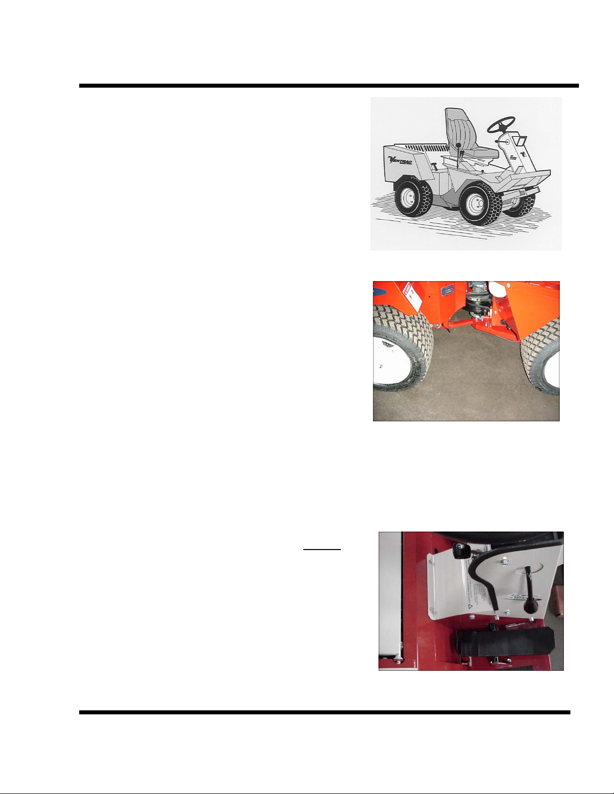
The first sight of the VENTRAC 3000 reveals its low
profile, four (4) identical drive tires and the
articulated frame. Less obvious is the easy-to-use
fast hitch and PTO drive that accommodates use of
other attachments.
SECTION C
OPERATION
The open left fender area enhances getting on and off
the VENTRAC 3000 (Figure 1). Extend the right
foot into place like getting into a car or pick-up, then
simply sit on the seat and lift the left foot into place.
To dismount, reverse the process.
Always put the Control Selector (Figure 2) DOWN
in PARK BRAKE position before leaving the seat.
This assures the neutral locking of the directional
control and the park brake engagement.
Figure 1
Figure 2
VPI VENTRAC 3000 C-1

SECTION C
OPERATION
FRONT CONTROLS
Many of the controls are located directly in front of
the operator on the dash and steering column.
(Figures 3, 4 & 5). Decals reveal their position,
function and motion.
Figure 4
Figure 3
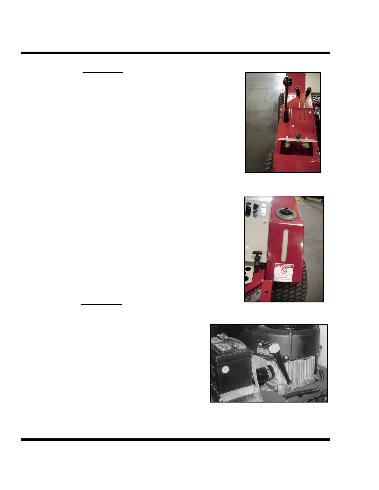
The right side of the dash has IMPORTANT
operational and safety instructions for the three-(3)
position Control Selector (Figure6).
1. DOWN – activates the park and
emergency brake. ALWAYS return lever to this
position when the tractor is not in use. The lever
must be in this position to START the engine.
2. LEVEL – causes the directional control
lever beside the operator to have a spring-assist-to-
neutral action. This position makes neutral easy to
find and maintain. If the tractor creeps when in
neutral, see “Neutral Adjustment” section.
3. UP – puts the directional control lever
beside the operator into an “Easy Shift” mode. This
position is recommended only for open area
operation where travel speed and direction is
relatively constant and control is very easy to
maintain. “Easy Shift” reduces operator arm fatigue
when machine is operated for an extended length of
time.
Figure 5
Figure 6
C-2 VENTRAC 3000 VPI

SIDE CONTROLS
Right side directional and front hitch lift control
(Figure 7) is standard on all VENTRAC 3000s. The
primary lever with the large round knob is the
directional control (sometimes called the Forward/
Reverse lever, or F/R).
I.) Once in the seat and the park brake released, the
lever can be moved. Forward movement from the
neutral position will cause the tractor to move
forward. The farther the lever is moved, the faster the
machine will travel. Returning toward the neutral
position will slow the machine and in neutral it will
stop. Note that the directional lever operates the
same for reverse and works equally well for starting
and STOPPING! This shift-on-the-go feature with
engine power and brake power to all four tires makes
the VENTRAC 3000 an amazing performer. Yet
extreme caution is critical to avoid unexpected and
difficult situations that could cause serious injury or
damage to operator or equipment. (See safety
section)
SECTION C
OPERATION
Figure 7
II.) Next to the directional control is the hydraulic
control lever for the front hitch (Figure 8). Pulling
the lever back raises the hitch. Moving it forward
lowers the hitch. Continuing forward puts the front
hitch in the FLOAT
position. Always use the float
position for mowing and other tasks where
flotation of the attachments is desired or
necessary.
Figure 8
Next to the hitch control lever is an optional lever
(Figure 8) that controls the auxiliary hydraulic
circuit. This lever activates attachments with
functions that have hydraulic hoses to the front quick
couplers.
VPI VENTRAC 3000 C-3
SECTION C
OPERATION
FENDERS
The right front fender has a small covered toolbox. It
also houses the optional auxiliary quick couplers
(Figure 9).
The left rear fender houses the 4 gallon fuel tank.
Always note the type of fuel: Unleaded gasoline or
Diesel. If decal is missing or unreadable, contact
your dealer or the factory for a replacement decal.
Determine fuel type before filling. Never over fill!
Stop before fuel spills over the fill tube.
A long slot in the left fender visible from the
operator’s seat serves as a fuel gauge (Figure 10).
Always keep sufficient fuel in the tank to prevent an
unexpected engine shut-off. When operating on
slopes, fuel level should be kept above the 1/4 mark.
Figure 9
BATTERY
Figure 10
The battery is located under the right rear fender
(Figure 11). Tilting the engine cover gives full
access to the battery. Before using jumper cables
or connecting a battery charger, always check
polarity. The RED cover means POSITIVE. The
BLACK cover means NEGATIVE. The negative
wire should always be connected to the frame!
Figure 11
C-4 VENTRAC 3000 VPI

SEAT
Each VENTRAC 3000 has an adjustable seat — fore
and aft. Each operator should adjust the seat for the
greatest control and comfort. (Figure 12). Note: Seat
plate mounting hole options are available for
additional variables in seat positioning. The seat can
be tilted forward during nonuse for inspection and
servicing access. To tilt the seat forward, press down
on the back of the seat with one hand and push down
the front of the seat locking bracket with the other.
A prop bracket is attached to the seat plate to prop
the seat in the tilted position. The seat and seat plate
can be removed by disconnecting the two seat switch
wires, removing the cotter pin on the right, tilting the
seat to the steering wheel, and moving it slightly to
the left. (Figure 13)
SECTION C
OPERATION
Figure 12
Figure 13
OWNER’S MANUAL
Owner’s manual is located in tube under the right
rear fender directly behind the battery. Release hood
latches, tilt hood and remove top tube cover to access
manual (Figure 14).
Figure 14
VPI VENTRAC 3000 C-5

SECTION C
OPERATION
FRONT HITCH & PTO DRIVE
The two rail, EASY-TACH, front hitch (Figure 15)
creates a stable and secure mounting of attachments
to the VENTRAC 3000! Just align the two rails to
the two corresponding receiver arms on the
attachment. Lower the tractor hitch for the initial
contact with the attachment arm tabs. Lift the
machine hitch to an in-line relationship and complete
the engagement. The EASY-TACH spring loaded
LOCKS secure the attachments. Always confirm that
the lock action has been completed.
Note: Engagement of attachment can be assisted by
opening the spring loaded “locks” by moving the
EASY-TACH lever (Figure 16) to the left side of the
hitch. Moving the lever to the right can assist the
closing action of the locks when necessary.
PTO DRIVEN ATTACHMENTS
After the EASY-TACH lever has been “locked,”
with engine stopped, put the PTO belt on the lower
groove of the PTO idler pulley (Figure 16) and
engage the tension lever on the attachment (Figure
17).
Figure 15
Figure 16
Figure 17
C-6 VENTRAC 3000 VPI

A TT ACHING A TT ACHMENTS
Most front mounted attachments can be positioned so
that it is convenient to drive into the hitch harness
with nearly correct alignment (Figure 19). Some
adjustment is usually required to complete the hitch
engagement.
When completely engaged, move the “Easy Tach”
lever to “lock” position (Figure 20). If lever will not
move into “lock” position, check the attachment for
complete engagement.
MOWER A TT ACHMENTS
Mower attachments have a floating hitch. If mower
cutting height is set near the highest position, the
machine can be driven to the hitch arm. Then raise
the hitch until the mating arms are parallel.
1. Shut off the engine and engage the park brake.
2. Walk to the front of the mower and push it into the
machine as far as the hitch will allow. Make sure
both sides are completely engaged and locked.
(Figure 21).
3. Install the mower PTO belt on the drive pulley
between the hitch arms (Figure 20).
Note:
1. Attachment change is made easier and safer by
always using level clean surfaces.
2. Heavy duty, close tolerance latch hooks (Figure
21) make complete engagement of attachment hitch
necessary on both sides before “Easy Tach” lock can
close.
SECTION C
OPERATION
Figure 19
Lock
Figure 20
Figure 21
VPI VENTRAC 3000 C-7

SECTION C
OPERATION
DETACHMENT
Attachments are detached by reverse sequence of
the attaching steps.
Note: EASY-TACH lever between the hitch arms
must be moved to the left side of the machine to
release the attachment. (Figure 23)
Note for mower hook up— If mower arms are too
low for the initial engagement, lift the mower
cutting height to a high position. This will position
the hitch arms high enough for drive-in contact.
PTO ENGAGEMENT
Move
Figure 23
When engaging power to front attachments, it is
necessary for the operator to be seated in the seat.
Increase the engine speed to at least 2500 RPM’s.
(See RPM indicator on the dash). Check that all is
clear before engaging the PTO switch (Figure 24).
When the PTO switch is engaged, an operation light
will come on. When the engine is cold, stalling is
possible at the moment of engagement. Increase the
engine RPM’s and/or increase the warm-up time and
try again. The VENTRAC 3000 is equipped with a
heavy-duty electric clutch causing potential engine
stalls by the abrupt and forceful transfer of power.
An integral brake system stops the PTO within 7
seconds when the switch is moved to OFF or the seat
switch is deactivated.
Figure 24
C-8 VENTRAC 3000 VPI

LIGHTS
(Figures 25 & 26)
Head and taillights improve safety and operational
visibility. Their use is highly recommended
especially at dawn or dusk and at night. The
headlight can be adjusted to the operator’s preference
by loosening, the mounting bolt directly under the
light fixture. The fixture can be moved so that the
light beam moves up or down, right or left. Once in
the desired position, retighten the mounting bolt.
STARTING PROCEDURE
1. Check engine oil, water, and fuel levels.
2. Read and understand operational and safety
instructions.
3. Make sure the right side, three (3) position control
selector is in start position (DOWN).
4. Move throttle forward about 1/4 stroke. (Engines
vary)
5. For gasoline models, pull the choke out. For diesel
models, turn the key counter-clockwise and hold
until the glow light goes off.
6. Turn the key clockwise until the engine starts. If
the engine fails to start in 15 seconds, stop. Check if
there is fuel in the tank. Make several more attempts
to start. If the engine does not start, contact a
mechanic or the dealer.
7. Once the engine is started, let it warm up. Always
check to see if the steering system is responsive
before attempting to drive. In cold weather
conditions, extend the warm-up period.
8. For the PTO to operate, the operator has to be
sitting on the seat.
SECTION C
OPERATION
Figures 25 & 26
VPI VENTRAC 3000 C-9

SECTION C
OPERATION
OPERATING ON SLOPES
Operation on slopes decreases machine stability and
increases the possibility for unexpected difficulties.
Only experienced VENTRAC 3000 operators should
operate the machine on slopes and extra caution
should be applied that include: (See drawings at
right.)
1.— avoiding uneven, loose or wet terrain.
2.— staying clear of drop-offs, holes, ditches,
rocks, or objects that could cause a sudden and/or
unexpected force on the machine.
3.—using sufficient engine rpms to prevent
engine stall.
4.—using sufficient fuel in tank to assure
continuous operation.
5.—making slow and cautious starts, stops,
and turns.
6.—limiting maximum operation to 20/25
degrees respectively.
7.—ceasing operation if machine instability
is suspected or evident, or if the operator is
uncomfortable or unsure of continuing safely.
8.—using an attachment as much as possible.
Mounted attachments increase the overall length and
can add stability to the machine.
9.—reducing the degrees of turns and/or
turning down hill as much as possible.
10.—using roll cage and seat belt
11.—Do not operate carelessly!
.
x
a
m
s
e
e
r
g
e
d
0
2
.
x
a
m
s
e
e
r
g
e
d
5
2
Turning reduces vehicle stability!
Keep engine oil level near full mark
when operating on slopes.
The ultimate responsibility for safe
operation on slopes is the
responsibility of the operator!
IF IN DOUBT...DON’T!!
C-10 VENTRAC 3000 VPI

SECTION D
SERVICE & MAINTENANCE
SERVICE & MAINTENANCE
ENGINE
See engine manufacturer’s OWNERS MANUAL in
your VENTRAC 3000 manual pocket for details on
engine care.
GENERAL INSTRUCTIONS
Daily:
Check oil level daily
Check/clean air intake screen
8 Hours:
initial oil change
25 Hours:
Clean air intake foam element
100 Hours:
Change oil and oil filter
Clean air cleaner paper element
300 Hours:
Replace air cleaner paper element
Service intervals indicated are to be used as a guide.
Service should be performed more frequently in
severe operating conditions.
For engine problems, see “Trouble Shooting” guide
in engine manual.
VPI VENTRAC 3000 D-1
SECTION D
SERVICE & MAINTENANCE
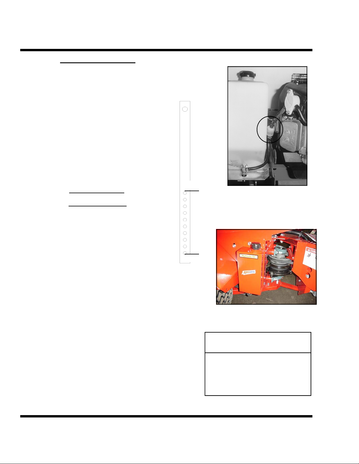
FUEL LINE FILTER
IN-LINE FILTER
All VENTRAC 3000’s have an in-line fuel filter
(Figure 1) located next to the fuel tank.
Always use clean, fresh fuel. Keep the fill area clean
and the fuel cap in place except for filling. If or when
any of the above conditions are not met or the engine
lacks power, especially under load, the fuel filter
should be checked. If the in-line filter needs to be
replaced, be sure to install the new one with the flow
arrow pointing toward the engine.
TRANSAXLES
HYDRAULIC OIL
Rear transaxle is prefilled. Oil level should allow for
expansion from heat without over-flowing through
the vented cap on top of case. This oil level will
remain constant unless leakage occurs. Oil level
when cold to be 1-1/2” (4 cm) from top of the
transaxle housing. Note: side plug can be used to fill
and determine “full” on rear transaxle.
Front transaxle has an oil tank, vented cap, and
dipstick (Figure 2). Never fill oil above high level
on dipstick. Heat expansion could cause unwanted
over flow.
Additional oil may be required when new
attachments are connected to the auxiliary circuit
(optional). The attachment components are shipped
without oil. Additional oil is needed only after the
initial hook up.
HIGH
Figure 1
OPERATING
RANGE
LOW
Figure 2
REQUIRED OIL
SPECIFICATION
A M S O I L
Synthetic
Hydraulic Transmission Oil
TYPE ATH SAE 30
D-2 VENTRAC 3000 VPI

Hydrostatic Oil (Cont.)
Note: Activate attachment hydraulics full stroke in
both directions several times to purge the system of
air before replenishing oil in front transaxle
reservoir.
Hydraulic filter located behind the front right fender
(Figure 3) does not
need to be changed unless
serious or unusual contamination occurs to the
system. Contact dealer for further direction.
Note: Generally the hydrostatic oil level remains
constant except when:
1) New attachments are added that use the
auxiliary oil circuit. (front transaxle only)
2) There is an oil leak.
NOTE: Replacement of hydrostatic oil is
not recommended except in the
event of contamination.
SECTION D
SERVICE & MAINTENANCE
Figure 3
Transaxle capacity:
Approximately 1 gallon
BATTERY
Battery group—22 NF
When it is necessary to remove and/or replace the
battery, remove both cables. Then remove the front
or rear hold-down bracket (Figure 4). To install the
new battery, reverse the above instructions. Be sure
the new battery has the same dimensions, top
terminals, and is installed with the terminals on the
side toward the engine.
Figure 4
VPI VENTRAC 3000 D-3

SECTION D
SERVICE & MAINTENANCE
BRAKE ADJUSTMENT
A disk brake is activated when the control selector
on the right side of the steering column is moved
down into park position.
To adjust brake tension, use a 7/16 wrench on the
linkage at the brake on the left side of the front
transaxle (Figure 5). If the adjustment is too tight,
the control selector will be difficult to move to park
position. Brake adjustment should rarely be needed
because transaxles are automatically locked into
neutral when brake is engaged.
NEUTRAL ADJUSTMENT
Figure 5
The machine should always come to a complete stop
when the Control Selector is in the “park brake”
position (down) or in the “spring assist to neutral”
position (level) when the Directional Control lever is
released (Figure 6). If the machine consistently
wants to creep while in neutral, an adjustment must
be made.
Each transaxle has its own “neutral locator.” The
factory setting generally will not require adjustment.
The most likely adjustment needed is in the cable
connecting the two transaxle control mechanisms.
Simply lengthen or shorten one end of the cable
where it’s mounted to the frame
bracket (Figure 7 &
8). The connecting cable should allow each transaxle
mechanism to settle into its own neutral position.
Secure cable ends when that position is attained.
Note: Engine needs to be running to make the
neutral adjustment. Jacking one tire up on each
transaxle will prevent accidental movement and
possible injury. If uncertain or in doubt about this
procedure, contact your servicing dealer.
Figure 6
Figure 7-front
Figure 8-rear
D-4 VENTRAC 3000 VPI

TOWING/FREE-WHEELING
Each transaxle is equipped with leverage to release
hydrostatic pumps for slow, level, short distance
towing. Both are located in the center pivot area of
the tractor. See (Figure 9 and 10). Each handle
needs to be pulled out a short distance and must be
secured in notch. Always release BOTH handles
when towing is complete! Failure to release one or
both handles creates a potential free-wheeling
hazard. Park brake is still operative in free-wheeling
mode but must be released in order to tow.
SECTION D
SERVICE & MAINTENANCE
Figure 9—Right side
Front frame
Figure 10—Left side
Rear frame
VPI VENTRAC 3000 D-5
SECTION D
SERVICE & MAINTENANCE
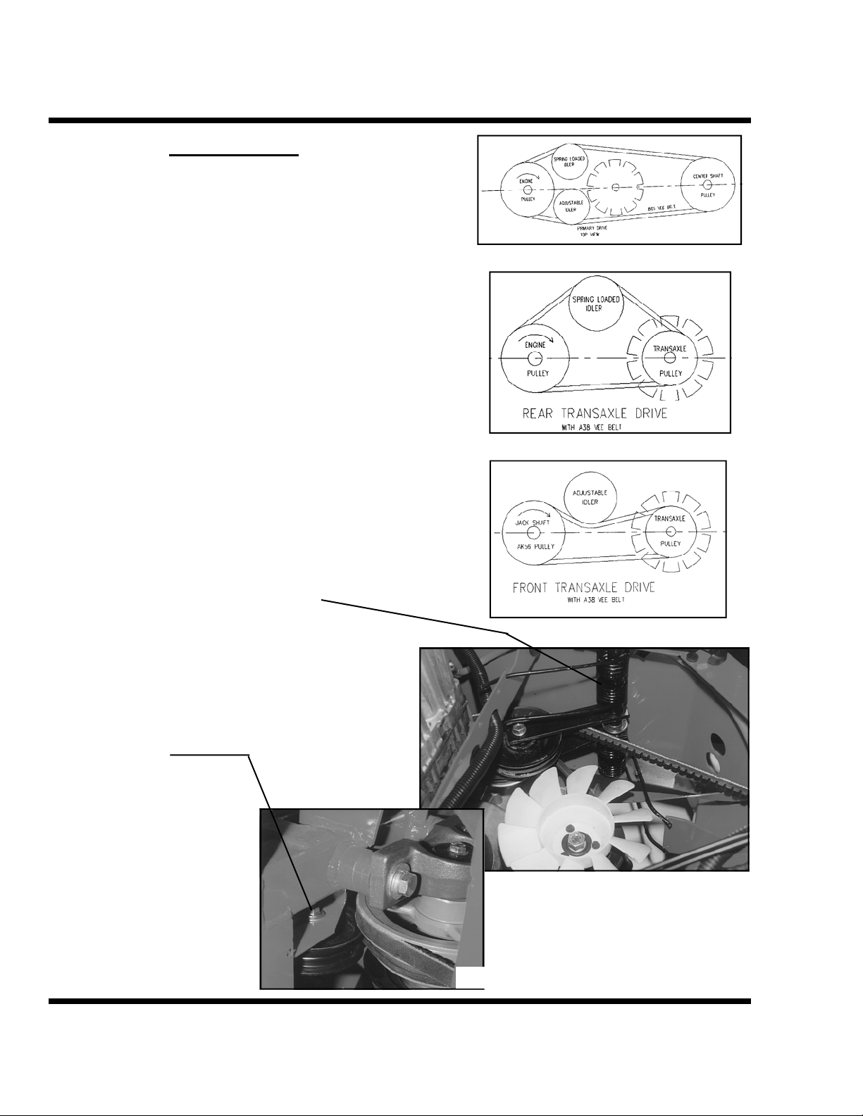
DRIVE BELTS
The VENTRAC 3000 has three drive belts: one
PRIMARY drive belt, one REAR transaxle belt and one
FRONT transaxle belt.
The PRIMARY DRIVE BELT (Figure LTB-A) connects
the engine pulley to the center drive shaft pulley in the
pivot area of the articulated frame. It is the top belt in the
drive system. It has two vee belt idlers. One fixed idler
just below the right front corner of the engine and other
spring-loaded idler on the opposite side.
The REAR TRANSAXLE BELT (Figure LTB-B) is the
lower belt. It connects the lower engine pulley to the rear
transaxle pulley with the plastic-cooling fan. It has one
vee belt idler located just below the primary drive belt
spring loaded idler.
The spring-loaded idlers have a unique torsion spring
tension system. The spring is mounted on the axis of the
leverage and has two extended prongs. The prongs can be
engaged individually making the tensioning process
manageable by hand. This leverage for the two rear drive
belts is located on the same axis (Figure 11).
The FRONT TRANSAXLE BELT (Figure LTB-C) is
located on the front chassis frame. It is on the same plain
as the rear transaxle belt. It goes from the center drive
shaft pulley to the front transaxle pulley with the plasticcooling fan. This belt has a fixed flat belt idler located
just below the crossover frame in the center pivot area of
the chassis. Figure 12).
All idlers should maintain proper alignment with the
belts. Mounting points should always position the idlers
in the same horizontal plain as the drive and driven
pulleys. Any angular positioning
will compromise the life of the
belt. Due to the vibration nature
of spring loaded idlers the bolts
securing them should be check
periodically to assure tightness.
Figure LTB-A
Figure LTB-B
Figure LTB-C
Figure 11
Figure 12
D-6 VENTRAC 3000 VPI

BELT REPLACEMENT
Remove cover plate over the rear chassis to access fan
and belt area (Figure 13) and center pulley cover on rear
frame. Release both spring prongs on each of the two- (2)
spring loaded idlers. The two springs are on the inside of
the rear frame on the left side. Remove belts from idler
engagement. Also disconnect shift cable from the
transaxle lever.
1) Rear Transaxle Belt
To replace the rear transaxle belt, access it from the rear –
under the engine. Dislodge it from the engine pulley
(Figure 14). Push or pull it up between the transaxle and
the engine. Remove it from around the cooling fan pulley.
Replace the new belt by reversing these steps and tension
the idler.
2) Primary Drive Belt
To change the Primary Drive Belt access it from the rear under the engine. First remove the rear transaxle belt from
the engine pulley and let it lay down on the transaxle case
out of the way. Dislodge the primary belt from the engine
pulley and move it up between the engine and the
transaxle.
Second remove the two ½” bolts and the two spacers from
the top center shaft pillow block bearing (Figure 15).
This makes clearance for belts to be removed or installed
over the center shaft assembly. Do not
from shaft.
Third dislodge the front part of the belt from the center
shaft pulley and move it up through the pillow block
spacer clearance. Install the new belt with these same
steps in reverse order and tension the idler.
3) Front transaxle Belt
First remove the two ½” bolts and the two spacers from
the top center shaft pillow block bearing (Figure 15).
This makes clearance for belts to be removed or installed
over the center shaft assembly. Do not
from shaft.
Remove the adjustable flat belt idler on the front transaxle
belt located just below the crossover frame section
(Figure 16).
remove bearing
remove bearing
SECTION D
SERVICE & MAINTENANCE
Figure 13
Figure 14
Figure 15
Figure 16
VPI VENTRAC 3000 D-7

SECTION D
SERVICE & MAINTENANCE
Move the primary drive belt off the center shaft pulley
and let it lay in the open shaft area just above the pulley
(Figure 17).
Take the belt off of the transaxle pulley and cooling fan.
It may be necessary to rotate the fan to assist the belt removal. Fin can tolerate considerable deflection (Figure
18).
Pull the front transaxle belt into the center shaft area. Slip
it through the loop of the primary drive belt and out over
the top bearing assembly.
Reverse this procedure to install the new belt.
* * * * *
PTO DRIVE BELT
The PTO Drive Belt is the bottom belt on the center shaft
pulley assembly. It is directed around the front transaxle
to the double pulley located on the lift hitch (Figure 19).
A torsion, double prong spring activates the PTO idler. It
is accessed on the outside of the front frame down behind
the right front tire (Figure 20).
Figure 17
Figure 18
Figure 20
Figure 19
D-8 VENTRAC 3000 VPI
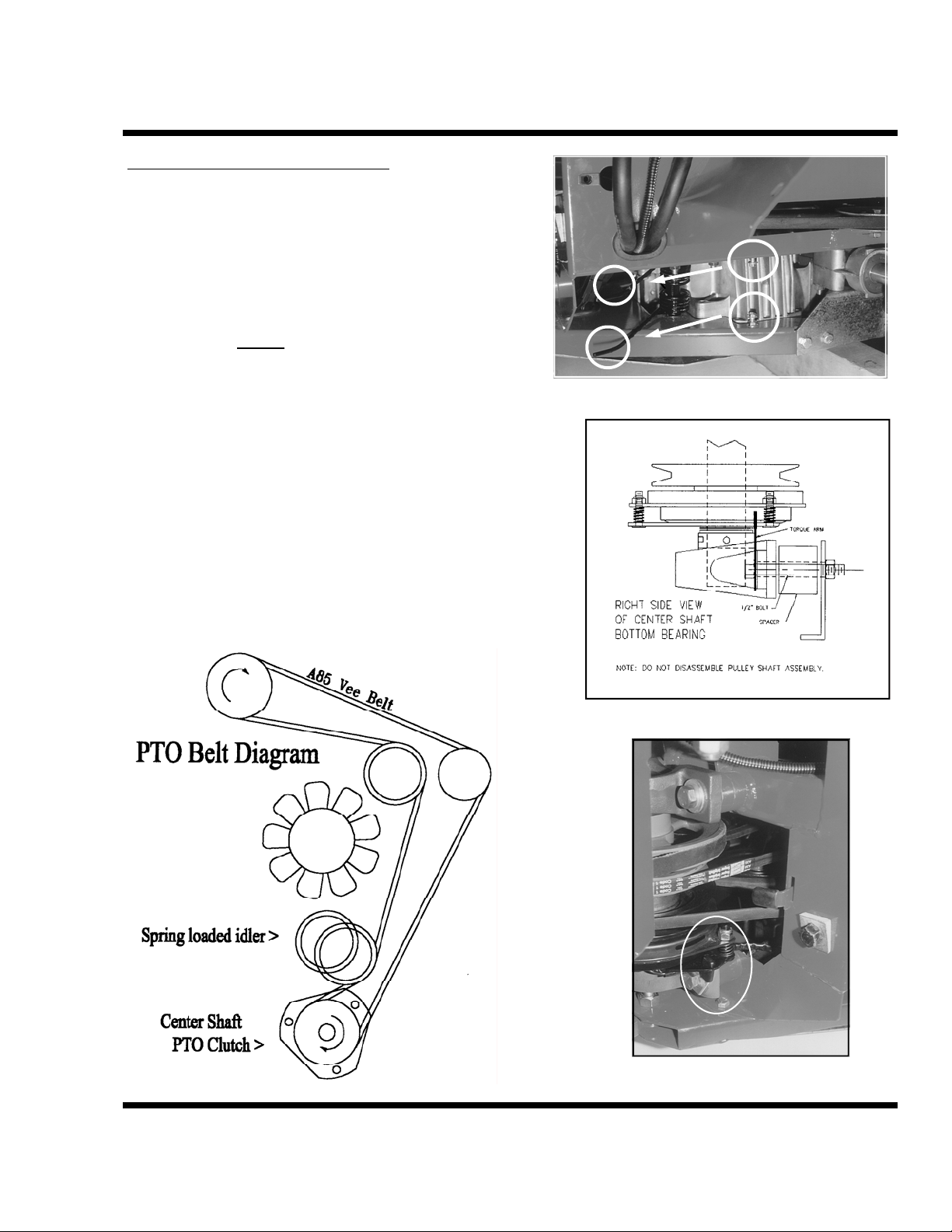
PTO BELT REPLACEMENT
Release the idler spring prongs on the lower, right side
(outside) of the front frame (Figure 21).
Remove the two ½” bolts from the bottom center-shaft
pillow-block bearing, the two spacers and the clutch
torque arm (Figure 22 & 23). This gives clearance to
remove or install belt over the lower end of the centershaft assembly. Do not
Dislodge belt from the front pulleys and lower it over the
clutch assembly and through the bearing mount spacer
area.
Reverse procedure to install the new belt. Be sure to
reinstall clutch torque arm (Figure 22 & 23).
Note: Remove seat assembly and any front mounted
attachment for greater access. See seat section (page C-5).
remove bearing from shaft.
SECTION D
SERVICE & MAINTENANCE
Figure 21
Figure 22
Figure 23
VPI VENTRAC 3000 D-9

SECTION E
SERVICE SCHEDULE
Service Schedule
The operator’s manual and decals should be read and understood before operating the machine or
attachments. This manual should be reviewed periodically or when in doubt about any function,
procedure, or safety factor on this equipment.
Daily
Check the oil and water levels (liquid cooled engines only) daily in the engine. Fuel level needs to be
checked every couple hours. When working on slopes, keep a minimum of 1/4 tank of fuel. Flywheel
or radiator screen and air intake filter should be checked frequently when working in a dirty
environment. Clean or change as needed. Keep equipment clean. Accumulated debris can restrict
performance, cause equipment failure and be a safety hazard.
Visual
Many equipment conditions are visible before operation. For example, an oil leak, low tire inflation,
obstructed flywheel screen, loose or missing hardware, shields or a broken belt. These should be
repaired or replaced before operation!
Some equipment conditions are not evident until operation. For example, a failing bearing, broken
electrical wire, faulty switch or loose part. These should be corrected as soon as evident. Operation
should cease immediately if an unsafe condition is observed!
Operators should always be alert for potential problems. Personal safety and the safety of others as
well as the performance of the equipment depend on the operator’s care and repair of the machine and
continuous caution and control of the same.
Engine Oil and Filter Change
Kawasaki — Initial change at 8 hours and every 100 hours thereafter.
Note: refer to engine manual for further details.
Transaxle Oil and Filters
Change oil and oil filter only if the system has been contaminated. Check oil levels every 100 hours.
If there is an oil leak or new attachments have been used that require “priming”, the front transaxle oil
level should be checked at that time.
Storage
Drain fuel tank, check for proper tire inflation and remove battery.
E-1 VENTRAC 3000 VPI

SECTION F
ELECTRICAL DIAGRAM
ELECTRICAL DIAGRAM
19 HP KAWASAKI ENGINE
HBA1346-HBA1425
21 HP KAWASAKI ENGINE
Beginning with Serial Number: JBA1426
Revised 10-29-02
VPI VENTRAC 3000 F-1

LIMITED WARRANTY – VENTRAC TURF EQUIPMENT
Venture Products, Inc. (shall be referred to as V.P.I.) warrants on the terms and conditions herein, that it
will repair, replace, or adjust any part manufactured by Venture Products Inc. and found by Venture
Products Inc to be defective in material and / or workmanship.
Effective September 1
generator) for Residential use only is limited to Three (3) years from original purchase date. Ventrac
Tractors & Attachments used Commercially or for any income producing purpose is limited to Two (2)
years from original purchase date. Ventrac ET200 turbine blower (turbine only) is limited to Two (2) years
from original purchase date. Ventrac HG100/HG150 generator is limited to One (1) year
purchase date. Ventrac Tractors & Attachments used for Rental
purchase date. (NOTE: All accessories such as: 3-point hitch, foot pedal, dual wheel kit, etc. will be
covered under the above warranty periods as they would apply provided they are installed by an Authorized
Ventrac Dealer.) This warranty may be transferred and will carry the remainder of the warranty starting
from the Original Purchase/Registration date with the dealership and/or V.P.I. In the event that product/s
originally registered as (3) year Residential use
would change to the remainder of (2) year Commercial use
Purchase/Registration date with the dealership and/or V.P.I.
If this warranty covers a consumer product as defined by the Magnusson-Moss warranty act, no warranties,
express or implied, (including, but not limited to, the warranty of merchantability or fitness for a particular
purpose) shall extend beyond the applicable time period stated in bold face type above.
If this warranty covers a product used commercially or for any income producing purpose, the foregoing
warranties are in lieu of all other warranties and no representations, guarantees or warranties, express or
implied, (including, but not limited to, a warranty of merchantability or fitness for a particular pu rpose), are
made by V.P.I. in connection with the manufacture or sale of its products.
The engine warranty is covered by its respective engine manufacturer. Please refer to the engine
manufacturer’s warranty statement that is included in the owner’s manual.
The Ventrac turf equipment, including any defective parts, must be returned to an Authorized Ventrac
Dealer within the warranty period. The warranty shall extend to the cost to repair or replace (as determined
by V.P.I.) the defective part. The expense of pickup and delivery of equipment, service call drive time
or any transportation expense incurred for warranty repair is the sole responsibility of the owner
and is not covered under warranty by Ventrac and/or V.P.I. V.P.I.’s responsibility in respect to claims
is limited to making the required repairs or replacements, and no claim of breach of warranty shall be cause
for cancellation or rescission of the contract of sale of any Ventrac equipment. Proof of purchase may be
required by the dealer to substantiate any warranty claim. Only warranty work performed and submitted by
an Authorized Ventrac Dealer may be eligible for warranty credit.
This warranty extends only to Ventrac turf equipment operated under normal conditions and properly
serviced and maintained. The warranty expressly does NOT cover: (a) any defects, damage or
deterioration due to normal use, wear and tear, or exposure; (b) normal maintenance services, such as
cleaning, lubrication, oil change; (c) replacement of service items, such as oil, lubricants, spark plugs, belts,
rubber hoses or other items subject to normal service replacement; (d) damage or defects arising out of, or
relating to abuse, misuse, neglect, alteration, negligence or accident; (e) repair or replacement arising from
st
2005, Ventrac warranty on Tractors & Attachments (excluding the HG100/HG150
from original
is limited to 180 days from original
are to be transferred to a commercial user the warranty
starting from the Original
9 - 2

LIMITED WARRANTY – VENTRAC TURF EQUIPMENT
operation of, or use of the turf equipment which is not in accordance with operating instructions
as specified in the operator’s manual or other operational instructions provided by V.P.I.; (f)
repair or
or modified so as to, in the determination of V.P.I., adversely affect the operation, performance or
durability of the equipment or that has altered, modified or affected the turf equipment so as to change the
intended use of the product; (g) repair or replacement necessitated by the use of parts, accessories or
supplies, including gasoline, oil or lubricants, incompatible with the turf equipment or other than as
recommended in the operator’s manual or other operational instructions provided by V.P.I.; (h) repairs or
replacements resulting from parts or accessories which have adversely affected the operation, performance
or durability of the turf equipment; or (i) damage or defects due to or arising ou t of repair of Ventrac turf
equipment by person or persons other than an authorized Ventrac service dealer or the installation of parts
other than genuine Ventrac parts or Ventrac recommended parts.
The sole liability of V.P.I. with respect to this warranty shall be repair and replacement as set forth herein.
V.P.I. shall have no liability for any other cost, loss, or damage. In particular V.P.I shall have no liability or
responsibility for: (i) expenses relating to gasoline, oil, lubricants; (ii) loss, cost or expense relating to
transportation or delivery of turf equipment from the location of owner or location where used by owner to
or from any Authorized Ventrac Dealer; (iii) travel time, overtime, after hours time or other extraordinary
repair charges or charge relating to repairs or replacements outside of normal business hours at the place of
business of an Authorized Ventrac Dealer; (iv) rental of like or similar replacement equipment during the
period of any warranty repair or replacement work; (v) any telephone or telegram charges; (vi) loss or
damage to person or property other than that covered by the terms of this warranty; (vii) any claims for lost
revenue, lost profit or additional cost or expense incurred as a result o f a claim of breach of warranty; or
(viii) attorney’s fees.
The remedies of buyer set forth herein are exclusive and are in lieu of all other remedies. The liability of
V.P.I., whether in contract, tort, under any warranty, or otherwise, shall not extend beyond its obligation as
set forth herein. V.P.I. shall not be liable for cost of removal or installation nor shall V.P.I. be responsible
for any direct, indirect, special or consequential damages of any nature. In no event shall V.P.I. be liable
for any sum in excess of the price received for the goods for which liability is claimed.
There are no representations or warranties which have been authorized to the buyer of the turf equipment
other than set forth in this warranty. Any and all statements or representations made by any seller of this
equipment, including those set forth in any sales literature or made orally by any sales representative, are
superceded by the terms of this warranty. Any affirmation of fact or promise made by V.P.I. or any of its
representatives to the buyer which relates to the goods that are the subject to this warranty shall no t be
regarded as part of the basis of the bargain and shall not be deemed to create any express warranty that such
goods shall conform to the affirmation or promise.
No employee, distributor, or representative is authorized to ch ange the foregoing warranties in any way or
grant any other warranty on behalf of V.P.I.
Some states do not allow limitations on how long an implied warranty lasts or allow the exclusion on
limitation of incidental or consequential damages, so the above limitation or exclusion may not apply to
you.
This warranty gives you specific legal rights, and you may also have other rights which vary from state to
state.
This warranty applies to all Ventrac turf equipment sold in the United States and Canada.
replacement arising as a result of any operation from Ventrac turf equipment that has been altered
9 - 3
 Loading...