

Page 1
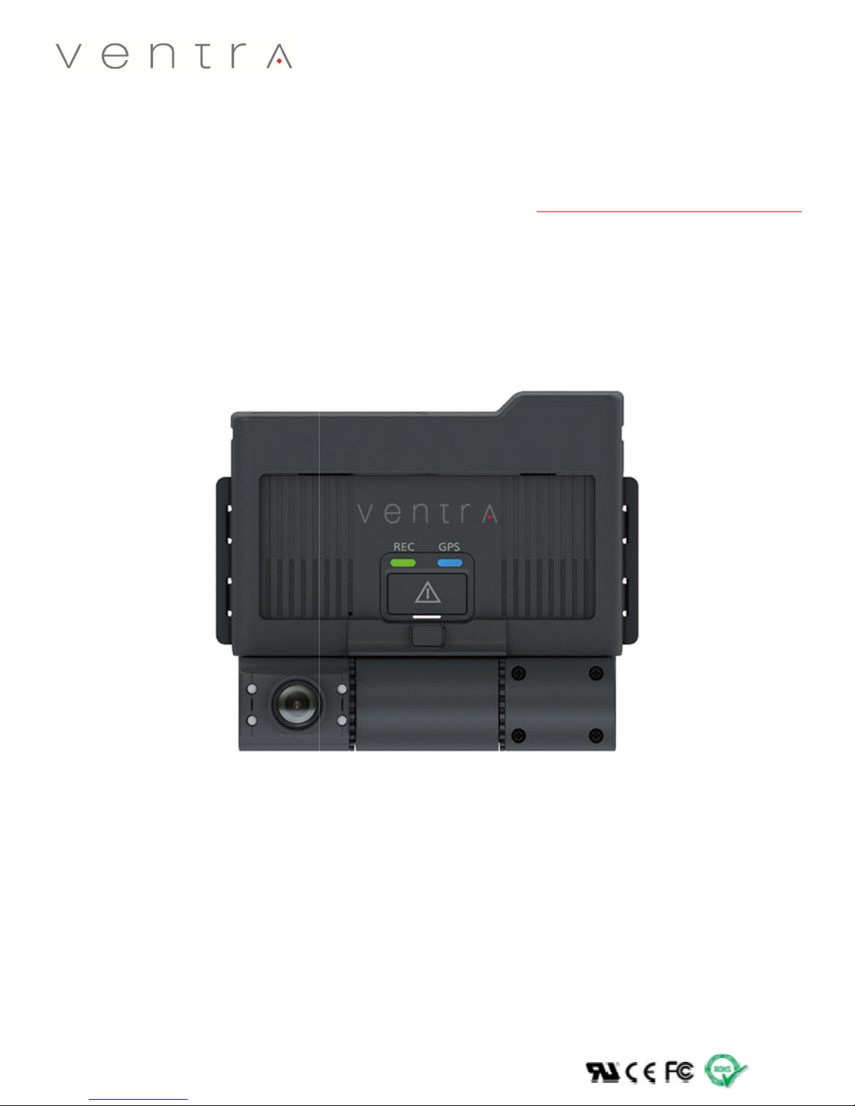
Vehicle Video
USER GUIDE
VDR-700
Recorder
Page 2

Table of Contents
1. UNDERSTANDING THE USER MANUAL ................................................................................................................5
1.1 S
AFETY WARNINGS
1.2 W
INDSHIELD MOUNTING DISCLAIMER, AUDIO RECORDING LEGAL DISCLAIMER
............................................................................................................................................................ 6
.............................................................................. 7
2. GETTING TO KNOW THE DRIVE RECORDER ..........................................................................................................8
2.1 S
YSTEM CONTENT
2.2 O
PTIONAL ACCESSORIES
2.3 S
YSTEM LAYOUT
............................................................................................................................................................. 8
..................................................................................................................................................... 9
.............................................................................................................................................................. 10
3. GETTING READY TO START RECORDING ............................................................................................................ 11
3.1 I
NSERT MEMORY CARD
3.2 R
EMOVE MEMORY CARD
3.3 S
ELECTING COMPATIBLE MEMORY CARD AND FILE FORMAT / FORMAT SD CARD
..................................................................................................................................................... 11
................................................................................................................................................... 11
........................................................................ 12
4. INSTALLATION ................................................................................................................................................. 13
4.1 P
LACEMENT AND INSTALLATION OF
4.2 V
EHICLE
FUSE
CONNECTION FOR PERMANENT POWER
4.3 A
DJUSTMENT CAMERA ANGLE
4.4 T
AMPER RESISTANT ENCLOSURE
VDR ........................................................................................................................ 13-16
.......................................................................................................... 17
............................................................................................................................................ 18
.................................................................................................................................... 19-20
5. RECORDING ..................................................................................................................................................... 21
5.1 V
IDEO RESOLUTION
5.2 O
VERLAY INFORMATION
5.3 M
EMORY CARD STORAGE / FILE ALLOCATION /PRIMARY AND SECONDARY MEMORY CARD
.......................................................................................................................................................... 21
.............................................................................................................................................. 21-24
.......................................................... 25
5.3.1 Directory of NORMAL recording file area ............................................................................................................ 26
5.3.2 Directory of EVENT video file area....................................................................................................................... 26
5.3.3 Directory of EMERGENCY video file area ............................................................................................................. 26
5.3.4 Directory of LOG area .......................................................................................................................................... 26
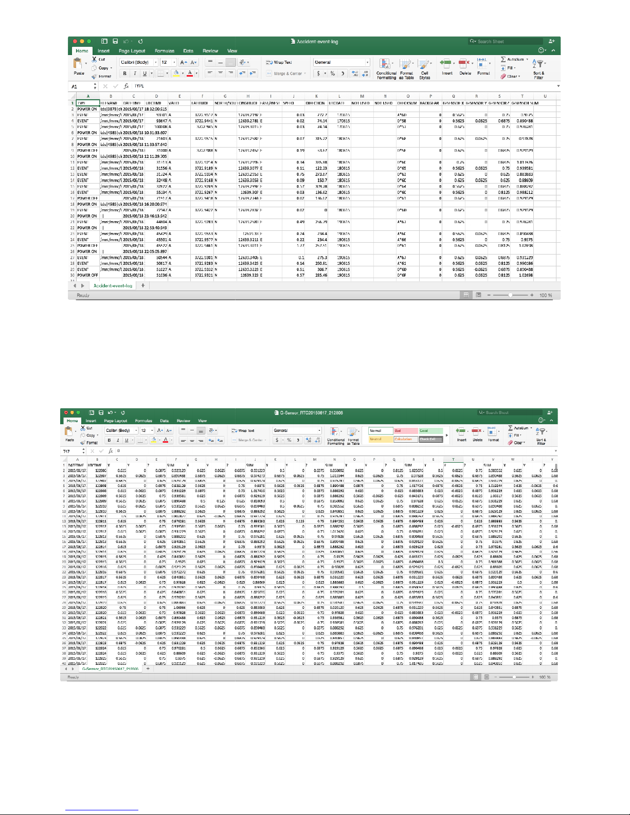
5.3.4 Accident, Event, GPS log report…………………………………………………………………………………………………………………27-28
6. RECORDING TIME / FRAME ................................................................................................................................... 29
7. LED SIGNAL ........................................................................................................................................................ 30
7.1 LEDS S
TATUS INDICATOR
.................................................................................................................................................. 30
8. VENTRA SOFTWARE PC REQUIREMENT ................................................................................................................. 31
8.1 S
YSTEM REQUIREMENT
8.2 I
NSTALL
VDR-700 S
8.3 U
NINSTALL PC MANAGER
.................................................................................................................................................... 31
OFTWARE
...................................................................................................................................... 32-34
............................................................................................................................................ 35-36
8.4 VDR-700 SOFTWARE OVERVIEW ......................................................................................................................... 37
8.4
SOFTWARE DASHBOARD LAYOUT / ICON EXPLANATION
8.4
PRINT EVENT REPORT
8.4 S
AVE / EXPORT IMAGE & VIDEOS
........................................................................................................................................................ 41
....................................................................................................................................... 42
.................................................................................................... 328-40
8.5 SETTING CONFIGURATION .................................................................................................................................. 43
8.5.1 Record setting ...................................................................................................................................................... 44
8.5.2 Event setting ........................................................................................................................................................ 45
8.5.3 Time setting ......................................................................................................................................................... 46
8.5.4 User setting ......................................................................................................................................................... 47
8.5.5 Storage setting .................................................................................................................................................... 48
8.5.6 Etc. (Voice Guidance, Video Out, Watermark, LED Status indicator) .................................................................. 49
9. SPECIFICATIONS ................................................................................................................................................... 50
10. WARRANTY ........................................................................................................................................................ 52
Page 3

Overview
The VDR-700 is an all-in-one commercially grade, High Definition Vehicle Video Recorder – Fleet Management
System. With an integrated video camera and passive GPS, the VDR records detailed information such as
video at a stunning 720P resolution, audio, speed, route history, vehicle/driver ID , date and time.
Designed for both forward facing and in-cabin recording, the VDR is an easy to install, rugged system ideal for
passenger, commercial, bus, law enforcement, trucks and specialized agriculture and construction vehicles –
across various industries.
Supporting up to 128GB capacity, the VDR-700 records all vital information on a solid-state storage technology
to ensure stability of data. Auto continuous loop recording enables the system to constantly record Normal
and Events. A built-in 3-Axis G-Sensor detects and records any sudden accelerations, braking or impact.
Recorded files can be viewed from our licenses free, user-friendly software by removing the SD card from the
unit and connecting it to a PC. From there, files can be easily accessed or searched via different criteria such
as date, incident and type of recording.
Features
- 3 Cameras Max (2 Built-in + 1 Optional)
- Sudden Acceleration / Braking Trigger
- 720P HD Resolution x 2 + D1 on optional
camera
- Up to 128GB max storage ( 64GB x 2 )
- Records Video, Audio, Speed, Route, Vehicle ID
- Recording - Auto Continuous / Event /
Emergency / Parking
- 15/Pre + 15/Post seconds Event Recording
- Back up video files and images
- Vandal Resistant bracket and screws
- Adjustable camera angles
- IR LED for in-cabin recording
- Assignable Vehicle, Driver and Company ID
- Set vehicle max speed limit trigger
- WiFi and 3G connection (Optional)
- Incident Reporting
- Analytics Vehicle History Report
- Built in Passive GPS for route history
- Built in Mic / Speaker
- GPS + G Sensor Log
- User and Password Security
- Video Out connection to LCD screen
- G Sensor sensitivity
- Microphone On / Off
- System Log in Excel format
- Video Mirror / Flip capability
- Back up camera function
- USB connection to external device
- UL-94 Flame retardant material
Page 4

VDR-700 various recording modes
Continuous / Event / Parking
Continuous
The VDR automatically record when the vehicle is on and power is supplied to the system. By
default, it records Audio, Video, Speed, G Force, Location, Coordinates, Time and Date in a
Continuous cycle, replacing the oldest normal event data files with the newest.
It takes approximately 30 seconds for the system to initialize upon the start of the vehicle. Both
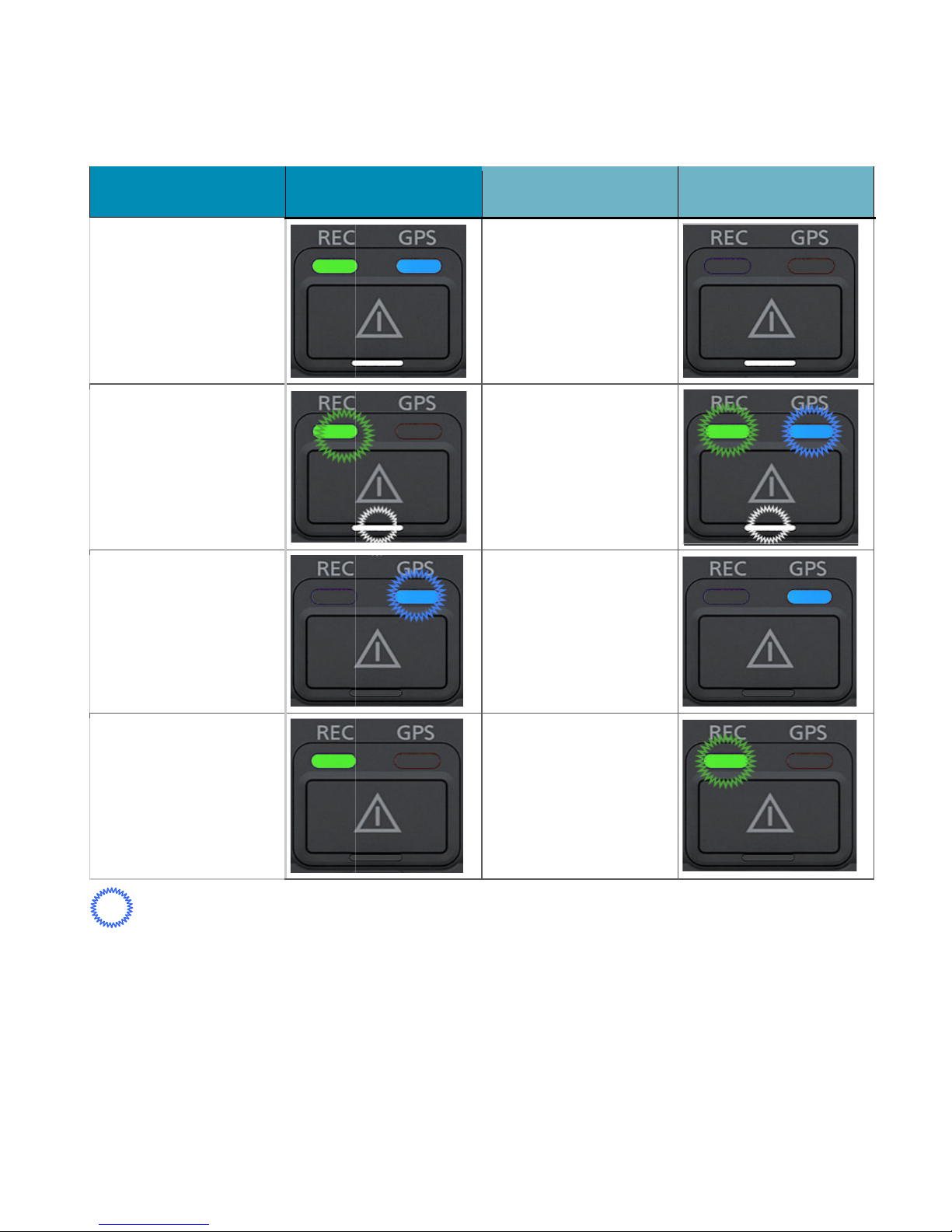
GPS and REC LED will illuminate and stay on, which indicates normal operation.
Note:
GPS signal and LED may require additional time to acquire signal depending on the location,
environment such as parking lot structures, trees, buildings…etc.
Event
Over Speed / Sudden Start / Sudden Brake / Parking
The VDR is equipped with a powerful algorithm that can detect various conditions, customizable
parameters and mark each specific events accordingly. These events can then be displayed in the Ventra
software software during playback to clearly identify Events
This provides valuable insight on the driving history and offers a comprehensive fleet management system.
In case of an incident, the Emergency button on the VDR can be pressed, or by using the optional
EX7-EFP External Foot Pedal to "Bookmark" the recording. The VDR is designed to continuously
record with or without the activation of the event button. The Emergency feature simply allows
the system to index the file as an Event, and prevents overwriting the file once the disk is full.
This feature can be useful if the driver witnesses an incident, an escalated situation, or gets into
an accident.
Parking
Parking mode recording is an innovative feature that enables the VDR-700 to record while the
vehicle is parked. The system automatically switches to parking mode after idling for a period of
time and intelligently switches to a standby status. Utilizing motion detection the system
automatically starts recording when movement is detected.
USER GUIDE V1.0.0
4
Page 5
USER GUIDE V1.0.0
1.
Understanding the
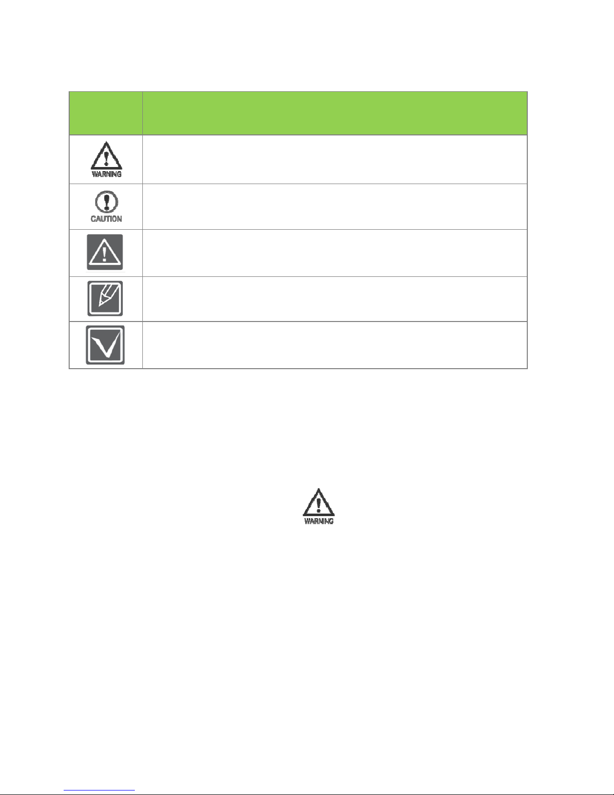
Failure to follow these safety warnings could potentially result in an accident,
collision resulting in serious injury or death.
explicitly and
in a manner that does not obstruct the driver’s view of the front or sides
of the vehicle, or interfere with the safety of operating the vehicle.
Do not operate, adjust or view this recorder while driving or when vehicle is in motion
insecurely
Please comply with all driving and traffic regulations
To reduce the risk of fire or electric shock, do not expose this unit to water, liquid, rain or
There is a potential risk of
There is a potential risk of personal injury or damage to the product.
To reduce the risk of fire, explosion, electric shock, or personal injury when
using your drive recorder, follow these basic safety precautions.
are hints or page number references you will find helpful when you
operate the drive recorder.
Settings required before using a function.
on the dashboard, or place the device in front of or
1.1 Safety Warnings
user manual
Safety Icon
Meaning
death or serious injury.
Here
Please follow all instructions
1.2 Safety items for use
Install the device
Do not place the device
above an airbag
moisture
keep for future reference
5
Page 6

USER GUIDE V1.0.0
Disconnect the power from the
Disconnect and replace the cable if wire is stripped or damaged
If using the permanent battery power cable to connect the
connect the power plug from the unit. Vehicle battery will be
drained if left unoperated for an extended period of time depending of the size
When exposed to direct sunlight for a period of time, the equipment may become hot.
Please exercise caution when touching the equipment
Do not disassemble or alter the equipment, cable or accessories as this may lead to
equipment error and failure
In the event of an impact or accident, please check to ensure the equipment is properly
ecured. Inspect the mounting bracket and adh
Fuse rating must be in rated capacity
When exposed to direct sunlight, the equipment may become hot. Please exercise caution
when touching the equipment
connected, do not remove the micro SD card as it may cause memory card
Do not touch SD card with oily or wet hand as it may cause product failure
Do not put foreign material into card insertion slot of the terminal, it may cause product
Do not modify the name of file folders in the SD card as it will cause directory and recording
When using the power connection cable, ensure all connections are secured
For cleaning, do not use water, benzene or alcohol
Do not apply strong impact
Metallic coating on front window of vehicle may cause interference in GPS signal
Use only recommended card specifications as it may affect data storage
if equipment or wire is exposed to liquid
to the vehicle’s battery,
esive for any signs of damage
to the VDR, as it may damage the system by the impact or it
please remember to dis
condition of the battery
s
VDR
VDR-700
and
When Power is
failure
failure
issues
may cause product failure
6
Page 7

Windshield Mounted Device Legal Notice
1. Please check and comply with ALL local, state and federal laws and or regulations
regarding windshield mounted devices. Some state laws prohibit drivers from using
suction mounts on their windshield when operating motor vehicles. Other state laws
allow the suction mount to be mounted to be located only in specific locations on the
windshield. Numerous states have enacted restrictions against placing objects on the
windshield in locations that obstruct the driver’s vision.
2. IT IS THE USER’S RESPONSBILITY TO MOUNT VENTRA EQUIPMENT IN COMPLIANCE
WITH ALL PPLICABLE LAWS AND ORDINCANCE.
Audio and Video Recording Legal Notice
3. Certain local, state and federal laws may prohibit recording of audio and or video in
vehicles or public area, or without knowledge and or consent, please check and comply
with ALL local, state and federal laws and regulations.
4. Certain local, state and federal laws may require signage or display that indicate recording
of audio and or video in vehicles or public area. Please check and comply with ALL local,
state and federal laws and regulations.
5. IT IS THE USER’S RESPONSBILITY TO USE VENTRA EQUIPMENT IN COMPLIANCE WITH
ALL PPLICABLE LAWS AND ORDINCANCE.
6. Use of this product other than its intended purpose is strictly prohibited.
7. Disconnect the power of the VDR if not used for an extended period of time
8. Ventra Technologies Inc. does not assume any responsibility for any fines, violation,
penalties or damages that may be incurred as a result of the use of the product.
9. Ventra Technologies Inc. is not responsible for any direct, indirect, incidental or
consequential damages, arising out of use, misuse or inability to use of our products.
USER GUIDE V1.0.0
7
Page 8
USER GUIDE V1.0.0
Getting to know the Drive Recorder
Due to constant enhancement
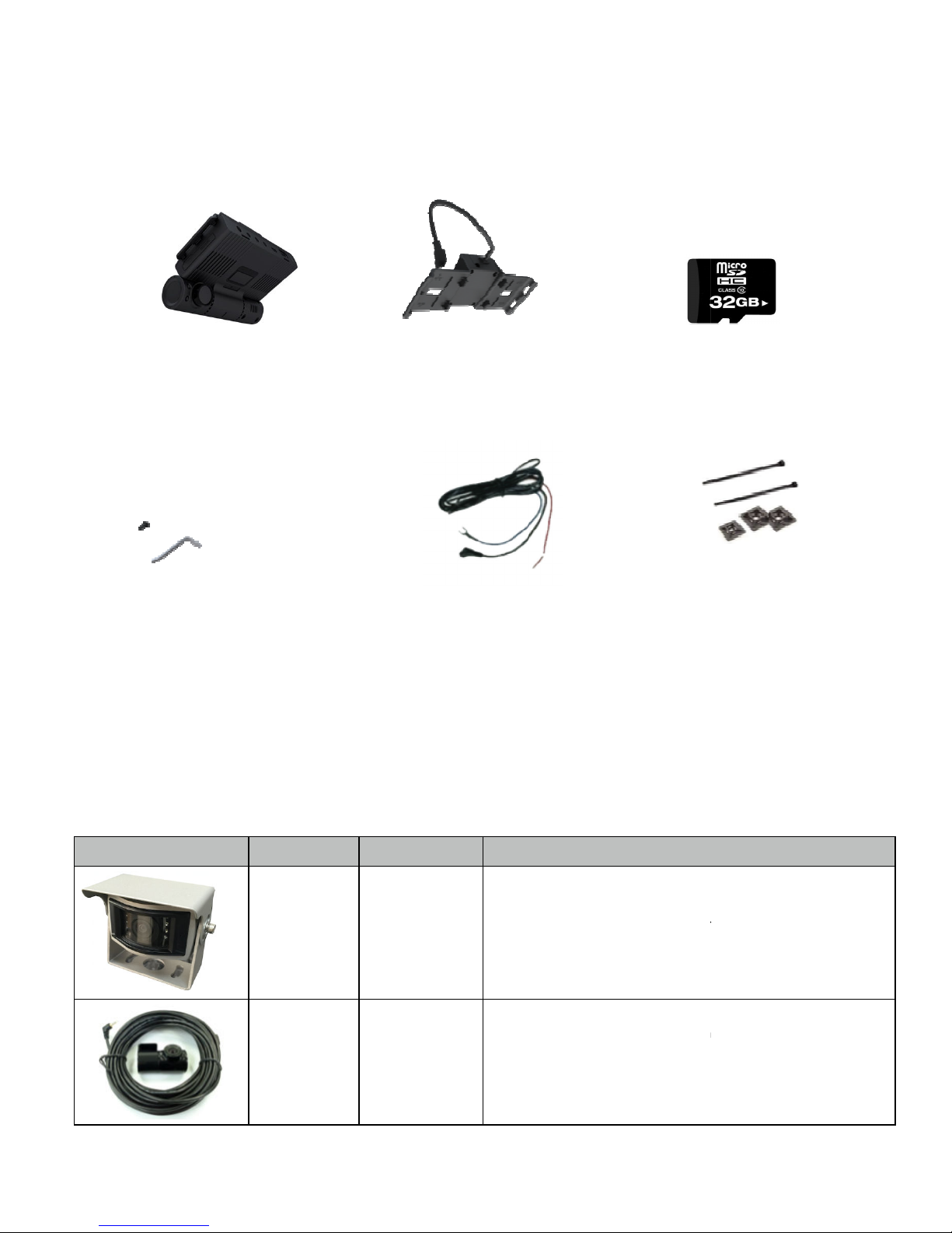
Vandal Resistant Bracket / Screw
he exact appearance of each
Descriptions
infrared
Automatically displays the rear camera
is in use
Camera cable length is around
Micro SD Card
DC Fuse Power Cable
Cable fixing tie & Clips
2.
2.1 System Content
VDR-700 Main Camera
GPS Receiver / Mount
•
differ from picture
2.2 Optional Accessories
Image Model No.
EX7-OMIR
EX7-CMIR
of the system, t
Part Name
Optional 3rd
camera – outdoor
rated
Optional 3rd
camera – Indoor
rated
• Camera cable length up to 60ft
• IP67, 150° wide angle lens,
•
selected and video out cable
• Expansion IR (Indoor Rated)
22 meters for HD truck.
• 170 degrees wide angle
• Reverse gear signal output
accesory may
when reverse gear is
8
Page 9
USER GUIDE V1.0.0
time video can be displayed on an in
Out port (PAL/NTSC compatible)
display
Automatic brightness adjustment
the driver to discreetly
trigger an event/alarm recording
event button on the main device
5 cable length.
Video
hotspot connection to local
r external USB flash memory
Replacement GPS Receiver / VDR camera mount
Prevents access to SD card and cables
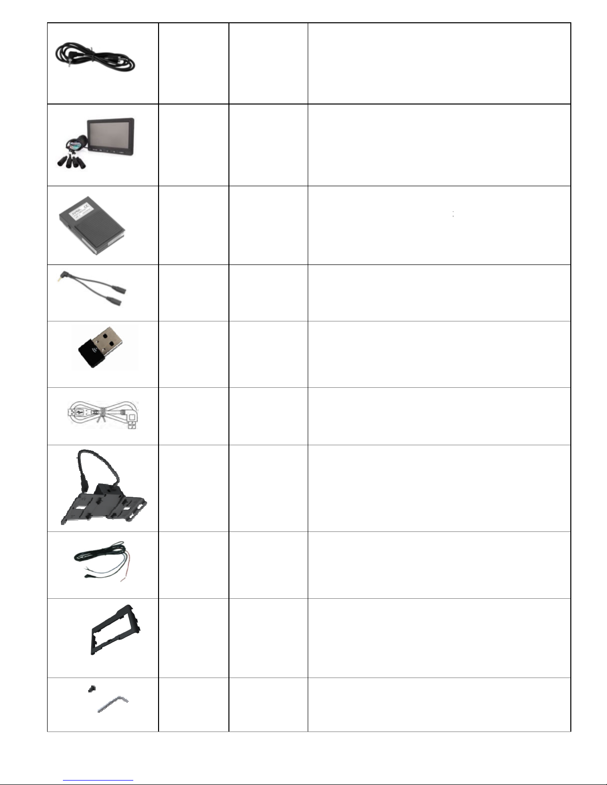
EX7-VOC
Video Out cable
• Real-
via the Video-
• RCA Male
• 3ft cable length
• UL Approved.
-cabin LCD monitor
VLCD
EX7-EFP
EX7-YCB
EX7-WIFI
LCD monitor
SOS Foot S/W
Y-Type Cable
Wireless LAN USB
Adaptor
• 7” wide LCD monitor (16:9) to
cabin
• Resolution RGB 800x480
•
• Adjustable mounting options
• Requires EX7-VOC
• Emergency Foot Switch enables
• Alternative to pushing the
• IP 54 steel construction, 15ft
• 10A / 250VAC
• Required If using EX7-EFP and
simultaneously
• Wi-Fi(Wireless LAN) adaptor for
smartphone (Android App)
• 10ft proxmity
real-time video in-
to bookmark such event
-out cable
EX7-USB1
EX7-BKT
EX7-PWR
EX7-VBK
USB Extension
cable(M-F)
GPS Receiver /
VDR mount
bracket
Permanent Power
Cable
Vandal resistant
bracket
• 6ft USB cable fo
• Right L-Angle type
•
• Replacement power cable
•
• Locks the camera angle
use
EX7-VSW
Vandal resistant
screw / wrench
• Locks the EX7-VBK to the VDR
9
Page 10
10
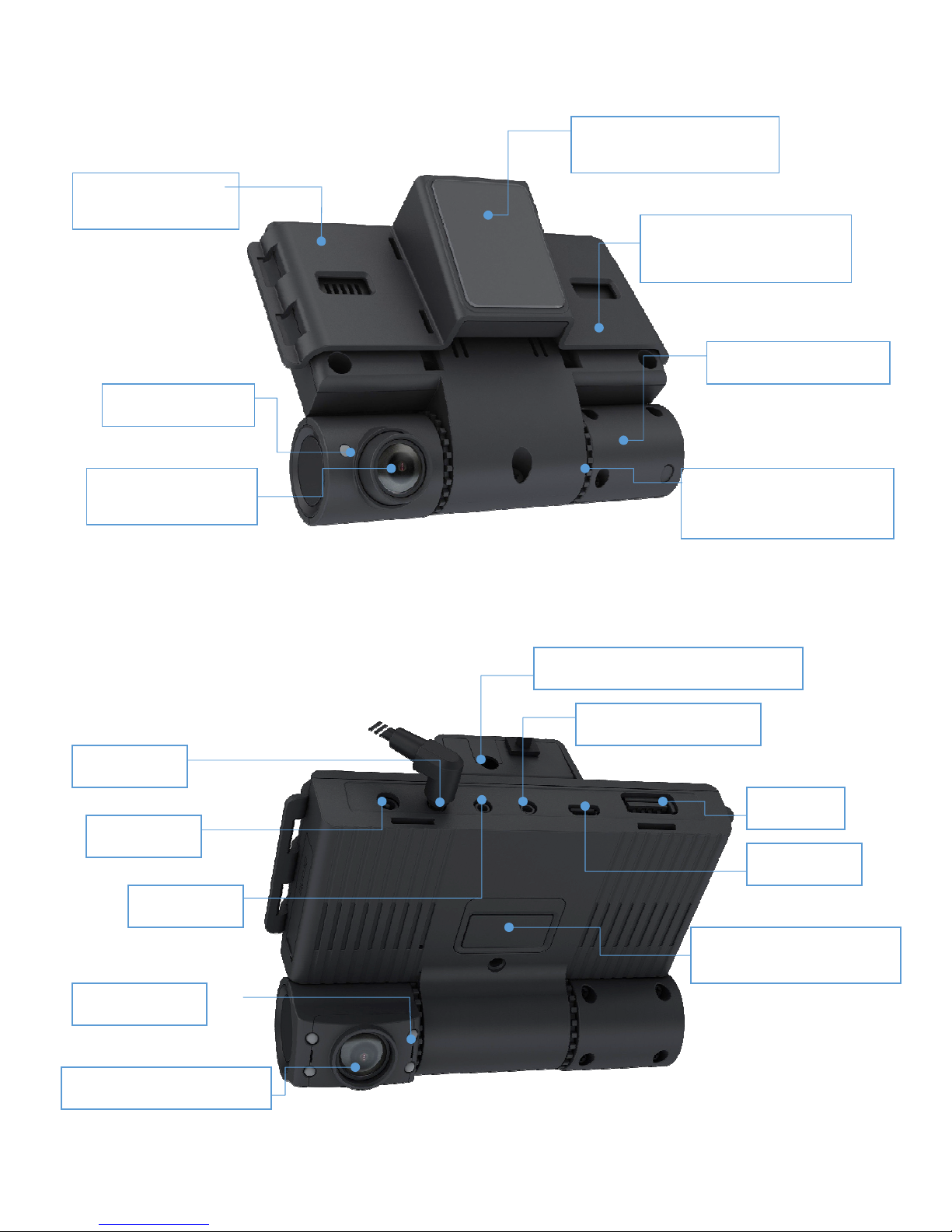
2.3 System Layout
(GNSS Worldwide)
Mount
Road View camera
[Picture 1]
External View
Manual / Event
Tagging
Windshield
Status LED
GPS Receiver Module
Flame retardant
material
In-cabin view
Front Facing /
GPS Port
DC / Power
Video-out
Angle Lock Gear/
Tamper Resistant
External GPS antenna port
3rd Camera port
USB 2.0
Micro USB
IR LEDs
In-cabin camera
USER GUIDE V1.0.0
[Picture 2] Internal View
Page 11
USER GUIDE V1.0.0
3.
Getting ready to start recording
/ Unplug Power
rd cover as shown in the figure
3) Insert the memory card into the card slot until it
is placed as shown
/ Unplug Power
rd cover as shown in the figure
he memory card to eject
Pull the memory card out of the memory
After a period of use, the memory card may get warm. This is normal
is ejected
data loss,
inserti
push the memory card too hard as t
recommended to use
off or removing a memory card during operation such as f
and playback may cause data loss
Inserting and removing SD memory card
ortion of the card is facing up
and not malfunction
n, the VDR will
the power cable
ormatting, deleting,
11
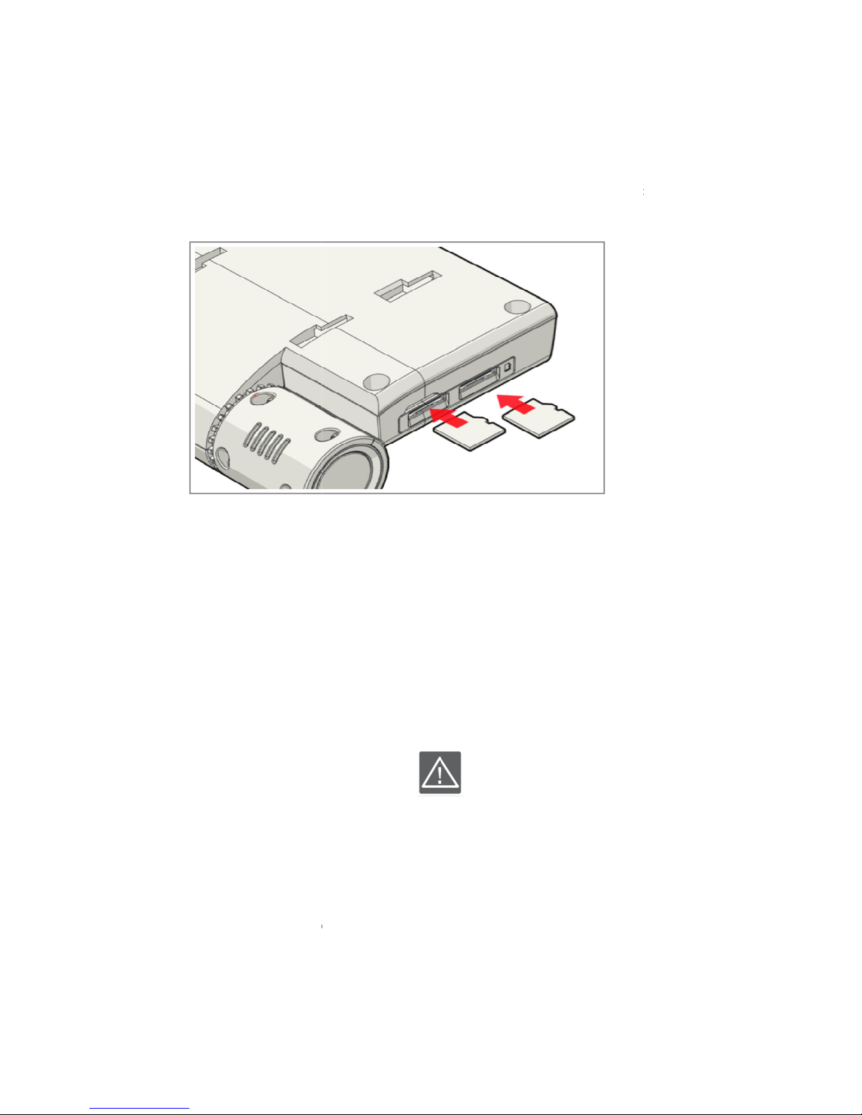
3.1 Insert memory card
1) Turn the VDR off
2) Open the memory ca
* Make sure VDR
4) Close the cover
clicks
below and the terminal p
3.2 Remove memory card
1) Turn the VDR off
2) Open the memory ca
3) Gently push t
4)
• If the memory card
• To avoid damage and or
off the vehicle BEFORE
• Do not
• It is HIGHLY
• Turning the power
recording
card slots and close the cover
from the drive recorder while it is o
power off the system by removing
ng or ejecting the SD card
he memory card may pop out
new SD card to ensure data integrity
operation
shut off
or turning
Page 12
USER GUIDE V1.0.0
memory card and File Format
VDR supports micro SDHC and SDXC cards up to 64GB max
Ventra does not guarantee the operation and stability of the system for SD card exceeding 64GB
Compatible memory card capacity:
Class 10 and up
Class 10 and up
When unspecified memory cards are used, the VDR may not record videos properly and
recordings may be lost or damaged
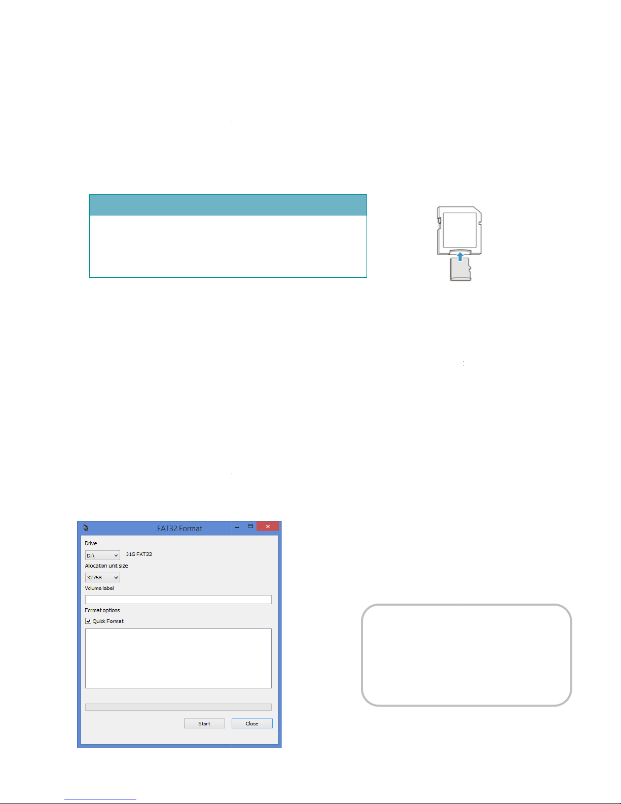
Format the SD card on a PC
FAT32 File Format
up to 32GB, uses Windows built in card format feature found in "
64GB, Ventra recommends using a 3rd party software to format card
Formatting a SD card will permanently delete all information
(32GB = 32768 / 64GB = 65536)
2. To Format 64GB SD Card utilizing 3rd party software, avail
Using the memory card adaptor
To use a micro memory card w
micro card into
card is formatted to such format
www.ventrainc.com
CAUTION
Ventra is not responsible for data loss
due to misuse; including loss caused by
software virus and
12
3.3 Selecting compatible
COMPATIBEL MEMORY CARDS
•
•
•
- SDHC: 4GB~ 32GB
- SDXC: ~up to 64GB
•
card reader, insert
- MLC - Multi Level Cell
- MLC - Multi Level Cell
ith a computer or a
adaptor
per slot
VDR utilizes
For SDXC card
Computer"
For SDXC card with
1. Select memory card size:
- Please ensure the memory
able on Ventra Website
Windows My
PC,
damage
SDXC card
Page 13
USER GUIDE V1.0.0
field of view,
section, below the tint
cabin viewing angle is not blocked by the
Center of Windshield
optimal
or below th
Clean surface area with lint free damp cloth.
Allow 1 minute to dry (Air conditioner)
13
4. Installation
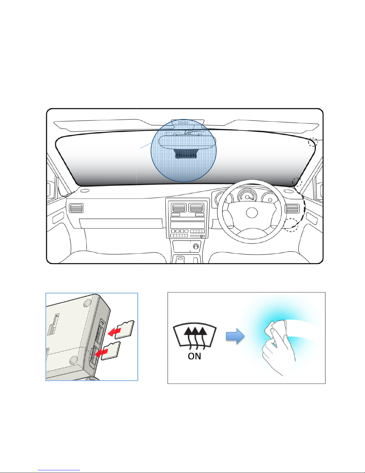
4.1 Placement of VDR
The VDR has a 120-degree
the center top
providing wide-angle recording. The
of the windshield, adjacent to
placement is
e rear view mirror.
Ensure the in-
rear view mirror.
Insert micro SD cards
Page 14
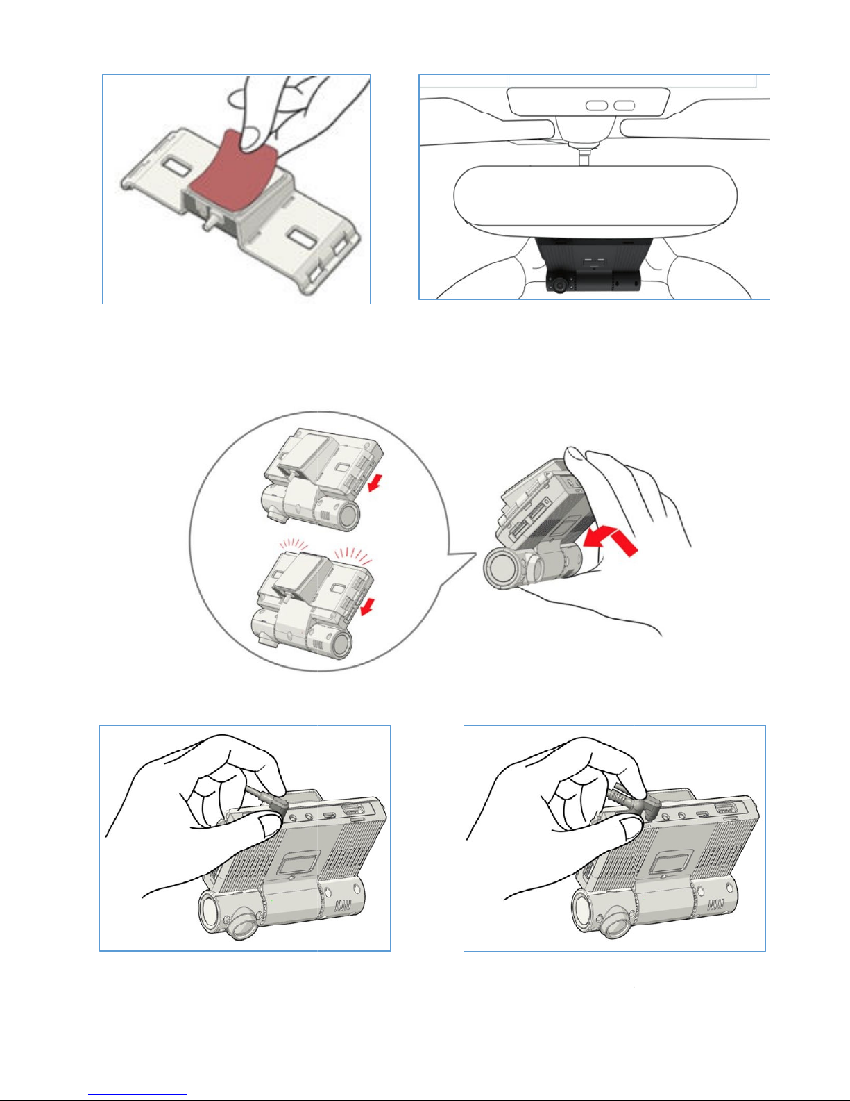
USER GUIDE V1.0.0
Connect GPS cable from the
Remove film from the bracket
Click!
below or adjacent to the
rear view mirror. Press the VDR against the windshield
for at least 10 seconds to ensure firm adhesion
Connect DC Power Plug into VDR
(DC IN)
Please ensure the mount bracket is
securely connected to the VDR
14
Install VDR on windshield -
cradle into the VDR (GPS IN)
Page 15
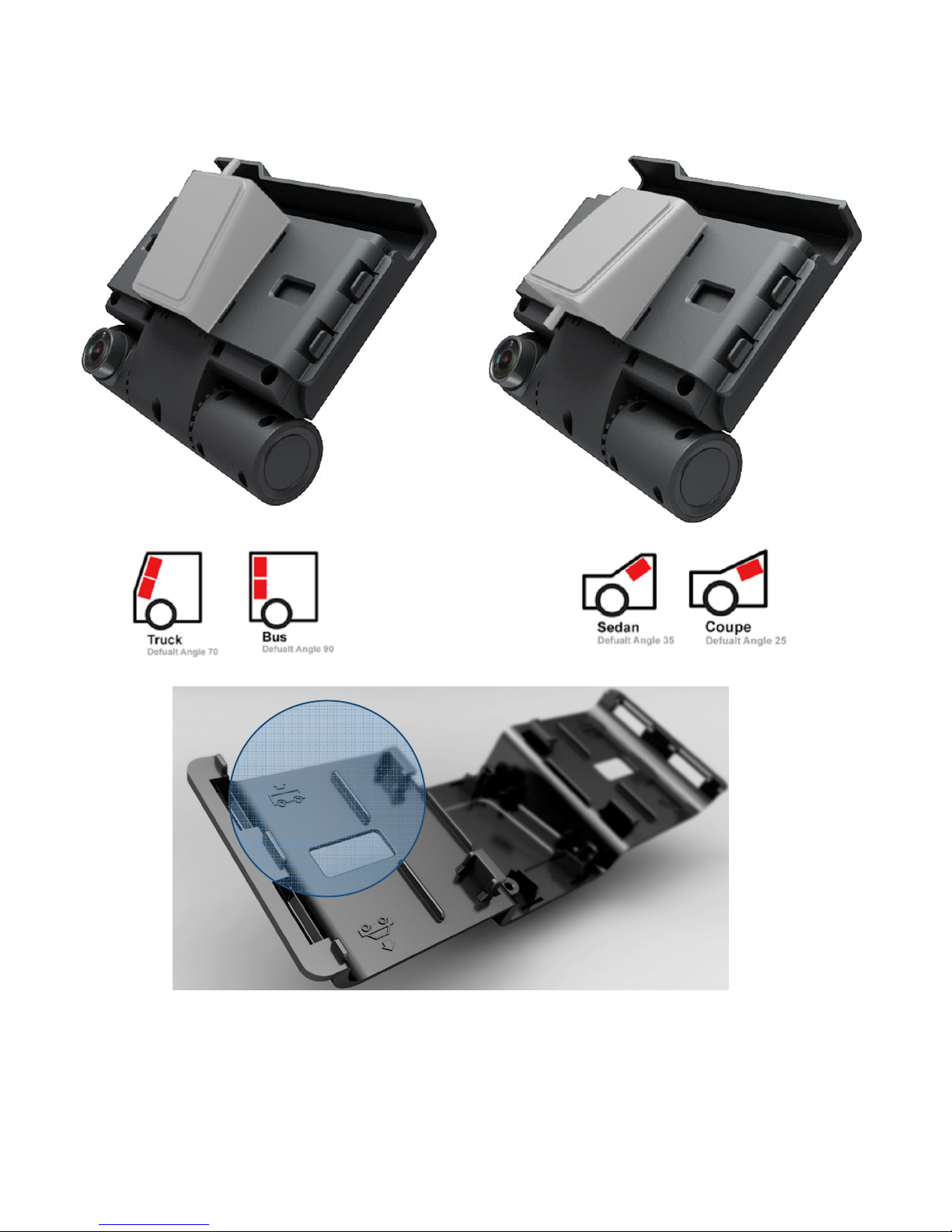
15
VDR is designed with a multi-directional bracket to support different vehicle windshield.
Please refer to the figure below for the appropriate installation angle
Refer to installation angle guide inside the bracket
USER GUIDE V1.0.0
Page 16
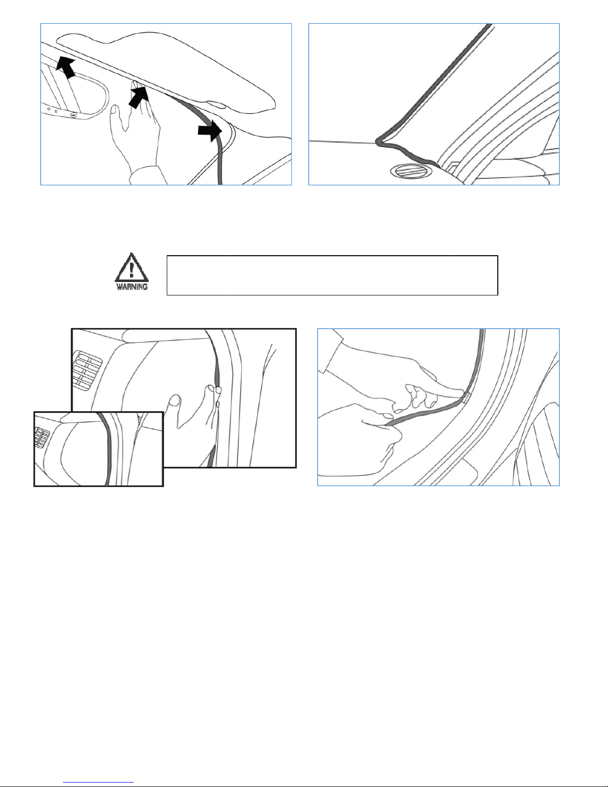
USER GUIDE V1.0.0
Tuck the power cable into the windshield
Fit the power cord to the side of the
: Do not use sharp object to force power cable as it
may damage the wire and risk injury, fire and electrical shock
Continue to tuck power cable
Fit the
power cord along the door frame
and into the power source
16
along the side pillar
Warning
dashboard
Page 17
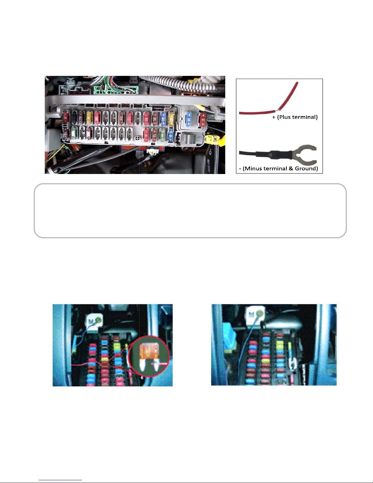
USER GUIDE V1.0.0
.2 Vehicle FUSE connection
Red (Positive) and Black (Negative / Ground)
power cable included with the system.
Open the fuse box to identify power terminal for constant power source such as trunk, head lamps,
Cabin lights, etc., Fuse information are typically listed in the vehicle's owner manual and or the
dependent upon vehicle type
Connect
Positive
terminal cable
CAUTION
nstallation by a Professional technician is highly recommended
Please exercise caution when connecting the power to prevent shock. Do not use sharp object to force cable
Vehicle battery will be drained if unoperated for an extended
battery. Please disconnect the power plug from the VDR if vehicle will be parked for longer than 1 week
for installation. Use the
(RED
Connect Minus terminal (BLACK color)
bolt or metal frame of vehicle
period of time depending on the size of the
17
4
VDR requires 2 wires -
I
for power supply
Inback of the fuse cover
* Fuse box location may vary
color) to Ignition or Acc. Fuse
to
Page 18
USER GUIDE V1.0.0
Safety Precautions
or adjust the angle
serious injury or death
is on, it is normal for the system
angle
lens
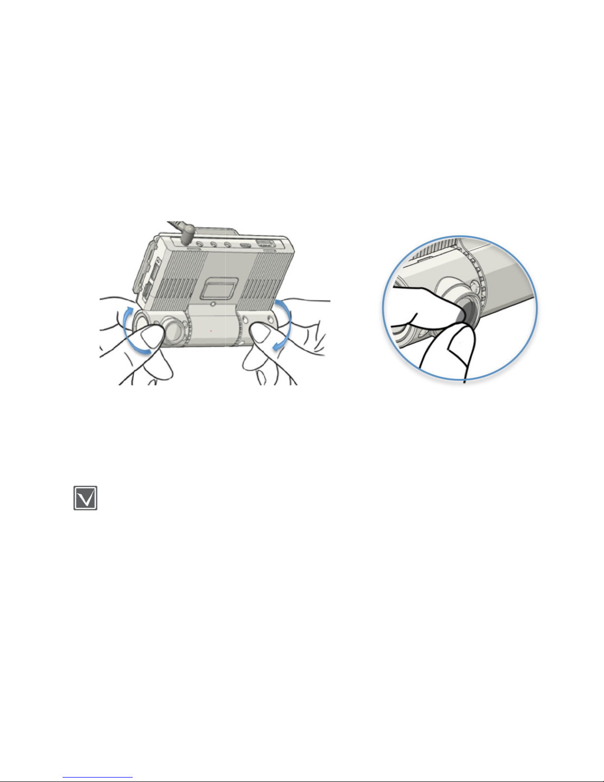
Adjusting angle of cameras.
y cause
arm. Please handle with care
which can affect image
Remove lens cover
18
• Do not operate
and result in
• While the VDR
4.3 Adjustment camera
Avoid touching the
quality
of VDR while driving as it ma
to be w
to minimize fingerprint or smudge
vehicle accident
Page 19
19
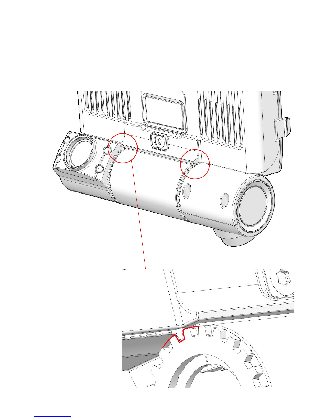
Fit tamper resistant case tab into camera angle gear to lock camera angle
4.4 Tamper resistant enclosure
USER GUIDE V1.0.0
Page 20
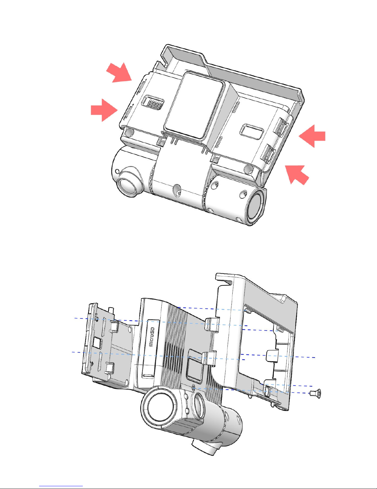
20
Insert tamper resistant case into the GPS mount
Lock the screw into the tamper resistant case via wrench.
USER GUIDE V1.0.0
Page 21
21
5. Recording
5.1 Video resolution
The VDR has two (2) built in high-definition HD CMOS image sensors and are made of glass for
optimal lens and video quality. The glass lens has superior performance than plastic lens,
especially in high temperature environment
The VDR records 1280 x720P HD resolution for Front and In-Cabin view camera. Optional 3rd
camera records in D1 resolution - (720 x 480)
5.2 Overlay information
USER GUIDE V1.0.0
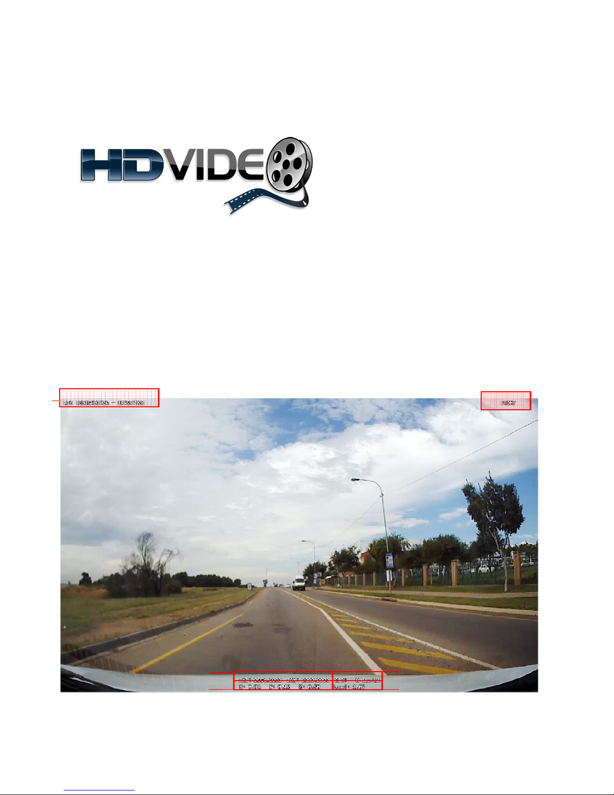
[Figure 6.2.1 / Information overlay on Front Video]
Page 22

22
[Table 6.2.1 / Descriptions of information overlaid on Front Video]
①Camera View
②Time Information
“ Front” is overlaid on the video
VDR can select 3 types of time information
The time information can be configured in the systems settings
[Option 1: ONLY RTC are displayed]
When Daylight Savings Time is OFF
RTC [YYYY:MM:DD - HH:MM:SS]
When Daylight Savings Time is ON
DST [YYYY:MM:DD - HH:MM:SS]
[ Option 2: ONLY UTC are displayed]
UTC [YYYY:MM:DD - HH:MM:SS]
[ Option 3: BOTH RTC&UTC are displayed]
When Daylight Savings Time is OFF
RTC [YYYY:MM:DD - HH:MM:SS]
UTC [YYYY:MM:DD - HH:MM:SS]
When Daylight Savings Time is ON
DST [YYYY:MM:DD - HH:MM:SS]
UTC [YYYY:MM:DD - HH:MM:SS]
③GPS Coordinates
④Speed
⑤G-Sensor
Values (Gx, Gy, Gz)
GPS coordinate / Route history are recorded via built-in passive GPS.
Weather and or environment may affect signal quality and accuracy.
When VDR cannot receive GPS data, each of the value filed is
displayed as “ - ”
The speed of the vehicle is calculated by GPS signal. Weather and or
environment may affect signal quality and accuracy
G Sensor value in 1, 2, 3G format
The section shows X-axis value (Gx), Y-axis value (Gy) and Z-axis value
(Gz)
USER GUIDE V1.0.0
Page 23
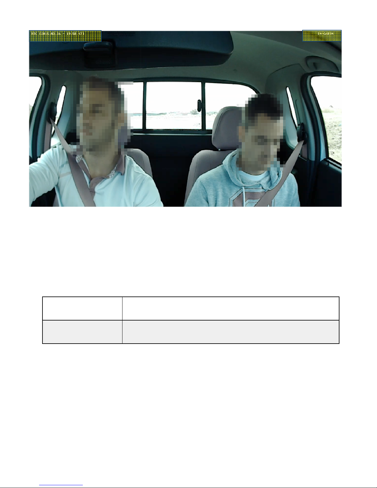
USER GUIDE V1.0.0
[ Figure 6.2.2
Descriptions of
CABIN” is overlaid
This field has the same value as Table 6.2.1
CABIN
23
/ Information overlay In-cabin Video ]
[Table 6.2.2 /
①Camera View
②Time Information
“ IN-
information overlaid on IN-
Video]
Page 24
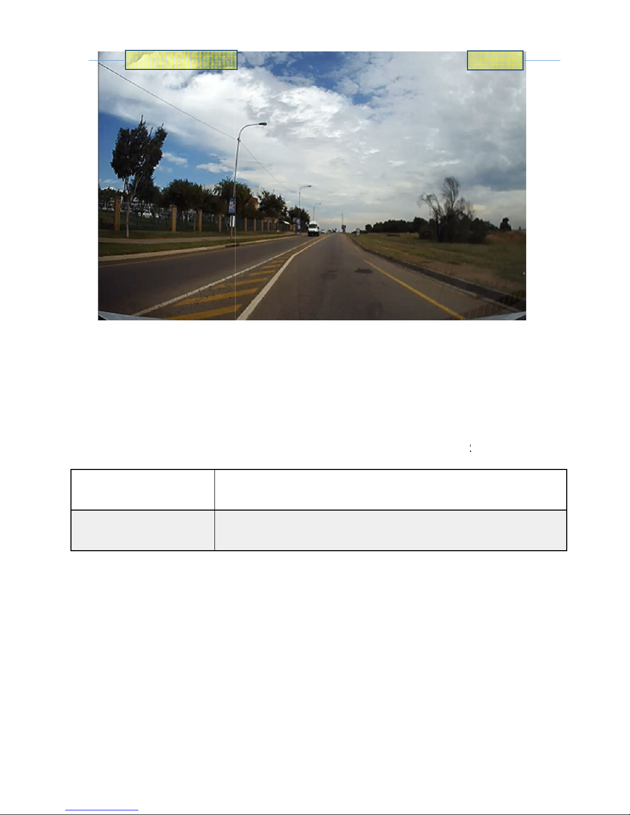
USER GUIDE V1.0.0
[Figure
6.2.3
Descriptions of
“ REAR” is overlaid
This field has the same value as Table 6.2.1
information overlaid on REAR
24
/ Information overlaid on rear video]
RTC [2015:03:26 - 19:58:47]
[Table 6.2.3 /
REAR
Video]
①Camera View
②Time Information
Page 25
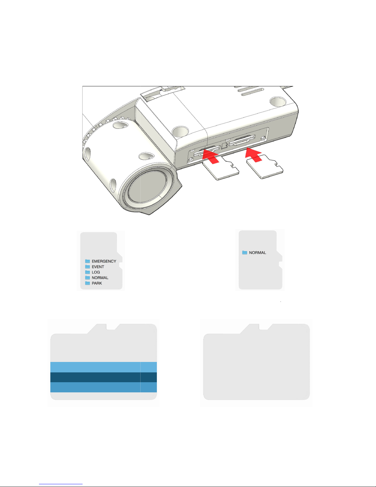
USER GUIDE V1.0.0
Storage / File Allocation
The drive recorder prepares 4 types of directories and system margin area in Primary SDHC and
Primary Memory storage allocation
Area
Primary memory slot
Secondary Memory storage allocation
File
slot
25
slot
5.3 Memory Card
Secondary SDHC slot.
74% Normal, Emergency File
1% LOG File Area
10% EVENT File Area
10% PARK File Area
5% System Margin Area
=
Primary memory slot
Secondary memory slot
95% Normal, Emergency
=
5% System Margin Area
Secondary memory
Area
Page 26
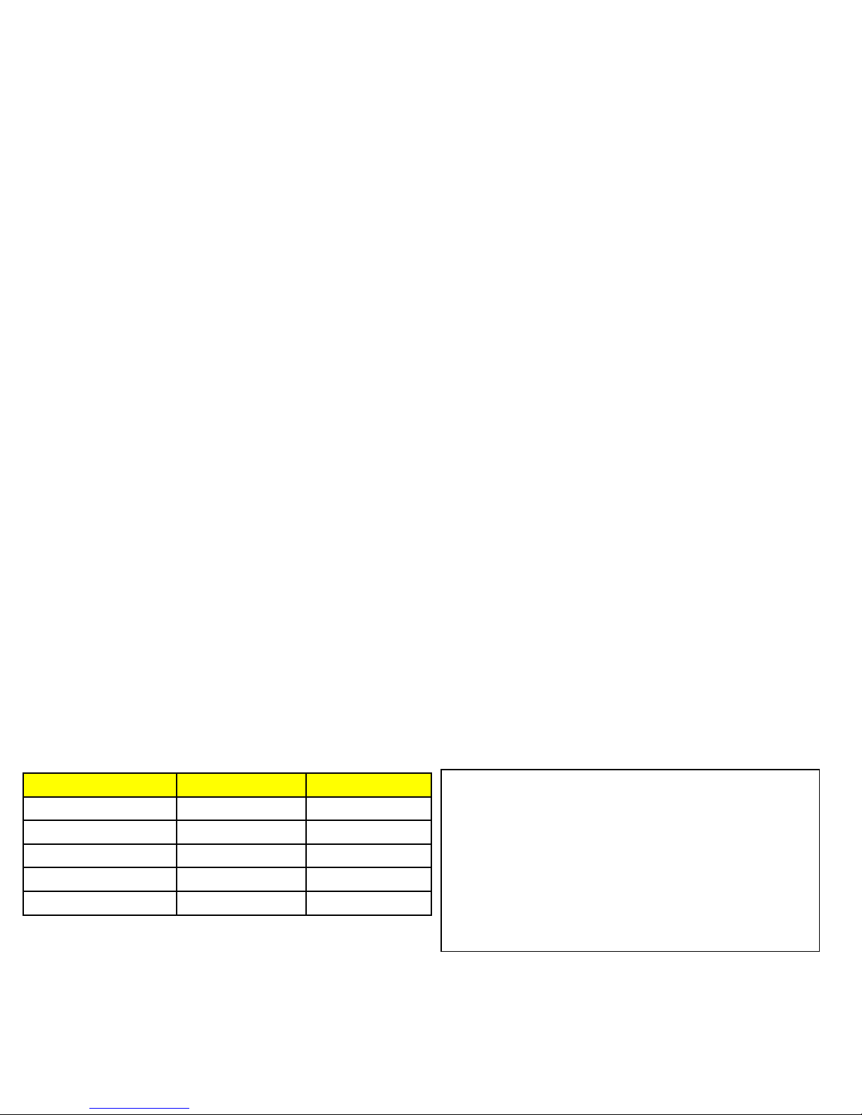
26
5.3.1 Directory of NORMAL recording file area
• Allocate 74% in PRIMARY SD Memory, 95% in SECONDARY SD memory
• Drive recorder stores 60 seconds of video per file in NORMAL recording
• When card reaches full capacity of NORMAL file area in one SD memory card, system will then store NORMAL
recorded files in NORMAL file area of the SECONDARY SD memory card. When it reaches full capacity of NORMAL
file area in both SD card, VDR will then overwrite Normal video files in this area (delete the oldest file and replace
with the newest file) - also known as Cycle Recording
5.3.2 Directory of EVENT video file area
• Allocate 10% in PRIMARY SD Memory
• VDR stores the 30 seconds (15 Pre/ 15 Post) video file in EVENT file area
5.3.3 Directory of EMERGENCY video file area
• Allocate area to with NORMAL Video file area
• System stores 30 seconds video file in EMERGENCY file area
5.3.4 Directory of LOG area
• Allocate 1% in primary SD memory.
• VDR stores Event Logs, Sensor Logs, Accident Event, GPS Data in this area
• Drive recorder stores Accident Event Log
• A GPS Log can be up to 1MB. When the log file reaches 1 MB, system will create a new log file and continue to
record GPS data
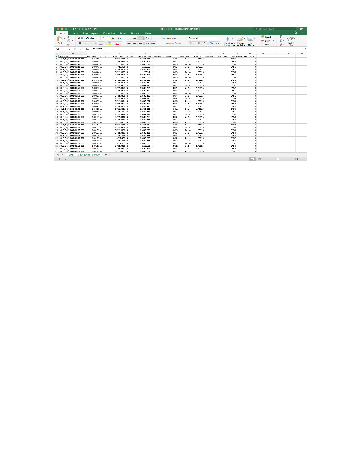
• System stores G-Sensor data in 20[Hz] as G-Sensor Log
• Drive recorder records G-Sensor data as a CSV format
• A G-Sensor Log can be up to 1MB. When the log file reaches 1 MB, system will create a new G-Sensor log file and
continue to record G-Sensor data
• During VDR system starts-up, it will check the recorded dates of GPS Logs and G-Sensor Log
Storage Primary slot Secondary slot
Normal/Emergency 74% 95%
Event 10% N/A
Park 10% N/A
Log 1% N/A
System Margin 5% 5%
• If one SD memory was inserted in only Primary SD
memory slot of VDR, system operates according to
the allocation of Primary SD slot
•
If one SD memory was inserted in only Secondary SD
memory slot of VDR, system operates according to
the allocation of Primary SD slot. NORMAL video file
area and EVENT video area are saved in the SD
memory
USER GUIDE V1.0.0
Page 27
USER GUIDE V1.0.0
[Figure 6.3.4
[Figure 6.3.4
27
-1 Log File / Accident-event]
-2 Log File / G-Sensor]
Page 28
USER GUIDE V1.0.0
28
[Figure 6.3.4-3 Log File / GPS]
Page 29
29
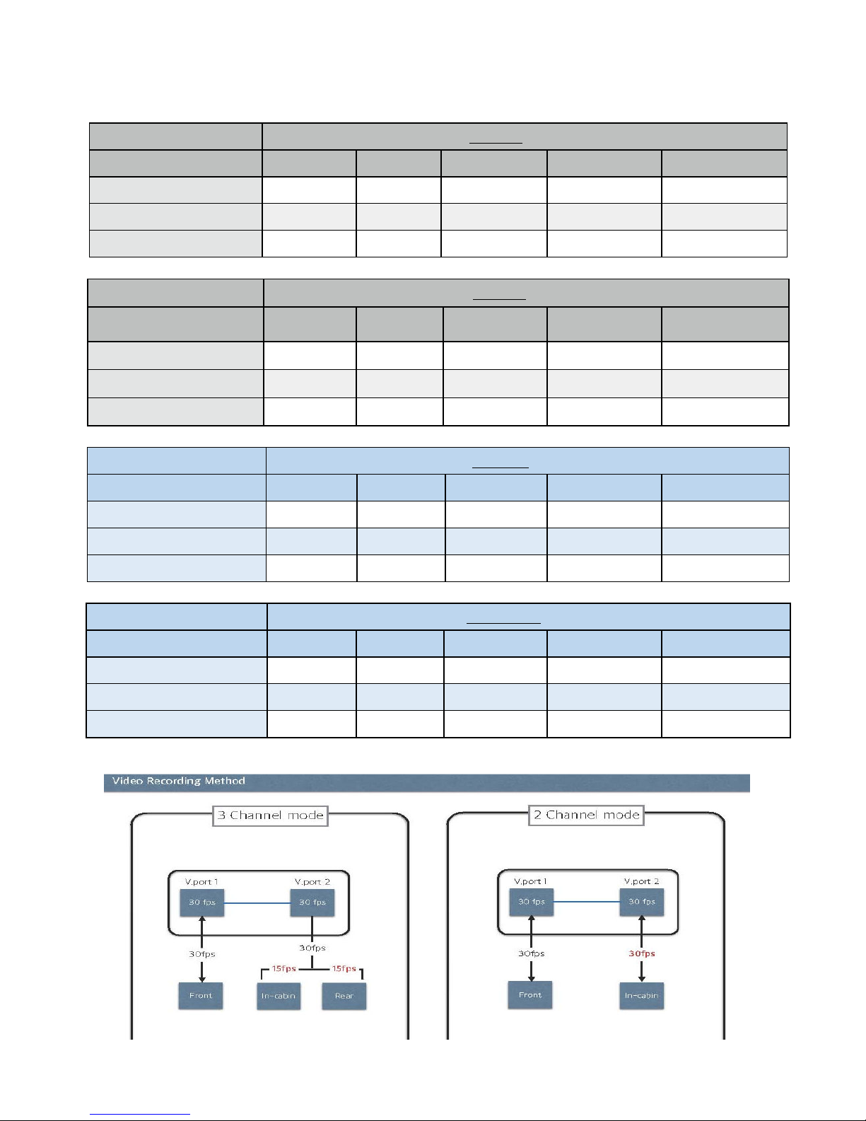
6. Recording Time / Frame
• These recording time are approximate and may vary based on actual recording conditions
Normal Quality 2 Channel - PRIMARY Memory / Sound OFF
Video Frame/s 4 fps 5 fps 10 fps 15 fps 30 fps
16GB 22h 15m 18h 59m 9h 20m 6h 15m 3h 17m
32GB 43h 29m 37h 17m 18h 40m 11h 50m 6h 34m
64GB 99h 14m 85h 12m 42h 13m 26h 33m 14h 53
Normal Quality 2 Channel - PRIMARY Memory / Sound ON
Video Frame/s 4 fps 5 fps 10 fps 15 fps 30 fps
16GB 16h 43m 14h 60m 8h 14m 6h 15m 3h 37m
32GB 33h 26m 29h 21m 16h 28m 11h 50m 6h 34m
64GB 75h 24m 67h 28m 37h 29m 26h 33m 13h 59m
Normal Quality 3 Channel - PRIMARY Memory / Sound OFF
Video Frame/s 4 fps 5 fps 10 fps 15 fps 27 fps
16GB 29h 21m 23h 59m 12h 35m 8h 33m 4h 38m
32GB 58h 41m 47h 18m 24h 30m 16h 26m 8h 37m
64GB 134h 16m 108h 03m 54h 72m 36h 32m 18h 24m
Normal Quality 3 Channel - SECONDARY Memory / Sound ON
Video Frame/s 4 fps 5 fps 10 fps 15 fps 27 fps
16GB 20h 18m 18h 09m 10h 22m 7h 13m 4h 16m
32GB 39h 57m 35h 38m 20h 44m 14h 26m 7h 51m
64GB 91h 01m 81h 03m 47h 21m 33h 06m 17h 20m
(Unit: Approximate hour of recording in “NORMAL” folder)
USER GUIDE V1.0.0
Page 30
USER GUIDE V1.0.0
7. LED Signal
LED Signal
30
7.1 LED Status Indicator
Operating state
System Booting
( Approx. 30 sec.)
Re-Booting
(Approx. 20 sec.)
Firmware Updating
(Approx. 1 minute)
Operating state
Connecting External
Device (Wi-Fi/3G/4G)
Memory card not
inserted / Entering
CCTV mode
GPS signal detected
LED Signal
Normal Recording
: LED LAMPs Blinking state
Event recording
Page 31

31
8. Ventra Software PC Requirement
8.1 System Requirement
Items System Requirements
OS
CPU
RAM 2GB or higher is recommended
Video Card
Display
USB USB 2.0
Direct X DirectX 9.0c or higher
Microsoft Windows XP SP2, Windows Vista, Windows 7, Windows
8 or higher
Intel® Core 2 Duo® 1.66 GHz or higher is recommended
AMD Athlon™ X2 Dual-Core 2.2 GHz or higher is recommended
(Notebook: Intel Core2 Duo 2.2GHz or AMD Athlon X2 Dual-Core
2.6GHz or higher is recommended)
NVIDIA GeForce 8500 GT or higher,
ATI Radeon HD 2600 series or higher
1024 x 768, 16-bit color or higher (1280 x 1024, 32-bit color
recommended)
Recommended Memory Card
(Installed in Camcorder)
• System requirements mentioned above are recommendations. Even on a system that
satisfies the requirements, PC Manager may not operate optimally
• On a slower than recommended computer, video playback may skip frames or operate in
an unexpected manner
• If the version of DirectX on your computer is lower than 9.0c, install DirectX 9.0c or higher
• We recommended you transfer recorded videos to a PC before playing back or editing the
videos
• To run PC Manager, a laptop computer requires faster and better components than a
desktop PC.
• PC Manager is not compatible with Mac OS
• On 64-bit environment of Windows XP, Windows Vista, and Windows7, PC Manager may
be installed and work as 32-bit program
USER GUIDE V1.0.0
40MB/s (Class 10) or above
Page 32
32
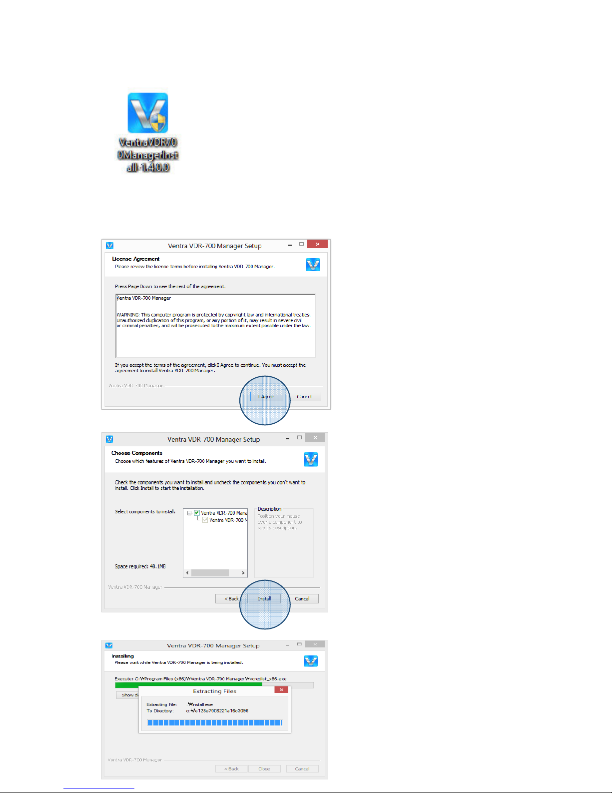
Click "Install" to continue
8.2 Install VDR-700 Software
1. Double Click and run ‘Ventra VDR700 Manager’ install program file
2. Click to “I Agree” for next step of Installation
USER GUIDE V1.0.0
Page 33
33
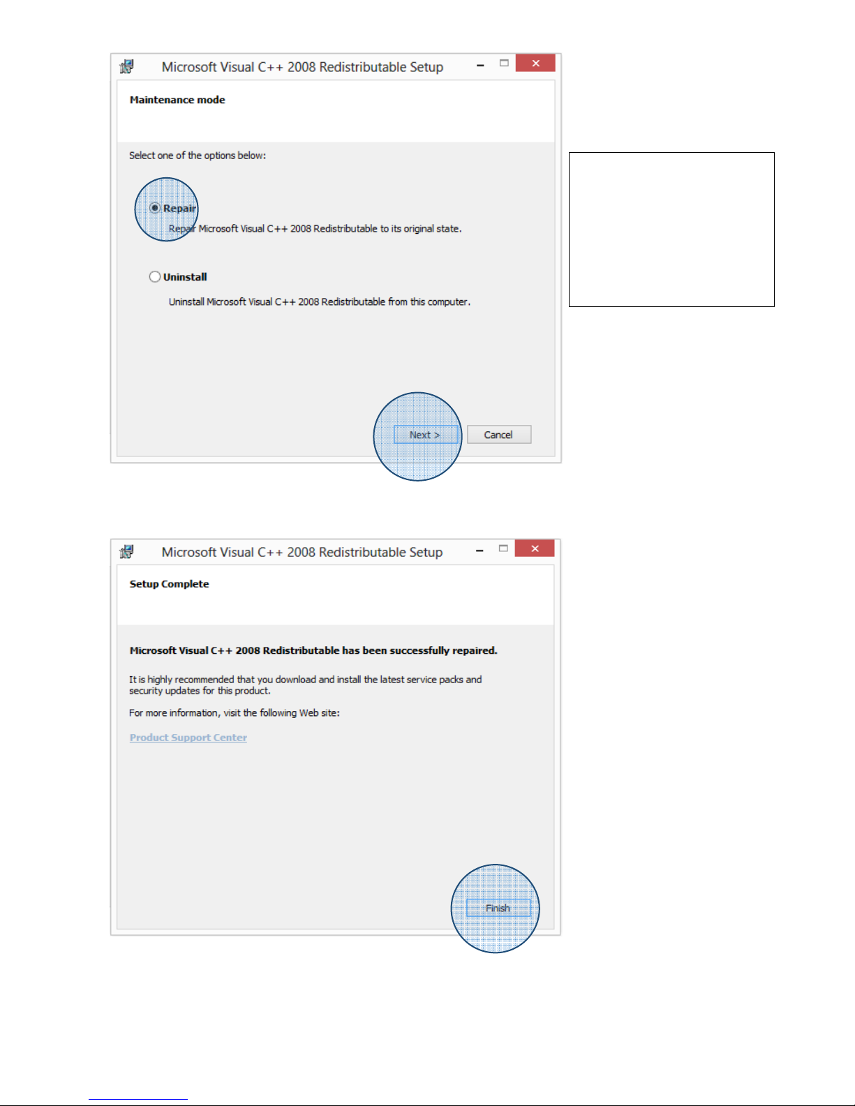
Ventra VDR PC Manager
requires Microsoft Visual
C++, so this step simply
sets up the required
updates.
Please select REPAIR
USER GUIDE V1.0.0
Page 34
USER GUIDE V1.0.0
34
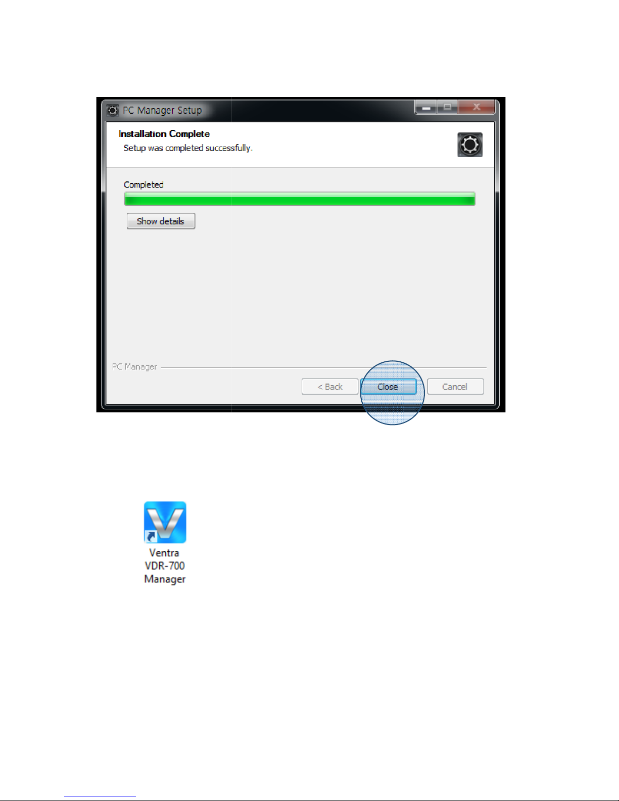
3. Click desktop icon to run
Ventra VDR-700 Manager program
Page 35
35
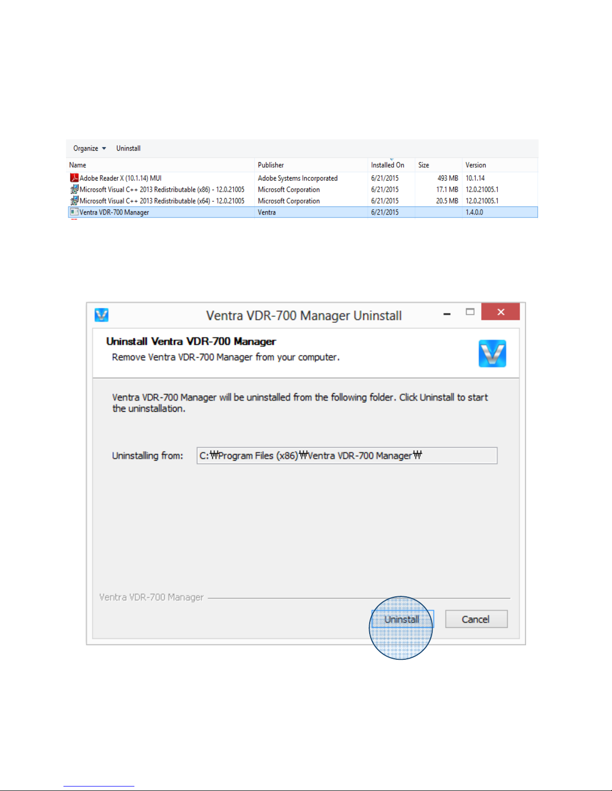
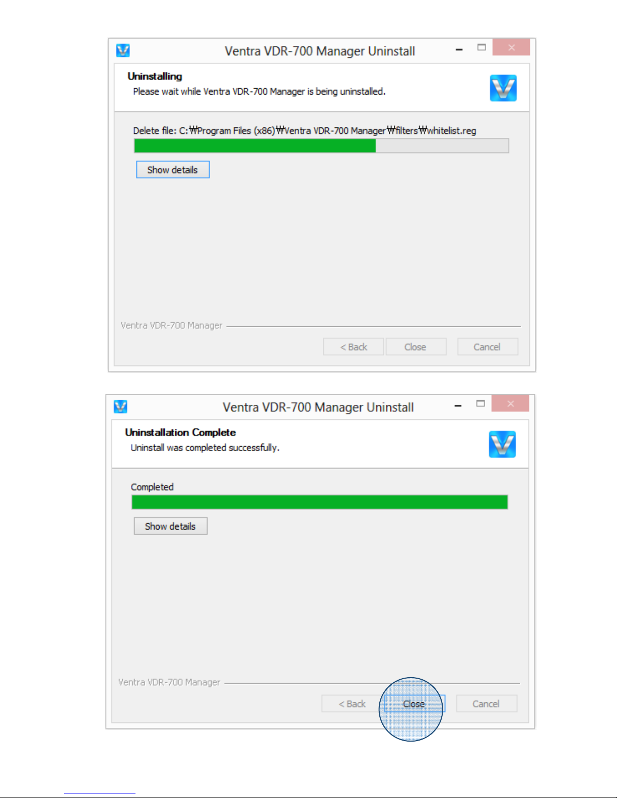
8.3 Uninstall PC Manager
1. Click to Ventra VDR-700 Manager in Control panel.
2. Click to Uninstall for next step of uninstallation
USER GUIDE V1.0.0
Page 36
36
USER GUIDE V1.0.0
Page 37
USER GUIDE V1.0.0
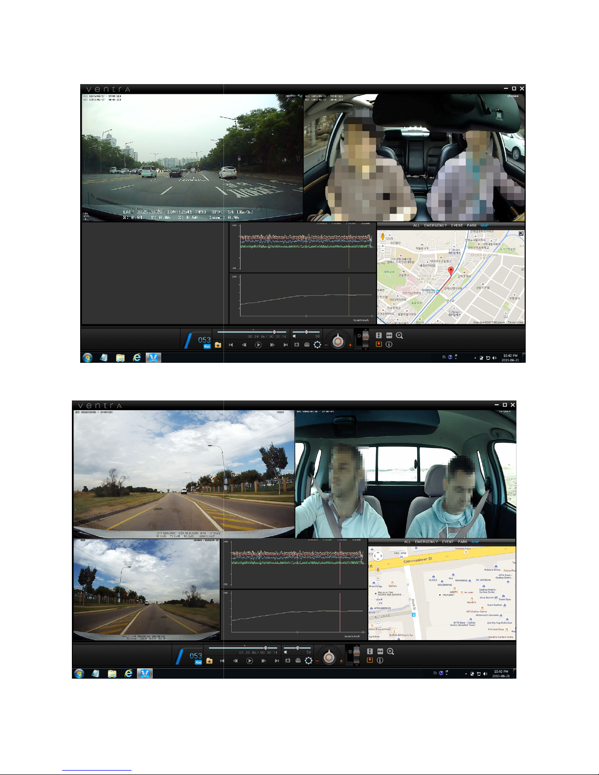
8.4 VDR-
700 Software Overview
37
2 Channel View
3 Channel View
Page 38
USER GUIDE V1.0.0
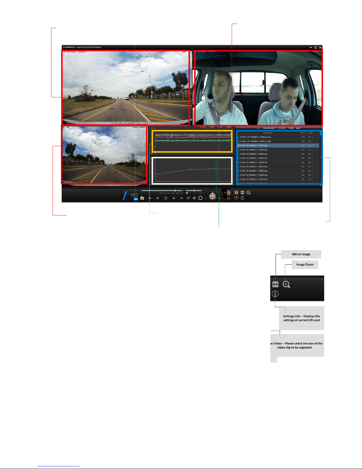
Front Camera View
Camera
Speed
Graph
38
In-cabin
View
3rd Camera /Rear
G-Sensor Graph
Camera View
File list / Map
Page 39
USER GUIDE V1.0.0
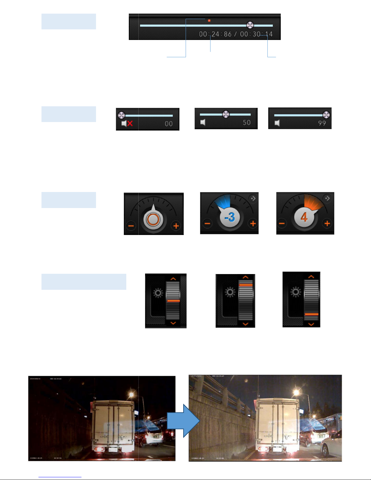
Event marker
Playback Track
Play Speed
Video Brightness Control
Normal
Normal
Slow Level
Normal
Brighter
Brighter
39
Max
Fast Level
Darker
Sound control
Track time
Mute Middle
Total time per file
Page 40
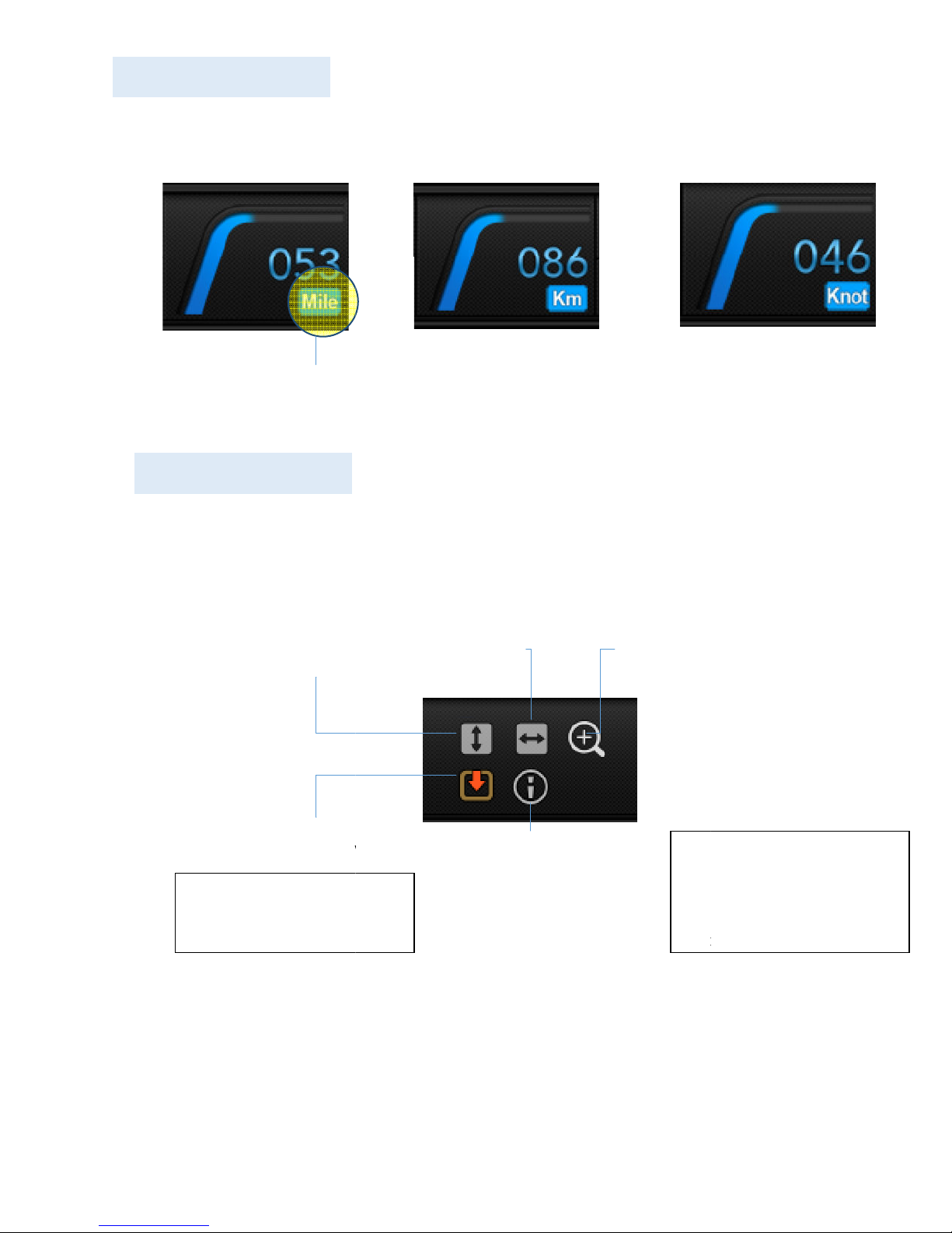
USER GUIDE V1.0.0
Speed Indicator
Click to change
speed unit
MPH
Other
Flip video
File download
Km Knot
Image Zoom
Settings
The system information
indicates the
Vehicle ID,
of the firmware and
40
Save and export the
selected video files
Reverse video
VDR Information /
Driver /
current version
Page 41
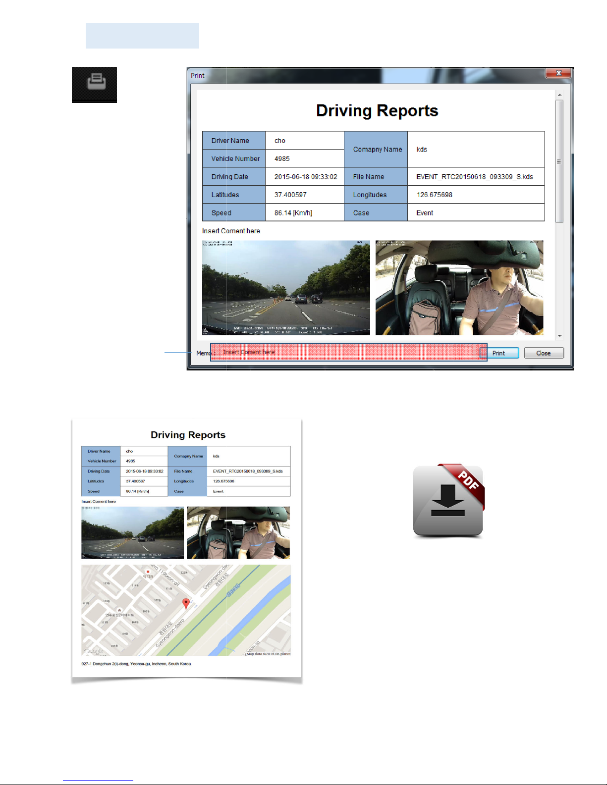
USER GUIDE V1.0.0
Incident Report
If a PDF program is available, reports
may also be printed / converted to PDF
41
Insert comments
Click here to print
Page 42
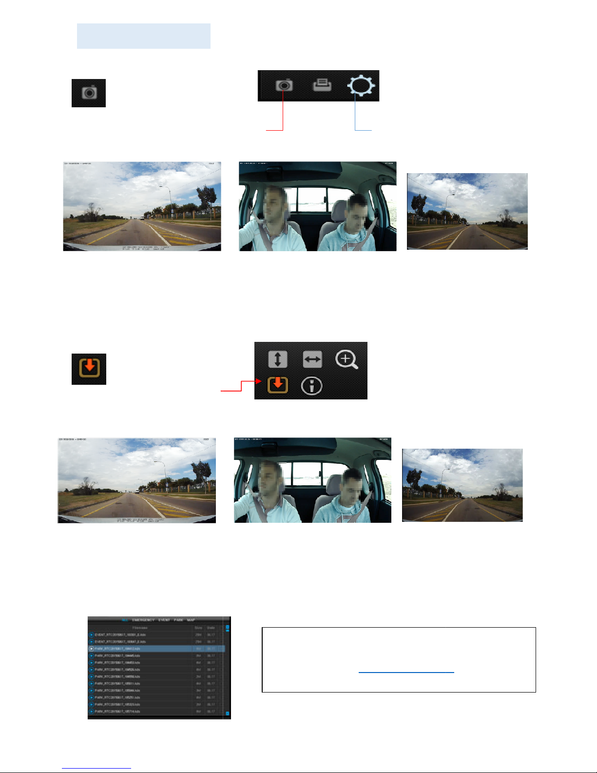
USER GUIDE V1.0.0
To save an image, click on the camera icon
Select the file destination on PC
cameras are exported (If optional 3
To save video, check the box of the file to be exported from the recording file list
destination
cameras are exported (If optional 3
Save and Export
Save JPG images
Front view
video
camera is installed)
camera is installed)
Setting configuration
20150327_003333_
camera
20150327_003333_
In-cabin view
video
camera video
VDR utilizes proprietary file format. To view
700 software is required and can
www.ventrainc.com
42
IMAGE
Front view JPG image
In-cabin view JPG image
3rd
JPG image
20150327_003333_CH1.jpg
-
-
- Images from all 3
VIDEO
20150327_003333_CH1.kds
-
- Select the file
- Videos from all 3
20150327_003333_CH2.jpg
20150327_003333_CH2.kds
on PC
CH3.jpg
rd
3rd
CH3.kds
rd
recordings, the VDRbe downloaded at
Page 43
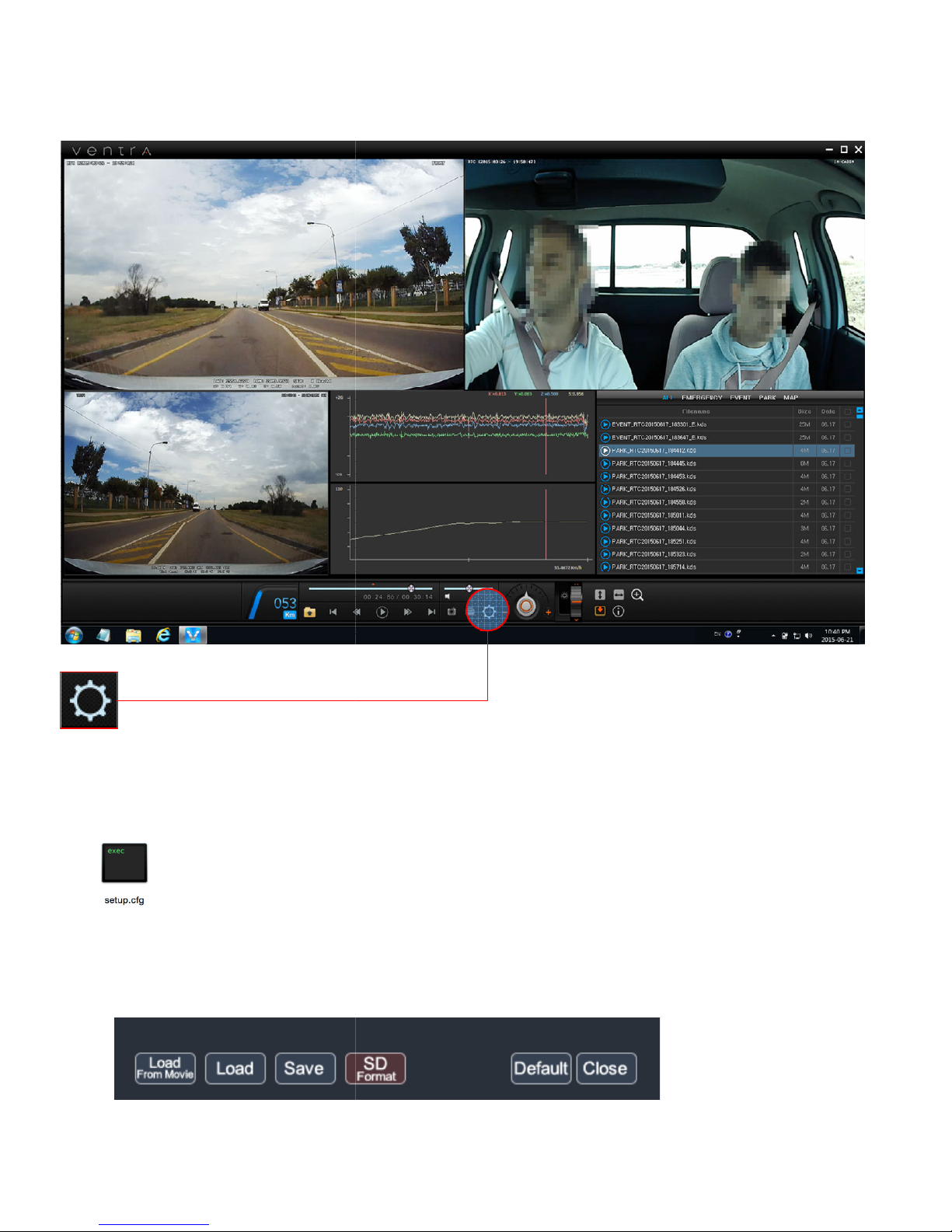
USER GUIDE V1.0.0
8.6 Setting configuration
can be used to manage from a single car to an entire fleet of vehicles.
, ID and speed limit
along with administrative password for secure access.
Configuration settings are saved as “
Setup.cfg files can be used as
from File to setup each vehicle from Setup.cfg
assigned to each SD card for every vehicle
manage /
for all vehicles to save time for fleet setup
43
The Ventra software
Customizable settings
Select Load
Setup.cfg” file and is used to
a template
can be
update VDR-700
Page 44

USER GUIDE V1.0.0
8.6.1 Record setting
Enable only when an optional 3
Per Second (FPS) value appli
the longer the recording time
Motion Detection
Enable / Disable
Inverting of camera angle
Inverting of camera angle
Reverse
Import previou
ing value from ‘setup.cfg’ file
Format SD card in FAT32 format
ase use separate format program available
CAUTION: Formatting the SD card will erase all content. Please back up data if necessary
default settings
Note: NO settings are saved when e
SAVE
es to both front view cameras
capacity on the memory card
System automatically records
support up to 32GB. If SD card capacity is greater
44
- 3 Channel Mode:
- Recording FPS: This Frames
The lower frame value,
- Sleep Mode:
motion is detected
- Audio Record Enable:
- Front Camera Flip:
- In-Cabin Camera Flip:
- Rear Camera Reverse:
- Load From Video:
- Load: Import previous sett
- Save: Save settings
-
- SD Format:
than 32GB, ple
- Default: Restore factory
- Close: Exit setting menu (
To save and exit, click on
rd
camera in connected
Mode while vehicle is parked.
Microphone for audio recording
camera angle
s setting value from video file
on www.ventrainc.com
button
when
xiting via CLOSE)
Page 45
USER GUIDE V1.0.0
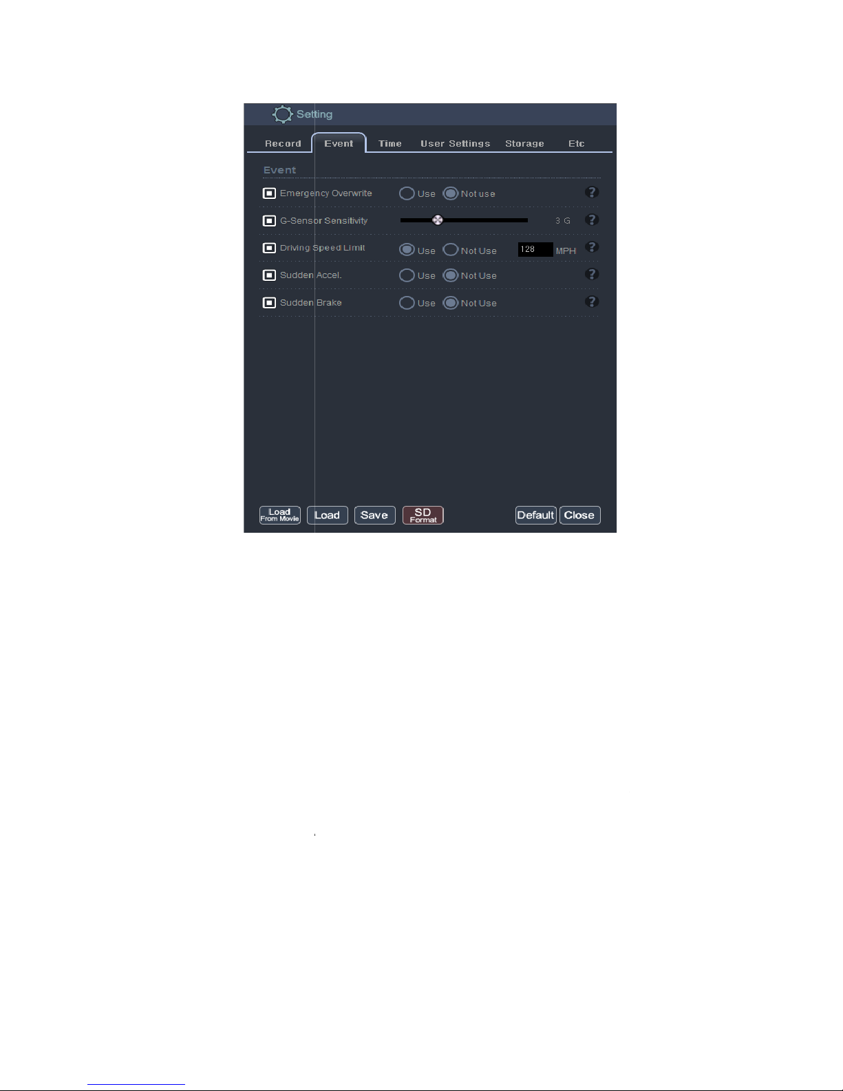
Disables overwrite of previously recorded
) when storage capacity is full
Adjust the sensitivity of the G Sensor to detec
Sensor values (i.e. 2.0G) represents incr
Suggested value is minimum 2.0G to minimize false triggers
: Enable / Disable maximum vehicle speed limit
To monitor Sudden Acceleration f
desired value. System calculates variation at 0.5 second interval
Suggested value is minimum 10 miles to avoid excessive false triggers
To monitor Sudden Braking for fleet safety and efficiency. Enter speed based on desired
System calculates variation at 0.5 second intervals.
is minimum 10 miles to avoid excessive false triggers
Emergency Events (Foot Pedal
t vehicle vibration and shock.
Sensor values (i.e. 3.5G)
EVENT trigger. Enter max speed
Enter speed based on
45
8.6.2 Event setting
- Emergency Overwrite:
Event Button
Recommend: NOT USE
- G-Sensor Sensitivity:
- Driving Speed Limit
- Sudden Accel.:
- Sudden Brake:
value.
Suggested value
eased sensitivity than higher G
or fleet safety and efficiency.
s
.
Emergency
Lower G
Page 46
USER GUIDE V1.0.0
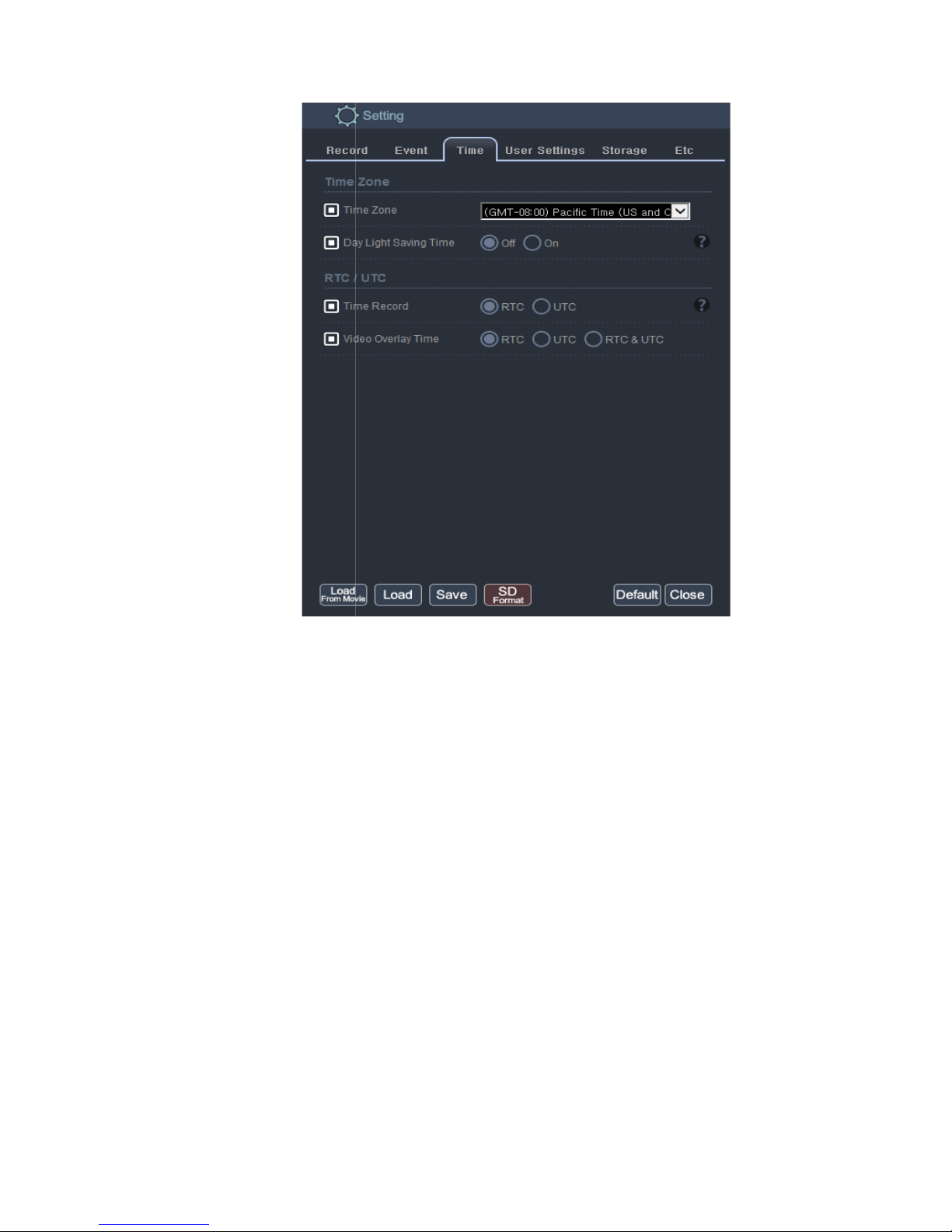
Select the appropriate time zone of the system location
Enable / Disable Daylight Savings Time
All video and data files are saved in this format.
‘RTC’
/RTC: Regional Time in Current
/UTC: Coordinated Universal Time)
/RTC = UTC + Offset Time
46
8.6.3 Time setting
- Time Zone:
- Day Light Saving Time:
- Time Record:
To use local time, select
.
(GMT)
Page 47
USER GUIDE V1.0.0
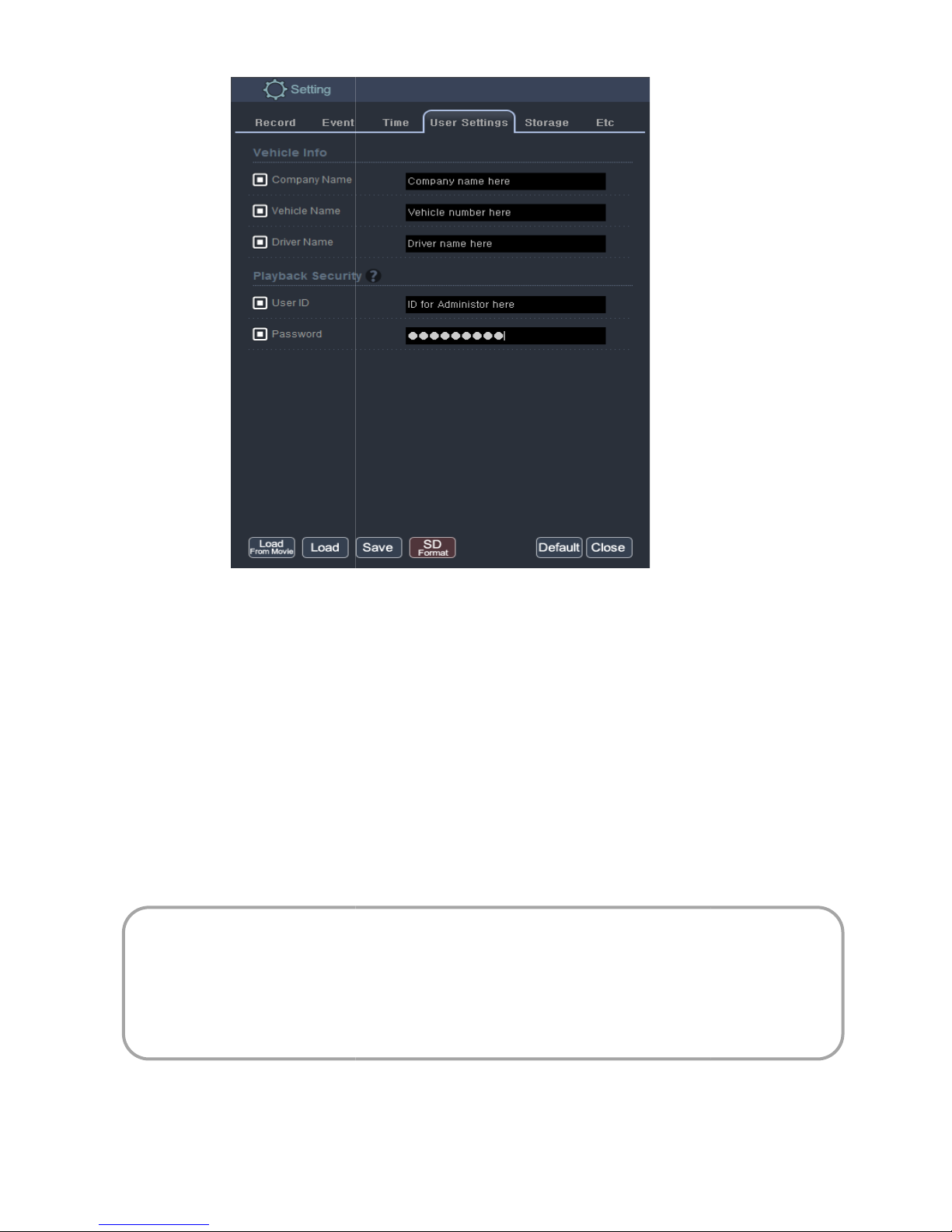
8.6.4 User setting
Enter company name to
company name to embed and display on recorded video
Enter company name to embed and display on recorded video
User name and Password Protection for all files to prevent unauthorized access
are assigned, login credential will be required to view the recorded
Caution
Please safeguard the password as there is no password retrieval option
not be accessed without a password.
format (delete all data) to start new recording
video file
47
- Company name:
- Vehicle name: Enter
- Driver name:
- Playback Security:
If User ID and passwords
data
and the recorded data can
The SD card would require
:
embed and display on recorded
Page 48
USER GUIDE V1.0.0
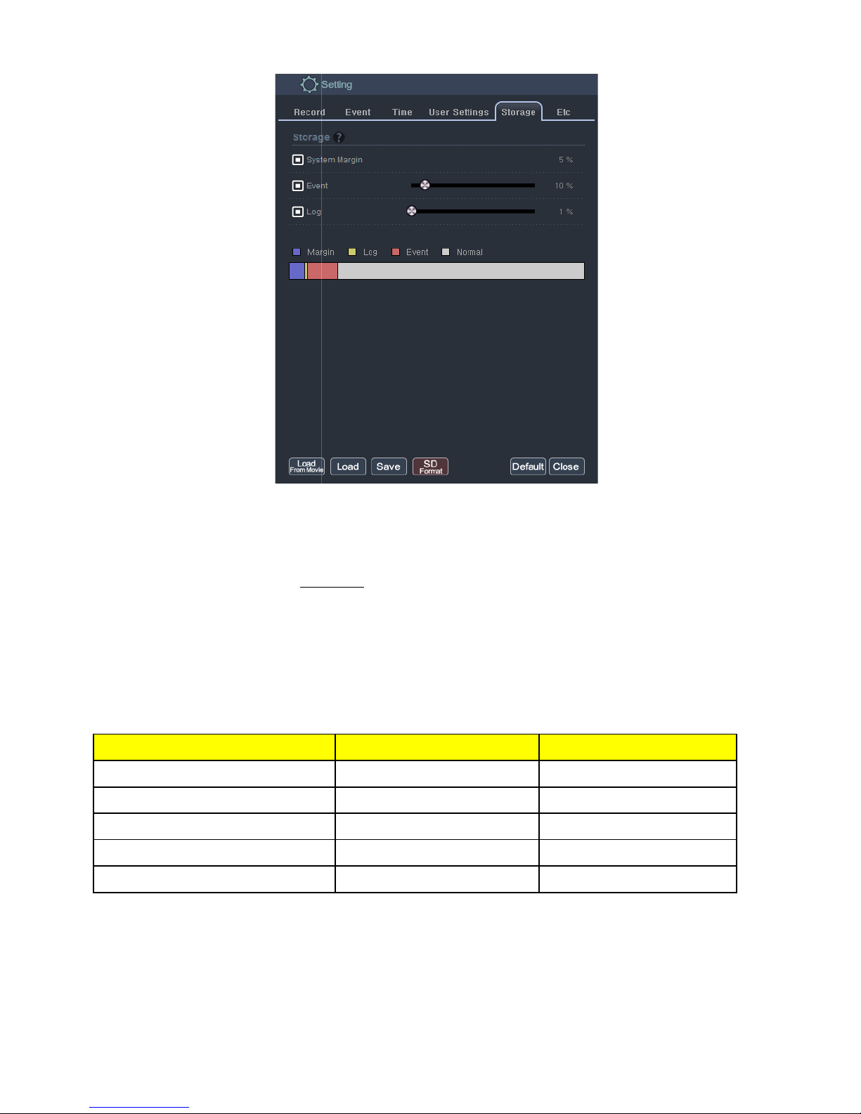
8.6.5 Storage setting
PRIMARY
% storage capacity to
Event = Over Speed, Sudden Acceleration, Sudden Braking
for individual recording
and Impact
Secondary slot
95%
N/A
N/A
N/A
5%
48
Storage setting manages the
segment
*Recommend minimum 30
Storage
micro SD card storage capacity
Event.
, Parking
Primary slot
Normal/Emergency
Event
Park
Log
System Margin
74%
10%
10%
1%
5%
Page 49
USER GUIDE V1.0.0
Watermark, Video Out and LED light indicator
Voice prompt f
*Recommend turning On
Watermark Vehicle, D
When optional LCD monitor is connec
, power down and if SD card
info on video
ted for real time video viewing
switch to rear upon reverse
49
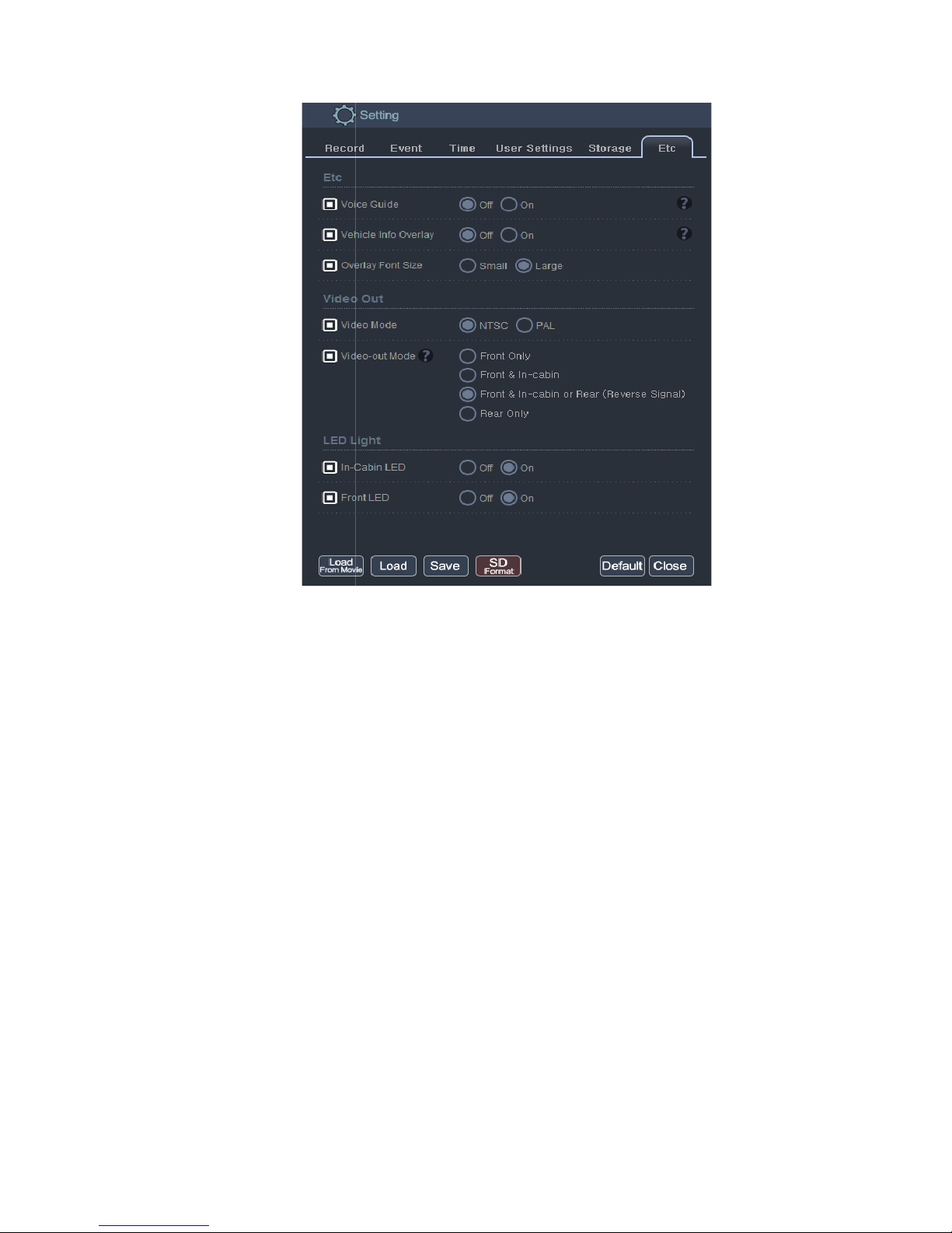
8.6.6 Etc. (Voice Guidance,
- Voice Guide:
is not inserted
- Vehicle Info Overlay:
- Video-out Mode:
back up camera
Front Only:
Front & In-cabin:
Front & In-cabin or Rear:
Rear only:
- LED Light:
In-cabin LED:
Front LED:
or system startup and recording
river and Company
Road facing camera
Both cameras
Front and in-cabin during drive –
Only when reversing the vehicle
Enabling LED for in-cabin recording
LED on to indicate system/recording
)
recordings
/
Page 50
50
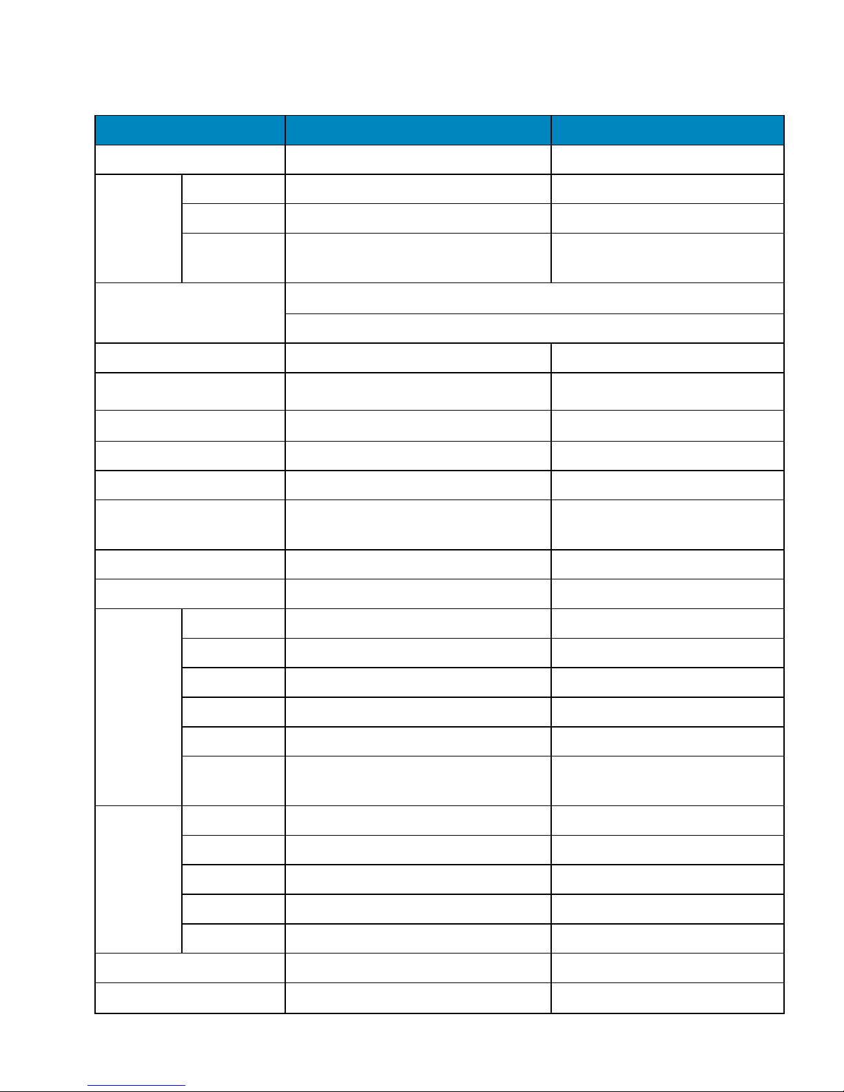
9. Specifications
Component Description Remarks
CPU Coretex-A8 (800MHz) processor Linux ARM
1st/Front HD Digital CMOS Sensor 1280 x 720p (HD)
Camera
2nd/In-cabin HD Digital CMOS Sensor 1280 x 720p (HD)
3rd/Rear
camera
NTSC Analog D1 composite (D1 720 x 480p), Optional
Front: 114.39(H), 61.98(V), 120.0(D)
Camera Angle Lens
In-Cabin: 114.39(H), 61.98(V), 150.0(D)
DDRII RAM 256 MB Samsung
NAND Flash Memory 128 MB Samsung
G-Force sensor 3-Axial acceleration sensor
up to ±8G
Speaker / MIC Mono Speaker / Internal MIC
Super capacitor DC 5V / over 5F Ensures safe shutdown
GPS Module Antenna Built in Cradle
Supports additional external GPS
Antenna
Removable storage micro SDHC(MLC) x 2 slots 64GB max per slot
Video out put NTSC/PAL 3.5mm jack to RCA
GPS signal 2.5Ø 4PIN ear phone jack
USB USB Type-A USB2.0
Rear camera 2.5Ø 4PIN ear phone jack Vehicle reverse gear signal
Hardware
interface
micro USB Micro-USB Type B USB2.0
DC Input 3.5Ø DC input jack
AV-Out 2.5Ø 4PIN ear phone jack
Y-cable when used with EX7-EFP
emergency foot pedal s/w
Format Proprietary Encryption / H.264
Mode 2 Channel 3 Channel
Video
Codec
Front 4Mbps / @30fps 4Mbps/ @27fps
InCabin 2Mbps/ @30fps 2Mbps/Max.@15fps
Rear N/A 512kps/Max.@15fps
Audio Codec PCM Monaural, 22.05Khz, 16bits
Recording Continuous recording
One file / min(60s±1s)
USER GUIDE V1.0.0
Page 51

51
Button Event recording)
SOS Event recording)
G-sensor Event recording)
15 sec.±0.25s before;
15 sec.±0.25s after;
(total 30 sec. event file)
Infrared 4 IR_LEDs (in-cabin camera)
Operating power voltage DC 8V ~ 32V
Operating temperature
Storage temperature
-20℃ to +85℃
-30℃ to +95℃
109(w) x 82(H) x 19(D)
Dimension (mm)
121.9(W) x 104.2(H) x 46.1(D)
Weight Main device: 138g / GPS Cradle : 42g
Warranty Period 1 Year
MTBF 7 years
IR_LEDs switch on and off
automatically when needed
Main body, excluding camera
lens protrusion
Main body with GPS cradle and
tamperproof case, excluding
camera lens protrusion
UL Standard UL94-V0
Certificate RoHs, CE, FCC
※ As an ongoing effort to continuously enhance Ventra products, technical specifications and design
may be changed without prior notice.
RoHS COMPLIANT
Our product complies with “The Restriction of the use of certain Hazardous Substances in electrical and electronic
equipment”, and we do not use the 6 hazardous materials- Cadmium (Cd), Lead (Pb), Mercury (Hg), Hexavalent
Chromium (Cr +6), Poly Brominated Biphenyls (PBBs), Poly Brominated Diphenyl Ethers (PBDEs)- in our products.
USER GUIDE V1.0.0
Page 52

52
10. Warranty
VENTRA LIMITED WARRANTY
Ventra Technology warrants the system against defects in material and workmanship for a period of one
(1) year from the date of original purchase. During this period, Ventra’s liability for any defective product,
or any product part, shall be limited to the repair or replacement of the product, at Ventra’s sole
discretion.
This warranty does not apply to defects or damages resulting from mishandling, accident, abuse,
negligence, lightning, water/liquid, power surges, improper interfacing, operation outside of design limits,
misapplication, improper repair, or unauthorized modification.
The term "Ventra Product" is limited to the hardware components and required firmware. It DOES NOT
include software applications or programs, non-Ventra products or peripherals. To the extent permitted
by local law, all non-Ventra products or non-Ventra branded peripherals - such as external storage SD card
are provided provide
the respective manufacturer's own warranties directly to you, and are not covered by this Limited
Warranty.
To obtain service within the warranty period, please contact Ventra at (888) 418 3833 or
[email protected] for assistance. If product repair or replacement is necessary, a Return Merchandise
Authorization (RMA) will be issued. The Customer will be solely responsible for shipping charges,
insurance and proper packaging to prevent breakage in transit, whether or not the product is covered by
this warranty. All shipments of repaired or replaced products by Ventra will be F.O.B. California.
VENTRA MAKES NO OTHER WARRANTIES, EXPRESS OR IMPLIED, AS TO MERCHANTABILITY OR FITNESS
FOR A PARTICULAR PURPOSE OF ANY PRODUCT SOLD UNDER THIS CONTRACT. UNDER NO
CIRCUMSTANCES SHALL VENTRA BE LIABLE FOR ANY INDIRECT, INCIDENTAL, SPECIAL, PUNITIVE OR
CONSEQUENTIAL DAMAGES INCLUDING, WITHOUT LIMITATION, INFRINGEMENT OF THIRD PARTY
RIGHTS, LOST GOODWILL, LOST REVENUES OR PROFITS, WORK STOPPAGE, DATA LOSS, SYSTEM FAILURE,
IMPAIRMENT OF OTHER GOODS, COSTS OF REMOVAL AND REINSTALLATION OF THE SYSTEM, LOSS OF
USE, INJURY TO PERSONS OR PROPERTY ARISING OUT OR RELATED TO THE SYSTEM WHETHER BASED
ON BREACH OF WARRANTY, BREACH OF CONTRACT, TORT OR OTHERWISE. IN NO EVENT SHALL
VENTRA’s LIABILITY EXCEED THE ACTUAL PURCHASE PRICE OF THE SYSTEM WITH RESPECT TO WHICH
ANY CLAIM IS MADE.
The information in this specification sheet reflects the current technical specifications at the time of
print. Ventra reserve the right to change the technical or physical specifications and features without
prior notification.
While every effort has been made to ensure the accuracy of the information, certain specifications are
based on approximate figures
All trademarks, service marks, trade names, product names and logos are the property of their respective
owners.
USER GUIDE V1.0.0
 Loading...